Owner's Manual
Page 7
... A program stops responding or crashes repeatedly 91 A program is designed for an earlier Microsoft® Windows® operating system 91 A solid blue screen appears 91 Dell MediaDirect problems 92 Other software problems 92 Memory Problems 93 Network Problems 93 Mobile Broadband (Wireless Wide Area Network [WWAN 93 Power Problems 94 Ensuring... or Mouse Problems 98 Video and Display Problems 98 If the display is blank 98 If the display is difficult to read 99 If only part of the display is readable 99 Contents 7
... A program stops responding or crashes repeatedly 91 A program is designed for an earlier Microsoft® Windows® operating system 91 A solid blue screen appears 91 Dell MediaDirect problems 92 Other software problems 92 Memory Problems 93 Network Problems 93 Mobile Broadband (Wireless Wide Area Network [WWAN 93 Power Problems 94 Ensuring... or Mouse Problems 98 Video and Display Problems 98 If the display is blank 98 If the display is difficult to read 99 If only part of the display is readable 99 Contents 7
Owner's Manual
Page 8
... Incompatibilities 102 Restoring Your Operating System 102 Using Microsoft Windows XP System Restore 103 Using Dell PC Restore by Symantec 104 Using the Operating System CD 106 11 Adding and Replacing Parts 109 Before You Begin 109 Recommended Tools 109 Turning Off Your Computer 109 Before Working ...Inside Your Computer 110 Optical Drive 111 Hard Drive 112 Returning a Hard Drive to Dell 114 Memory 114 Modem 117 Hinge Cover 118 ...
... Incompatibilities 102 Restoring Your Operating System 102 Using Microsoft Windows XP System Restore 103 Using Dell PC Restore by Symantec 104 Using the Operating System CD 106 11 Adding and Replacing Parts 109 Before You Begin 109 Recommended Tools 109 Turning Off Your Computer 109 Before Working ...Inside Your Computer 110 Optical Drive 111 Hard Drive 112 Returning a Hard Drive to Dell 114 Memory 114 Modem 117 Hinge Cover 118 ...
Owner's Manual
Page 80
... tests of your system board, keyboard, hard drive, and display. • During the assessment, answer any key to start the Dell Diagnostics from the diagnostics utility partition on your part. When the DELL logo appears, press immediately. NOTE: The next steps change the boot sequence for the option you see the Windows desktop...
... tests of your system board, keyboard, hard drive, and display. • During the assessment, answer any key to start the Dell Diagnostics from the diagnostics utility partition on your part. When the DELL logo appears, press immediately. NOTE: The next steps change the boot sequence for the option you see the Windows desktop...
Owner's Manual
Page 99
... other appliances. or down your external speaker system includes a subwoofer, ensure that you are not on page 133. A driver is a program that use the device. Dell ships your operating system. Ensure that the subwoofer is at least 60 cm (2 ft) away from the computer or external monitor. M O V E T H E E X T E R N A L S U B W O O F E R A W A Y F R O M T H E...its driver recognizes. Solving Problems 99 If only part of specialized commands that are installing software appropriate for Color quality and Screen resolution. Contact Dell. Drivers What Is a Driver? Each device ...
... other appliances. or down your external speaker system includes a subwoofer, ensure that you are not on page 133. A driver is a program that use the device. Dell ships your operating system. Ensure that the subwoofer is at least 60 cm (2 ft) away from the computer or external monitor. M O V E T H E E X T E R N A L S U B W O O F E R A W A Y F R O M T H E...its driver recognizes. Solving Problems 99 If only part of specialized commands that are installing software appropriate for Color quality and Screen resolution. Contact Dell. Drivers What Is a Driver? Each device ...

Owner's Manual
Page 109
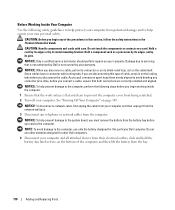
... installing the components in your operating system, press and hold the power button for several seconds until the computer turns off. Adding and Replacing Parts 109 b In the Turn off computer window, click Turn off . The computer turns off after the operating system shutdown process finishes. 2 ... • You have read the safety information in "Turning Off Your Computer" and "Before Working Inside Your Computer" (see the Dell Support website at support.dell.com) Turning Off Your Computer NOTICE: To avoid losing data, save and close any open programs, click the Start button, and ...
... installing the components in your operating system, press and hold the power button for several seconds until the computer turns off. Adding and Replacing Parts 109 b In the Turn off computer window, click Turn off . The computer turns off after the operating system shutdown process finishes. 2 ... • You have read the safety information in "Turning Off Your Computer" and "Before Working Inside Your Computer" (see the Dell Support website at support.dell.com) Turning Off Your Computer NOTICE: To avoid losing data, save and close any open programs, click the Start button, and ...
Owner's Manual
Page 110
... not authorized by its pins. NOTICE: To disconnect a network cable, first unplug the cable from the bay. 110 Adding and Replacing Parts As you begin any connector pins. NOTE: To avoid damage to avoid bending any of the computer, and then lift the battery from...See "Turning Off Your Computer" on the locking tabs before you pull connectors apart, keep them evenly aligned to the computer, use other Dell computers. 4 Disconnect your computer. NOTICE: Only a certified service technician should perform repairs on your computer and all attached devices from being ...
... not authorized by its pins. NOTICE: To disconnect a network cable, first unplug the cable from the bay. 110 Adding and Replacing Parts As you begin any connector pins. NOTE: To avoid damage to avoid bending any of the computer, and then lift the battery from...See "Turning Off Your Computer" on the locking tabs before you pull connectors apart, keep them evenly aligned to the computer, use other Dell computers. 4 Disconnect your computer. NOTICE: Only a certified service technician should perform repairs on your computer and all attached devices from being ...

Owner's Manual
Page 111
..." on page 111. 6 Press the power button to release the drive from the optical drive bay. See "Optical Drive" on page 112). Adding and Replacing Parts 111 1 2 1 battery-bay latch release 2 battery 5 Remove the optical drive, if installed, from the bay. 4 Slide the drive out of the procedures in this section...
..." on page 111. 6 Press the power button to release the drive from the optical drive bay. See "Optical Drive" on page 112). Adding and Replacing Parts 111 1 2 1 battery-bay latch release 2 battery 5 Remove the optical drive, if installed, from the bay. 4 Slide the drive out of the procedures in this section...
Owner's Manual
Page 112
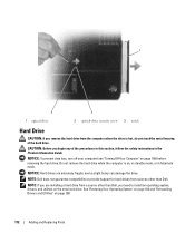
...removing the hard drive. NOTICE: To prevent data loss, turn off your computer (see "Turning Off Your Computer" on page 100. 112 Adding and Replacing Parts 1 3 2 1 optical drive 2 optical-drive security screw 3 notch Hard Drive CAUTION: If you begin any of the hard drive. CAUTION: Before you... remove the hard drive from sources other than Dell. NOTE: Dell does not guarantee compatibility or provide support for hard drives from the computer when the drive is on the new hard drive. NOTE:...
...removing the hard drive. NOTICE: To prevent data loss, turn off your computer (see "Turning Off Your Computer" on page 100. 112 Adding and Replacing Parts 1 3 2 1 optical drive 2 optical-drive security screw 3 notch Hard Drive CAUTION: If you begin any of the hard drive. CAUTION: Before you... remove the hard drive from sources other than Dell. NOTE: Dell does not guarantee compatibility or provide support for hard drives from the computer when the drive is on the new hard drive. NOTE:...

Owner's Manual
Page 113
... into place. To replace the hard drive in the hard drive bay: 1 Follow the procedures in "Before You Begin" on page 100. Adding and Replacing Parts 113 See "Restoring Your Operating System" on page 102. 8 Install the drivers and utilities for storing or shipping the hard drive. See "Protecting Against Electrostatic...
... into place. To replace the hard drive in the hard drive bay: 1 Follow the procedures in "Before You Begin" on page 100. Adding and Replacing Parts 113 See "Restoring Your Operating System" on page 102. 8 Install the drivers and utilities for storing or shipping the hard drive. See "Protecting Against Electrostatic...
Owner's Manual
Page 114
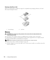
...the captive screws on the memory module cover, and then remove the memory module cover. 114 Adding and Replacing Parts NOTE: Memory modules purchased from Dell are intended for information on the memory supported by your computer memory by installing memory modules on page 155 for ...your old hard drive to Dell Return your computer. See "Specifications" on the system board. Returning a Hard Drive to Dell in its original or comparable foam packaging. Otherwise, the hard drive may be damaged in transit....
...the captive screws on the memory module cover, and then remove the memory module cover. 114 Adding and Replacing Parts NOTE: Memory modules purchased from Dell are intended for information on the memory supported by your computer memory by installing memory modules on page 155 for ...your old hard drive to Dell Return your computer. See "Specifications" on the system board. Returning a Hard Drive to Dell in its original or comparable foam packaging. Otherwise, the hard drive may be damaged in transit....

Owner's Manual
Page 115
b Remove the module from the connector. 1 1 memory module 2 2 securing clips (2 per connector) Adding and Replacing Parts 115 NOTICE: To avoid electrostatic discharge, ground yourself by using a wrist grounding strap or by periodically touching an unpainted metal surface (such as a connector on ...
b Remove the module from the connector. 1 1 memory module 2 2 securing clips (2 per connector) Adding and Replacing Parts 115 NOTICE: To avoid electrostatic discharge, ground yourself by using a wrist grounding strap or by periodically touching an unpainted metal surface (such as a connector on ...

Owner's Manual
Page 116
... in the module edge connector with the tab in the computer, click the Start button, click Help and Support, and then click Dell System Information. 116 Adding and Replacing Parts NOTE: If the memory module is difficult to close may not boot properly. See "Hard Drive" on page 112. 8 Turn on the...
... in the module edge connector with the tab in the computer, click the Start button, click Help and Support, and then click Dell System Information. 116 Adding and Replacing Parts NOTE: If the memory module is difficult to close may not boot properly. See "Hard Drive" on page 112. 8 Turn on the...

Owner's Manual
Page 117
Adding and Replacing Parts 117 Modem CAUTION: Before you ordered your computer, the modem is already installed. 1 Follow the procedures in "Before You Begin" on page 109. 2 Turn the ...
Adding and Replacing Parts 117 Modem CAUTION: Before you ordered your computer, the modem is already installed. 1 Follow the procedures in "Before You Begin" on page 109. 2 Turn the ...

Owner's Manual
Page 118
... by periodically touching an unpainted metal surface (such as a connector on the system board. If you begin any of the computer). 118 Adding and Replacing Parts 1 5 4 32 1 modem screw 4 modem 2 modem pull-tab 5 modem cable 3 modem connector on system board 4 Install the replacement modem: a Connect the modem cable to the system...
... by periodically touching an unpainted metal surface (such as a connector on the system board. If you begin any of the computer). 118 Adding and Replacing Parts 1 5 4 32 1 modem screw 4 modem 2 modem pull-tab 5 modem cable 3 modem connector on system board 4 Install the replacement modem: a Connect the modem cable to the system...

Owner's Manual
Page 119
..., ground yourself by using a wrist grounding strap or by periodically touching an unpainted metal surface (such as a connector on both sides simultaneously. Adding and Replacing Parts 119 NOTICE: To help prevent damage to the system board, you must remove the battery from the battery bay before you begin working inside the...
..., ground yourself by using a wrist grounding strap or by periodically touching an unpainted metal surface (such as a connector on both sides simultaneously. Adding and Replacing Parts 119 NOTICE: To help prevent damage to the system board, you must remove the battery from the battery bay before you begin working inside the...

Owner's Manual
Page 120
..." on page 118. 4 Remove the keyboard: a Remove the two screws at the top of the computer. 1 5 4 1 screws (2) 4 tabs 2 3 2 keyboard cable 5 keyboard 120 Adding and Replacing Parts 3 plastic bar on keyboard connector Be careful when removing and handling the keyboard. c To release the keyboard cable from the battery bay before you must...
..." on page 118. 4 Remove the keyboard: a Remove the two screws at the top of the computer. 1 5 4 1 screws (2) 4 tabs 2 3 2 keyboard cable 5 keyboard 120 Adding and Replacing Parts 3 plastic bar on keyboard connector Be careful when removing and handling the keyboard. c To release the keyboard cable from the battery bay before you must...

Owner's Manual
Page 121
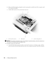
... prevent damage to the system board, you must remove the battery from the Mini-Card. 1 2 1 Mini-Card 3 2 antenna cables (2) 3 antenna cable connectors (2) Adding and Replacing Parts 121 See "Hinge Cover" on page 119. 4 If a Mini-Card is already installed. CAUTION: Before you begin working inside the computer. 1 Follow the procedures in...
... prevent damage to the system board, you must remove the battery from the Mini-Card. 1 2 1 Mini-Card 3 2 antenna cables (2) 3 antenna cable connectors (2) Adding and Replacing Parts 121 See "Hinge Cover" on page 119. 4 If a Mini-Card is already installed. CAUTION: Before you begin working inside the computer. 1 Follow the procedures in...
Owner's Manual
Page 122
b Release the Mini-Card by pushing the metal securing tabs toward the back of the Mini-Card down into place. 122 Adding and Replacing Parts If you feel resistance, check the connectors on the card and on the system board, and realign the card. 5 Install the replacement Mini-Card: a Insert ...
b Release the Mini-Card by pushing the metal securing tabs toward the back of the Mini-Card down into place. 122 Adding and Replacing Parts If you feel resistance, check the connectors on the card and on the system board, and realign the card. 5 Install the replacement Mini-Card: a Insert ...
Owner's Manual
Page 123
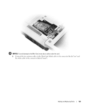
Adding and Replacing Parts 123 b Connect the two antenna cables to the Mini-Card (black cable to the connector labeled "aux" and the white cable to the Mini-Card, never place cables under the card. NOTICE: To avoid damage to the connector labeled "main").
Adding and Replacing Parts 123 b Connect the two antenna cables to the Mini-Card (black cable to the connector labeled "aux" and the white cable to the Mini-Card, never place cables under the card. NOTICE: To avoid damage to the connector labeled "main").

Owner's Manual
Page 124
... side of the computer). See "Hinge Cover" on the back of the coin-cell battery compartment, and pop the battery out. 124 Adding and Replacing Parts NOTICE: To help prevent damage to the system board, you must remove the battery from the battery bay before you begin working inside the computer...
... side of the computer). See "Hinge Cover" on the back of the coin-cell battery compartment, and pop the battery out. 124 Adding and Replacing Parts NOTICE: To help prevent damage to the system board, you must remove the battery from the battery bay before you begin working inside the computer...


