
HP DesignJet 1000 Series Take-Up Reel UserÂ’s Guide - C6079-90001
Page 33
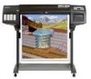
NOTE: You can use an empty cardboard tube to replace the plastic take -up core is pushed firmly into both paper guides. 33 HP DesignJet 1000 Series Take-Up Reel NOTE: Ensure the take -up core. 5 Install the new core you are using. By matching color coded lengths of standard paper sizes: 24", 36". 12... you have chosen onto the spindle and re-install the left -hand paper guide. 4 Remove the old take -up core for different widths of plastic tube, you can make a take-up core that was supplied with your printer. 3 Remove the left hand guide assembly.
NOTE: You can use an empty cardboard tube to replace the plastic take -up core is pushed firmly into both paper guides. 33 HP DesignJet 1000 Series Take-Up Reel NOTE: Ensure the take -up core. 5 Install the new core you are using. By matching color coded lengths of standard paper sizes: 24", 36". 12... you have chosen onto the spindle and re-install the left -hand paper guide. 4 Remove the old take -up core for different widths of plastic tube, you can make a take-up core that was supplied with your printer. 3 Remove the left hand guide assembly.

Service Manual
Page 9
... Station Assembly 8-8 Drop Detector Assembly 8-10 Vacuum Fan 8-11 Paper-axis Motor Assembly 8-12 Left Hand Cover 8-13 Left Hand Trim Assembly 8-18 Ink Supply Station Assembly (ISS) 8-19 Air Pressurization System (APS) 8-20 Clutch Assembly and left hand miscellaneous parts 8-21 Tail Deflectors and Rear Platen 8-23 Left and Right Rear Covers 8-24 HP DesignJets 1050C and 1055CM Printers...
... Station Assembly 8-8 Drop Detector Assembly 8-10 Vacuum Fan 8-11 Paper-axis Motor Assembly 8-12 Left Hand Cover 8-13 Left Hand Trim Assembly 8-18 Ink Supply Station Assembly (ISS) 8-19 Air Pressurization System (APS) 8-20 Clutch Assembly and left hand miscellaneous parts 8-21 Tail Deflectors and Rear Platen 8-23 Left and Right Rear Covers 8-24 HP DesignJets 1050C and 1055CM Printers...

Service Manual
Page 10
... Platen Assembly 8-62 Platen Assembly 8-63 Paper Entry Assembly 8-64 Roller Guide 8-66 Media Holder Strip 8-69 Drive Roller 8-70 Center Guide 8-71 Pinch-Wheel Assembly and Cam 8-73 Preventive Maintenance 9-1 Moisture on the Printer 9-2 Noisy Carriage Bushing 9-2 Belt Swelling 9-2 Cleaning the Printer 9-2 General Cleaning 9-2 Cleaning the Overdrive 9-3 Scheduled Maintenance 9-3 Level of Printer Usage 9-3 Scan-axis Maintenance 9-4 8 HP DesignJets 1050C...
... Platen Assembly 8-62 Platen Assembly 8-63 Paper Entry Assembly 8-64 Roller Guide 8-66 Media Holder Strip 8-69 Drive Roller 8-70 Center Guide 8-71 Pinch-Wheel Assembly and Cam 8-73 Preventive Maintenance 9-1 Moisture on the Printer 9-2 Noisy Carriage Bushing 9-2 Belt Swelling 9-2 Cleaning the Printer 9-2 General Cleaning 9-2 Cleaning the Overdrive 9-3 Scheduled Maintenance 9-3 Level of Printer Usage 9-3 Scan-axis Maintenance 9-4 8 HP DesignJets 1050C...

Service Manual
Page 50
...Calibrations Backup ⇒ Page 5-19. Using this procedure you select "Tubes Replaced" when performing the Calibrations Backup. n Remove the Drop Detector and make sure that you will be able to the Service Station Cable. n Replace the Drop Detector Assembly ⇒ Page 8-10. n Check that the Drop Detector Cable ... if the error has gone before replacing another component. NOTE Make sure that there are no obstacles inside which component failed. 2-16 HP DesignJets 1050C and 1055CM Printers Service Manual System Error: 0C0030 Problem Description: Bad Drop Detector.
...Calibrations Backup ⇒ Page 5-19. Using this procedure you select "Tubes Replaced" when performing the Calibrations Backup. n Remove the Drop Detector and make sure that you will be able to the Service Station Cable. n Replace the Drop Detector Assembly ⇒ Page 8-10. n Check that the Drop Detector Cable ... if the error has gone before replacing another component. NOTE Make sure that there are no obstacles inside which component failed. 2-16 HP DesignJets 1050C and 1055CM Printers Service Manual System Error: 0C0030 Problem Description: Bad Drop Detector.

Service Manual
Page 91
...INSIDE. Service Tests 1. You must perform the Scan-Axis Test after: n Scan-Axis Assemblies are disassembled or replaced. ALL THE COVER SENSORS ARE DISABLED WHEN IN THE SERVICE TESTS MENU....in order to get values that once you have finished with the Printheads and the Tubes System installed in a special Mode which does NOT require the full Initialization of the...the Printer and Power ON again before trying to verify the operation of the Printer. Ink Pressure System 5. Scan Axis Top Back ↑ Make Selection ↓ Enter Press Enter HP DesignJets 1050C and 1055CM Printers ...
...INSIDE. Service Tests 1. You must perform the Scan-Axis Test after: n Scan-Axis Assemblies are disassembled or replaced. ALL THE COVER SENSORS ARE DISABLED WHEN IN THE SERVICE TESTS MENU....in order to get values that once you have finished with the Printheads and the Tubes System installed in a special Mode which does NOT require the full Initialization of the...the Printer and Power ON again before trying to verify the operation of the Printer. Ink Pressure System 5. Scan Axis Top Back ↑ Make Selection ↓ Enter Press Enter HP DesignJets 1050C and 1055CM Printers ...

Service Manual
Page 118
...Paper-Axis is disassembled Yes No No No No Yes No No No or replaced Platen Assembly is disassembled or replaced No No Yes No No Yes No No Yes Service Station ...No Drive Roller is disassembled or replaced Yes No No No No Yes No No No Tubes System (SRK) is disassembled or replaced No No No No No No Yes Yes No...Color Accuracy Problem No No No No No No No No No Edge Detect Problems No Yes No No No No No No No NOTE Refer to determine when calibrations are required. Refer to the table below to the following page for the relevant Calibration. 5-2 HP DesignJets 1050C and 1055CM Printers...
...Paper-Axis is disassembled Yes No No No No Yes No No No or replaced Platen Assembly is disassembled or replaced No No Yes No No Yes No No Yes Service Station ...No Drive Roller is disassembled or replaced Yes No No No No Yes No No No Tubes System (SRK) is disassembled or replaced No No No No No No Yes Yes No...Color Accuracy Problem No No No No No No No No No Edge Detect Problems No Yes No No No No No No No NOTE Refer to determine when calibrations are required. Refer to the table below to the following page for the relevant Calibration. 5-2 HP DesignJets 1050C and 1055CM Printers...
Service Manual
Page 119
...that are given on the Drive Roller. 5 Pen to Paper Spacing ⇒ Page 5-15 THIS CALIBRATION IS NO LONGER REQUIRED. 6 Color to Color Calibration ⇒ Page 5-16 The purpose of this Service Calibration is to correct the alignment between the Carriage and the Center Platen. ...the Electronics Module or the Tubes System is replaced. 8 Pen Alignment ⇒ Page 5-22 The purpose of this Service Calibration is to calibrate the nominal advance of the media in order to control the exact movement of the media. HP DesignJets 1050C and 1055CM Printers Service Manual 5-3 This calibration...
...that are given on the Drive Roller. 5 Pen to Paper Spacing ⇒ Page 5-15 THIS CALIBRATION IS NO LONGER REQUIRED. 6 Color to Color Calibration ⇒ Page 5-16 The purpose of this Service Calibration is to correct the alignment between the Carriage and the Center Platen. ...the Electronics Module or the Tubes System is replaced. 8 Pen Alignment ⇒ Page 5-22 The purpose of this Service Calibration is to calibrate the nominal advance of the media in order to control the exact movement of the media. HP DesignJets 1050C and 1055CM Printers Service Manual 5-3 This calibration...

Service Manual
Page 173
Parts and Diagrams 77 Printer Support 7-2 Rear Covers 7-4 Electronics Module 7-6 Right Hand Cover 7-8 Left Hand Cover and Window 7-10 Right Hand Assemblies 7-12 ISS and APS Assembly 7-14 Clutch Assembly 7-16 Carriage Assembly 7-18 Scan-Axis Assemblies 7-20 Drive Roller and ARSS Miscellaneous Parts 7-22 Paper Path Assemblies 7-24 Pinch Assembly 7-26 Drive Roller Assemblies 7-28 Center Guide and Media Sensor 7-30 Tubes Guide Assemblies 7-32 Ordering Accessories 7-34 HP DesignJets 1050C and 1055CM Printers Service Manual 7-1
Parts and Diagrams 77 Printer Support 7-2 Rear Covers 7-4 Electronics Module 7-6 Right Hand Cover 7-8 Left Hand Cover and Window 7-10 Right Hand Assemblies 7-12 ISS and APS Assembly 7-14 Clutch Assembly 7-16 Carriage Assembly 7-18 Scan-Axis Assemblies 7-20 Drive Roller and ARSS Miscellaneous Parts 7-22 Paper Path Assemblies 7-24 Pinch Assembly 7-26 Drive Roller Assemblies 7-28 Center Guide and Media Sensor 7-30 Tubes Guide Assemblies 7-32 Ordering Accessories 7-34 HP DesignJets 1050C and 1055CM Printers Service Manual 7-1

Service Manual
Page 204
Parts and Diagrams Tubes Guide Assemblies Reference on Drawing 1 2 3 4 5 Printer Support HP Part Number Quantity Description/Comments C6072-60195 C6072-60194 C6072-60193 0624-0771 C6072-60192 1 Tube Guide Assembly 1 Front Guide Assembly 1 Right Arc Assembly 8 Screw 1 Left Arc Assembly 7-32 HP DesignJets 1050C and 1055CM Printers Service Manual
Parts and Diagrams Tubes Guide Assemblies Reference on Drawing 1 2 3 4 5 Printer Support HP Part Number Quantity Description/Comments C6072-60195 C6072-60194 C6072-60193 0624-0771 C6072-60192 1 Tube Guide Assembly 1 Front Guide Assembly 1 Right Arc Assembly 8 Screw 1 Left Arc Assembly 7-32 HP DesignJets 1050C and 1055CM Printers Service Manual

Service Manual
Page 205
4 Right Hand Side 3 5 4 Left Hand Side Parts and Diagrams 4 4 1 2 4 Figure 18: SRK Tubes Guide Assemblies HP DesignJets 1050C and 1055CM Printers Service Manual 7-33
4 Right Hand Side 3 5 4 Left Hand Side Parts and Diagrams 4 4 1 2 4 Figure 18: SRK Tubes Guide Assemblies HP DesignJets 1050C and 1055CM Printers Service Manual 7-33
Service Manual
Page 209
... Motor Assembly 8-33 Encoder Strip 8-34 Tensioner 8-37 Trailing Cable 8-39 Cutter Assembly 8-42 Carriage Assembly and Belt 8-44 Tubes System Assembly 8-53 Ink Leak Detector Assembly 8-60 Front Platen Assembly 8-62 Platen Assembly 8-63 Paper Entry Assembly 8-64 Roller Guide 8-66 Media Holder Strip 8-69 Drive Roller 8-70 Center Guide 8-71 Pinch-Wheel Assembly and Cam 8-73 HP DesignJets 1050C and 1055CM Printers...
... Motor Assembly 8-33 Encoder Strip 8-34 Tensioner 8-37 Trailing Cable 8-39 Cutter Assembly 8-42 Carriage Assembly and Belt 8-44 Tubes System Assembly 8-53 Ink Leak Detector Assembly 8-60 Front Platen Assembly 8-62 Platen Assembly 8-63 Paper Entry Assembly 8-64 Roller Guide 8-66 Media Holder Strip 8-69 Drive Roller 8-70 Center Guide 8-71 Pinch-Wheel Assembly and Cam 8-73 HP DesignJets 1050C and 1055CM Printers...

Service Manual
Page 222
Release the tube holder (item 1) from the rear of the ink cartridge tube connector outwards (refer to Figure 9). 1 2082a Figure 9: Tube Grip 3. Twist the two latches at the rear of the left hand cover by pushing it up and out (refer to Figure 10). Removal and Installation 2. This will release the complete assembly. 1 8-14 2 Figure 10: Latches HP DesignJets 1050C and 1055CM Printers Service Manual
Release the tube holder (item 1) from the rear of the ink cartridge tube connector outwards (refer to Figure 9). 1 2082a Figure 9: Tube Grip 3. Twist the two latches at the rear of the left hand cover by pushing it up and out (refer to Figure 10). Removal and Installation 2. This will release the complete assembly. 1 8-14 2 Figure 10: Latches HP DesignJets 1050C and 1055CM Printers Service Manual

Service Manual
Page 223
Removal and Installation 4. Slide the ink cartridge tube connector assembly towards you (refer to Figure 12). 1 Figure 12: Ink Cartridge Tube Connector Cable HP DesignJets 1050C and 1055CM Printers Service Manual 8-15 Disconnect the ink cartridge tube connector cable (refer to Figure 11). 1 2082c Figure 11: Ink Cartridge Tube Connector (pulled back) 5.
Removal and Installation 4. Slide the ink cartridge tube connector assembly towards you (refer to Figure 12). 1 Figure 12: Ink Cartridge Tube Connector Cable HP DesignJets 1050C and 1055CM Printers Service Manual 8-15 Disconnect the ink cartridge tube connector cable (refer to Figure 11). 1 2082c Figure 11: Ink Cartridge Tube Connector (pulled back) 5.
Service Manual
Page 228
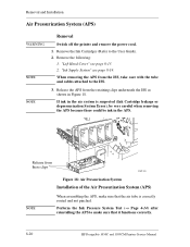
...14) after reinstalling the APS to make sure that it functions correctly. 8-20 HP DesignJets 1050C and 1055CM Printers Service Manual "Left Hand Cover" see page 8-19. Release from the ISS, take care with the tube and cables attached to the User Guide). 2. When removing the APS from these ...clips C607443 Figure 18: Air Pressurization System Installation of the Air Pressurization System (APS) NOTE When assembling the APS, make sure that the air tube is suspected (Ink Cartridge leakage or depressurization System Error), be very careful when removing the APS because there...
...14) after reinstalling the APS to make sure that it functions correctly. 8-20 HP DesignJets 1050C and 1055CM Printers Service Manual "Left Hand Cover" see page 8-19. Release from the ISS, take care with the tube and cables attached to the User Guide). 2. When removing the APS from these ...clips C607443 Figure 18: Air Pressurization System Installation of the Air Pressurization System (APS) NOTE When assembling the APS, make sure that the air tube is suspected (Ink Cartridge leakage or depressurization System Error), be very careful when removing the APS because there...

Service Manual
Page 250
"Top Cover" see page 8-31. 2. Move the carriage to a position where you can access the printhead tube connector (refer to Figure 40. Printhead tube connector Figure 38: Cutter Assembly 8-42 HP DesignJets 1050C and 1055CM Printers Service Manual WARNING Removal Switch off the printer and remove the power cord. 1. Remove the following: 1. Removal and Installation Cutter Assembly Refer to Figure 38 to Figure 38).
"Top Cover" see page 8-31. 2. Move the carriage to a position where you can access the printhead tube connector (refer to Figure 40. Printhead tube connector Figure 38: Cutter Assembly 8-42 HP DesignJets 1050C and 1055CM Printers Service Manual WARNING Removal Switch off the printer and remove the power cord. 1. Remove the following: 1. Removal and Installation Cutter Assembly Refer to Figure 38 to Figure 38).

Service Manual
Page 251
View from the Printer. 4 1 2 3 Figure 40: Cutter Assembly C607417a HP DesignJets 1050C and 1055CM Printers Service Manual 8-43 Push in here Printhead tube connector a. Loosen this screw a. Slide the Cutter Assembly (item 3) towards you and remove from the rear c. Pull here NOTE Figure 39: Cutter Assembly 5. Remove the printhead tube connector (refer to a safe position. Move the Printhead tube connector to Figure...
View from the Printer. 4 1 2 3 Figure 40: Cutter Assembly C607417a HP DesignJets 1050C and 1055CM Printers Service Manual 8-43 Push in here Printhead tube connector a. Loosen this screw a. Slide the Cutter Assembly (item 3) towards you and remove from the rear c. Pull here NOTE Figure 39: Cutter Assembly 5. Remove the printhead tube connector (refer to a safe position. Move the Printhead tube connector to Figure...

Service Manual
Page 252
WARNING Removal Switch off the printer and remove the power cord. 1. "Top Cover" see page 8-4. 3. Move the carriage to a position where you can access the printhead tube connector (refer to Figure 51. "Right Hand Cover" see page 8-31. 2. Removal and Installation Carriage Assembly and Belt Refer to Figure 41 to Figure 41). "Left Hand Cover" see page 8-13. 2. Printhead tube connector Figure 41: Carriage Assembly and Belt 8-44 HP DesignJets 1050C and 1055CM Printers Service Manual Remove the following: 1.
WARNING Removal Switch off the printer and remove the power cord. 1. "Top Cover" see page 8-4. 3. Move the carriage to a position where you can access the printhead tube connector (refer to Figure 51. "Right Hand Cover" see page 8-31. 2. Removal and Installation Carriage Assembly and Belt Refer to Figure 41 to Figure 41). "Left Hand Cover" see page 8-13. 2. Printhead tube connector Figure 41: Carriage Assembly and Belt 8-44 HP DesignJets 1050C and 1055CM Printers Service Manual Remove the following: 1.

Service Manual
Page 253
HP DesignJets 1050C and 1055CM Printers Service Manual 8-45 Loosen this screw a. Push in here Printhead tube connector a. NOTE Removal and Installation For steps 3 and 4, refer to a safe position. Push in here b. View from the rear c. Move the Printhead tube connector to Figure 42. 3. Remove the printhead tube connector (refer to Figure 42). Pull here Figure 42: Carriage Assembly and Belt 5. Loosen the retaining screw T-9 at the back of the printhead tube connector. 4.
HP DesignJets 1050C and 1055CM Printers Service Manual 8-45 Loosen this screw a. Push in here Printhead tube connector a. NOTE Removal and Installation For steps 3 and 4, refer to a safe position. Push in here b. View from the rear c. Move the Printhead tube connector to Figure 42. 3. Remove the printhead tube connector (refer to Figure 42). Pull here Figure 42: Carriage Assembly and Belt 5. Loosen the retaining screw T-9 at the back of the printhead tube connector. 4.
Service Manual
Page 261
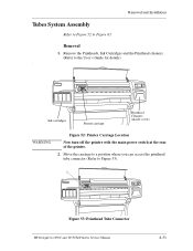
Removal 1. Removal and Installation Tubes System Assembly Refer to Figure 52 to Figure 53). 1 Figure 53: Printhead Tube Connector HP DesignJets 1050C and 1055CM Printers Service Manual 8-53 Move the carriage to a position where you can access the printhead tube connector (Refer to Figure 63. Ink cartridges Printer carriage Printhead Cleaners (inside cover) WARNING Figure 52: Printer Carriage Location Now turn...
Removal 1. Removal and Installation Tubes System Assembly Refer to Figure 52 to Figure 53). 1 Figure 53: Printhead Tube Connector HP DesignJets 1050C and 1055CM Printers Service Manual 8-53 Move the carriage to a position where you can access the printhead tube connector (Refer to Figure 63. Ink cartridges Printer carriage Printhead Cleaners (inside cover) WARNING Figure 52: Printer Carriage Location Now turn...

Service Manual
Page 264
This will release the complete assembly (refer to Figure 59). 1 2082c Figure 59: Ink Cartridge Tube Connector (pulled back) 8-56 HP DesignJets 1050C and 1055CM Printers Service Manual Slide the ink cartridge tube connector assembly (item 1) towards you (refer to Figure 58). 1 2 2082a Figure 58: Latches 10. Removal and Installation 9. Twist the two latches (item 1) at the rear of the ink cartridge tube connector (item 2) to the outwards.
This will release the complete assembly (refer to Figure 59). 1 2082c Figure 59: Ink Cartridge Tube Connector (pulled back) 8-56 HP DesignJets 1050C and 1055CM Printers Service Manual Slide the ink cartridge tube connector assembly (item 1) towards you (refer to Figure 58). 1 2 2082a Figure 58: Latches 10. Removal and Installation 9. Twist the two latches (item 1) at the rear of the ink cartridge tube connector (item 2) to the outwards.


