
Service Manual
Page 10
...Media Sensor 8-29 Window 8-30 Top Cover 8-31 Back Cover 8-32 Scan-axis Motor Assembly 8-33 Encoder Strip 8-34 Tensioner 8-37 Trailing Cable 8-39 Cutter Assembly 8-42 Carriage Assembly and Belt 8-44 Tubes System Assembly 8-53 Ink Leak Detector... Guide 8-71 Pinch-Wheel Assembly and Cam 8-73 Preventive Maintenance 9-1 Moisture on the Printer 9-2 Noisy Carriage Bushing 9-2 Belt Swelling 9-2 Cleaning the Printer 9-2 General Cleaning 9-2 Cleaning the Overdrive 9-3 Scheduled Maintenance 9-3 Level of Printer Usage 9-3 Scan-axis Maintenance 9-4 8 HP DesignJets 1050C and 1055CM Printers Service Manual
...Media Sensor 8-29 Window 8-30 Top Cover 8-31 Back Cover 8-32 Scan-axis Motor Assembly 8-33 Encoder Strip 8-34 Tensioner 8-37 Trailing Cable 8-39 Cutter Assembly 8-42 Carriage Assembly and Belt 8-44 Tubes System Assembly 8-53 Ink Leak Detector... Guide 8-71 Pinch-Wheel Assembly and Cam 8-73 Preventive Maintenance 9-1 Moisture on the Printer 9-2 Noisy Carriage Bushing 9-2 Belt Swelling 9-2 Cleaning the Printer 9-2 General Cleaning 9-2 Cleaning the Overdrive 9-3 Scheduled Maintenance 9-3 Level of Printer Usage 9-3 Scan-axis Maintenance 9-4 8 HP DesignJets 1050C and 1055CM Printers Service Manual
Service Manual
Page 192
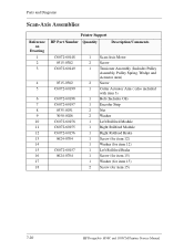
...Drawing 1 2 3 4 5 6 7 8 9 10 11 12 13 14 15 16 17 18 Printer Support HP Part Number Quantity Description/Comments C6072-60148 0515-0382 C6072-60149 0515-0382 C6072-60199 C6072-60198 C6072-60197... 0535-0031 3050-0026 C6072-60158 C6072-60155 C6072-60156 0624-0704 C6072-60157 0624-0704 1 Scan-Axis Motor 2 Screw 1 Tensioner... Left Rollfeed Brake 1 Screw (for item 15) 1 Washer (for item 15) 2 Screw (for item 15) 7-20 HP DesignJets 1050C and 1055CM Printers Service Manual
...Drawing 1 2 3 4 5 6 7 8 9 10 11 12 13 14 15 16 17 18 Printer Support HP Part Number Quantity Description/Comments C6072-60148 0515-0382 C6072-60149 0515-0382 C6072-60199 C6072-60198 C6072-60197... 0535-0031 3050-0026 C6072-60158 C6072-60155 C6072-60156 0624-0704 C6072-60157 0624-0704 1 Scan-Axis Motor 2 Screw 1 Tensioner... Left Rollfeed Brake 1 Screw (for item 15) 1 Washer (for item 15) 2 Screw (for item 15) 7-20 HP DesignJets 1050C and 1055CM Printers Service Manual
Service Manual
Page 209
... Rear Covers 8-24 Electronics Module 8-25 Media Sensor 8-29 Window 8-30 Top Cover 8-31 Back Cover 8-32 Scan-axis Motor Assembly 8-33 Encoder Strip 8-34 Tensioner 8-37 Trailing Cable 8-39 Cutter Assembly 8-42 Carriage Assembly and Belt 8-44 Tubes System Assembly 8-53 Ink Leak Detector Assembly 8-60 Front Platen Assembly 8-62... Assembly 8-63 Paper Entry Assembly 8-64 Roller Guide 8-66 Media Holder Strip 8-69 Drive Roller 8-70 Center Guide 8-71 Pinch-Wheel Assembly and Cam 8-73 HP DesignJets 1050C and 1055CM Printers Service Manual 8-1
... Rear Covers 8-24 Electronics Module 8-25 Media Sensor 8-29 Window 8-30 Top Cover 8-31 Back Cover 8-32 Scan-axis Motor Assembly 8-33 Encoder Strip 8-34 Tensioner 8-37 Trailing Cable 8-39 Cutter Assembly 8-42 Carriage Assembly and Belt 8-44 Tubes System Assembly 8-53 Ink Leak Detector Assembly 8-60 Front Platen Assembly 8-62... Assembly 8-63 Paper Entry Assembly 8-64 Roller Guide 8-66 Media Holder Strip 8-69 Drive Roller 8-70 Center Guide 8-71 Pinch-Wheel Assembly and Cam 8-73 HP DesignJets 1050C and 1055CM Printers Service Manual 8-1

Service Manual
Page 230
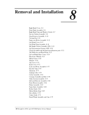
Release the tension from the roller support (item 4) and remove the support. 8. Remove the spring hook (T-15) (item 6). 1* 3* 4* 1* 6 3* 5 2* 7 7 * These items do not need to Figure 20. 6. Remove the ... For the following steps, refer to be removed when removing the Paper Entry Assembly or 7 the Center Guide Figure 20: Miscellaneous Parts 8 C607420b 8-22 HP DesignJets 1050C and 1055CM Printers Service Manual Release the sensor cable from the left side of the spring off the spring hook (item 6). 9. Remove the two T-15 screws (item...
Release the tension from the roller support (item 4) and remove the support. 8. Remove the spring hook (T-15) (item 6). 1* 3* 4* 1* 6 3* 5 2* 7 7 * These items do not need to Figure 20. 6. Remove the ... For the following steps, refer to be removed when removing the Paper Entry Assembly or 7 the Center Guide Figure 20: Miscellaneous Parts 8 C607420b 8-22 HP DesignJets 1050C and 1055CM Printers Service Manual Release the sensor cable from the left side of the spring off the spring hook (item 6). 9. Remove the two T-15 screws (item...

Service Manual
Page 245
WARNING Removal Switch off the printer and remove the power cord. 1. "Left Hand Cover" see page 8-13. 2. Removal and Installation Tensioner Refer to Figure 33 to Figure 33). 2 3 1 C607415 Figure 33: Tensioner Assembly HP DesignJets 1050C and 1055CM Printers Service Manual 8-37 Remove the following 1. To release the tension on the belt (item 1) from the left hand side of the Printer, squeeze the spring (item 2) using the tensioner wedge clip (item 3) until you hear it click into place (refer to Figure 35.
WARNING Removal Switch off the printer and remove the power cord. 1. "Left Hand Cover" see page 8-13. 2. Removal and Installation Tensioner Refer to Figure 33 to Figure 33). 2 3 1 C607415 Figure 33: Tensioner Assembly HP DesignJets 1050C and 1055CM Printers Service Manual 8-37 Remove the following 1. To release the tension on the belt (item 1) from the left hand side of the Printer, squeeze the spring (item 2) using the tensioner wedge clip (item 3) until you hear it click into place (refer to Figure 35.

Service Manual
Page 246
... (item 3). 5 4 2 8-38 3 4 1 Figure 35: Tensioner Assembly HP DesignJets 1050C and 1055CM Printers Service Manual Remove the two T-15 screws (item 4) securing the tensioner assembly to Figure 35. 4. Remove the belt (item 1) from the belt (item 2) which is located in the tensioner assembly (item 3). 5. Remove the tensioner pulley (item 1) from the belt motor pulley (item 2) on the right hand...
... (item 3). 5 4 2 8-38 3 4 1 Figure 35: Tensioner Assembly HP DesignJets 1050C and 1055CM Printers Service Manual Remove the two T-15 screws (item 4) securing the tensioner assembly to Figure 35. 4. Remove the belt (item 1) from the belt (item 2) which is located in the tensioner assembly (item 3). 5. Remove the tensioner pulley (item 1) from the belt motor pulley (item 2) on the right hand...
Service Manual
Page 255
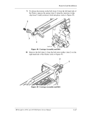
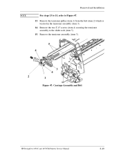
Remove the belt (item 1) from the left hand side of the Printer (refer to Figure 44). 2 3 1 C607415 Figure 44: Carriage Assembly and Belt 10. To release the tension on the belt (item 1) from the belt motor pulley (item 2) on the right hand side of the Printer, squeeze the spring (item 2) using the tensioner wedge clip (item 3) until you hear it click into place (refer to Figure 45) 2 1 Figure 45: Carriage Assembly and Belt HP DesignJets 1050C and 1055CM Printers Service Manual 8-47 Removal and Installation 9.
Remove the belt (item 1) from the left hand side of the Printer (refer to Figure 44). 2 3 1 C607415 Figure 44: Carriage Assembly and Belt 10. To release the tension on the belt (item 1) from the belt motor pulley (item 2) on the right hand side of the Printer, squeeze the spring (item 2) using the tensioner wedge clip (item 3) until you hear it click into place (refer to Figure 45) 2 1 Figure 45: Carriage Assembly and Belt HP DesignJets 1050C and 1055CM Printers Service Manual 8-47 Removal and Installation 9.
Service Manual
Page 257
Remove the tensioner assembly (item 3). 5 4 3 4 2 1 Figure 47: Carriage Assembly and Belt HP DesignJets 1050C and 1055CM Printers Service Manual 8-49 Remove the two T-15 screws (item 4) securing the tensioner assembly to Figure 47. 13. NOTE Removal and Installation For steps 13 to 15, refer to the slider rods (item 5). 15. Remove the tensioner pulley (item 1) from the belt (item 2) which is located in the tensioner assembly (item 3). 14.
Remove the tensioner assembly (item 3). 5 4 3 4 2 1 Figure 47: Carriage Assembly and Belt HP DesignJets 1050C and 1055CM Printers Service Manual 8-49 Remove the two T-15 screws (item 4) securing the tensioner assembly to Figure 47. 13. NOTE Removal and Installation For steps 13 to 15, refer to the slider rods (item 5). 15. Remove the tensioner pulley (item 1) from the belt (item 2) which is located in the tensioner assembly (item 3). 14.
Service Manual
Page 258
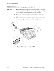
... off the slider rods. 17. Remove the belt (item 4) from retaining clips (item 5) underneath the carriage assembly. 3 2 1 4 5 Figure 48: Carriage Assembly and Belt 8-50 HP DesignJets 1050C and 1055CM Printers Service Manual Removal and Installation NOTE For the following steps, refer to Figure 48. When removing the carriage assembly (item 3) hold the rear bushing...
... off the slider rods. 17. Remove the belt (item 4) from retaining clips (item 5) underneath the carriage assembly. 3 2 1 4 5 Figure 48: Carriage Assembly and Belt 8-50 HP DesignJets 1050C and 1055CM Printers Service Manual Removal and Installation NOTE For the following steps, refer to Figure 48. When removing the carriage assembly (item 3) hold the rear bushing...

Service Manual
Page 260
...Color to Color Calibration ⇒ Page 5-16. n Roller Mark Position ⇒ Page 5-13. When installing the belt, make sure it is not twisted and is installed in the correct orientation as shown in the direction of the Tensioner... Assembly Figure 51: Belt Installation C607442 You must perform the following Service Calibrations after the installation of the Scan-Axis Motor NOTE Installed in Figure 51. Installed in the direction of the Carriage Assembly. n Service Station ⇒ Page 5-11. n Pen Alignment ⇒ Page 5-22. 8-52 HP DesignJets 1050C and 1055CM Printers...
...Color to Color Calibration ⇒ Page 5-16. n Roller Mark Position ⇒ Page 5-13. When installing the belt, make sure it is not twisted and is installed in the correct orientation as shown in the direction of the Tensioner... Assembly Figure 51: Belt Installation C607442 You must perform the following Service Calibrations after the installation of the Scan-Axis Motor NOTE Installed in Figure 51. Installed in the direction of the Carriage Assembly. n Service Station ⇒ Page 5-11. n Pen Alignment ⇒ Page 5-22. 8-52 HP DesignJets 1050C and 1055CM Printers...

Service Manual
Page 288
...16 MB of the electrical system. n Ink supply station: The Ink Supply Station is removed from damage. HP DesignJet 1050C Printer The HP DesignJet 1050C will have a network interface, 32 MB of whichever country this block. It also has the ability to ...Printer circuits and mechanical functions. Functional Overview Introduction This Chapter contains a simplified description of how the Printer operates. n Carriage: Connected to the printheads, this block supplies power to them, as well as monitoring and protecting them from the system, and eliminates the need for high tension...
...16 MB of the electrical system. n Ink supply station: The Ink Supply Station is removed from damage. HP DesignJet 1050C Printer The HP DesignJet 1050C will have a network interface, 32 MB of whichever country this block. It also has the ability to ...Printer circuits and mechanical functions. Functional Overview Introduction This Chapter contains a simplified description of how the Printer operates. n Carriage: Connected to the printheads, this block supplies power to them, as well as monitoring and protecting them from the system, and eliminates the need for high tension...
Service Manual
Page 318
...8-24 Roller Guide 8-66 Scan-axis Motor Assembly 8-33 Service Station Assembly 8-8 Tail Deflectors 8-23 Tensioner 8-37 Top Cover 8-31 Trailing Cable 8-39 Tubes System Assembly 8-53 Vacuum Fan 8-11 Window ...11 Scratching 6-24 Service Calibrations 1-3 Accuracy Calibration 5-6 Calibrations Backup 5-19 Carriage Height Calibration 5-24 Color to Color calibration 5-16 Entering 5-4 Line Sensor 5-9 Pen Alignment 5-22 Pen to Paper Spacing 5-15 Roller ...42 Overdrive Cleaning 4-37 Printer Model Type 4-35 Printhead Check 4-41 Release Info 4-32 Index-4 HP DesignJets 1050C and 1055CM Printers Service Manual
...8-24 Roller Guide 8-66 Scan-axis Motor Assembly 8-33 Service Station Assembly 8-8 Tail Deflectors 8-23 Tensioner 8-37 Top Cover 8-31 Trailing Cable 8-39 Tubes System Assembly 8-53 Vacuum Fan 8-11 Window ...11 Scratching 6-24 Service Calibrations 1-3 Accuracy Calibration 5-6 Calibrations Backup 5-19 Carriage Height Calibration 5-24 Color to Color calibration 5-16 Entering 5-4 Line Sensor 5-9 Pen Alignment 5-22 Pen to Paper Spacing 5-15 Roller ...42 Overdrive Cleaning 4-37 Printer Model Type 4-35 Printhead Check 4-41 Release Info 4-32 Index-4 HP DesignJets 1050C and 1055CM Printers Service Manual

Service Manual
Page 319
... 2-17 Continuable 2-2 Non-Continuable 2-2 Index T Tail Deflectors 8-23 Tensioner 8-37 Top Cover 8-31 Trailing Cable 8-39 Troubleshooting Shutdowns 1-7 System Error Codes 1-2 Tubes Guide Assemblies 7-32 Tubes Purge 4-28 Tubes System 8-53, 10-6 V Vacuum Fan 8-11 W Window 7-10, 8-30 Window Switch 8-7 Wiper 10-10 Worm marks 1-13 HP DesignJets 1050C and 1055CM Printers Service Manual Index-5
... 2-17 Continuable 2-2 Non-Continuable 2-2 Index T Tail Deflectors 8-23 Tensioner 8-37 Top Cover 8-31 Trailing Cable 8-39 Troubleshooting Shutdowns 1-7 System Error Codes 1-2 Tubes Guide Assemblies 7-32 Tubes Purge 4-28 Tubes System 8-53, 10-6 V Vacuum Fan 8-11 W Window 7-10, 8-30 Window Switch 8-7 Wiper 10-10 Worm marks 1-13 HP DesignJets 1050C and 1055CM Printers Service Manual Index-5