
Service Manual
Page 10
...Scan-axis Motor Assembly 8-33 Encoder Strip 8-34 Tensioner 8-37 Trailing Cable 8-39 Cutter Assembly 8-42 Carriage Assembly and Belt 8-44 Tubes System Assembly 8-53 Ink Leak Detector Assembly 8-60 Front Platen Assembly 8-62 Platen Assembly 8-63 Paper ... 8-71 Pinch-Wheel Assembly and Cam 8-73 Preventive Maintenance 9-1 Moisture on the Printer 9-2 Noisy Carriage Bushing 9-2 Belt Swelling 9-2 Cleaning the Printer 9-2 General Cleaning 9-2 Cleaning the Overdrive 9-3 Scheduled Maintenance 9-3 Level of Printer Usage 9-3 Scan-axis Maintenance 9-4 8 HP DesignJets 1050C and 1055CM Printers Service Manual
...Scan-axis Motor Assembly 8-33 Encoder Strip 8-34 Tensioner 8-37 Trailing Cable 8-39 Cutter Assembly 8-42 Carriage Assembly and Belt 8-44 Tubes System Assembly 8-53 Ink Leak Detector Assembly 8-60 Front Platen Assembly 8-62 Platen Assembly 8-63 Paper ... 8-71 Pinch-Wheel Assembly and Cam 8-73 Preventive Maintenance 9-1 Moisture on the Printer 9-2 Noisy Carriage Bushing 9-2 Belt Swelling 9-2 Cleaning the Printer 9-2 General Cleaning 9-2 Cleaning the Overdrive 9-3 Scheduled Maintenance 9-3 Level of Printer Usage 9-3 Scan-axis Maintenance 9-4 8 HP DesignJets 1050C and 1055CM Printers Service Manual

Service Manual
Page 93
After applying the Oil, perform the test again. 2 Check that the Carriage Belt and pulleys are installed correctly. 5 Replace the Scan-Axis Motor ⇒ Page 8-33. If the values obtained in the test are less than the Maximum ... Strip is clean. To resolve the problem, try the following: 1 Clean the Slider Rods and Apply Oil along the complete axis of the Slider Rods. HP DesignJets 1050C and 1055CM Printers Service Manual 4-19
After applying the Oil, perform the test again. 2 Check that the Carriage Belt and pulleys are installed correctly. 5 Replace the Scan-Axis Motor ⇒ Page 8-33. If the values obtained in the test are less than the Maximum ... Strip is clean. To resolve the problem, try the following: 1 Clean the Slider Rods and Apply Oil along the complete axis of the Slider Rods. HP DesignJets 1050C and 1055CM Printers Service Manual 4-19
Service Manual
Page 141
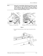
Figure 2 1 Disconnect the Ink Leak Detector Cable Connector from the back of the printer for correct calibration. HP DesignJets 1050C and 1055CM Printers Service Manual 5-25 Incorrect: never move using Carriage Assembly. NOTE Service Calibrations During the Carriage Height Calibration procedure the Carriage Assembly has to be moved along the length of the printer. Correct: move using the belt. Make sure that the Carriage Assembly is only ever moved by pulling the belt and never by direct contact with the carriage itself (See Figure 2 below).
Figure 2 1 Disconnect the Ink Leak Detector Cable Connector from the back of the printer for correct calibration. HP DesignJets 1050C and 1055CM Printers Service Manual 5-25 Incorrect: never move using Carriage Assembly. NOTE Service Calibrations During the Carriage Height Calibration procedure the Carriage Assembly has to be moved along the length of the printer. Correct: move using the belt. Make sure that the Carriage Assembly is only ever moved by pulling the belt and never by direct contact with the carriage itself (See Figure 2 below).

Service Manual
Page 144
... 9, if not you must lower the Carriage Assembly (step 8), and try again until a scraping sound is heard. 5-28 HP DesignJets 1050C and 1055CM Printers Service Manual NOTE: The screws should not be removed. 7 Using the belt, and beginning to the left hand side of the starting position (where the left hand edge of the paper...
... 9, if not you must lower the Carriage Assembly (step 8), and try again until a scraping sound is heard. 5-28 HP DesignJets 1050C and 1055CM Printers Service Manual NOTE: The screws should not be removed. 7 Using the belt, and beginning to the left hand side of the starting position (where the left hand edge of the paper...
Service Manual
Page 192
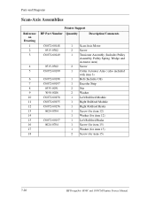
...Scan-Axis Assemblies Reference on Drawing 1 2 3 4 5 6 7 8 9 10 11 12 13 14 15 16 17 18 Printer Support HP Part Number Quantity Description/Comments C6072-60148 0515-0382 C6072-60149 0515-0382 C6072-60199 C6072-60198 C6072-60197 0535-0031 3050-0026 ... (also included with item 3) 1 Belt (Includes Oil) 1 Encoder Strip 2 Nut 2 Washer 1 Left Rollfeed Module 1 Right Rollfeed Module 1 Right Rollfeed Brake 1 Screw (for item 12) 1 Washer (for item 12) 1 Left Rollfeed Brake 1 Screw (for item 15) 1 Washer (for item 15) 2 Screw (for item 15) 7-20 HP DesignJets 1050C and 1055CM Printers Service Manual
...Scan-Axis Assemblies Reference on Drawing 1 2 3 4 5 6 7 8 9 10 11 12 13 14 15 16 17 18 Printer Support HP Part Number Quantity Description/Comments C6072-60148 0515-0382 C6072-60149 0515-0382 C6072-60199 C6072-60198 C6072-60197 0535-0031 3050-0026 ... (also included with item 3) 1 Belt (Includes Oil) 1 Encoder Strip 2 Nut 2 Washer 1 Left Rollfeed Module 1 Right Rollfeed Module 1 Right Rollfeed Brake 1 Screw (for item 12) 1 Washer (for item 12) 1 Left Rollfeed Brake 1 Screw (for item 15) 1 Washer (for item 15) 2 Screw (for item 15) 7-20 HP DesignJets 1050C and 1055CM Printers Service Manual
Service Manual
Page 209
... Cutter Assembly 8-42 Carriage Assembly and Belt 8-44 Tubes System Assembly 8-53 Ink Leak Detector Assembly 8-60 Front Platen Assembly 8-62 Platen Assembly 8-63 Paper Entry Assembly 8-64 Roller Guide 8-66 Media Holder Strip 8-69 Drive Roller 8-70 Center Guide 8-71 Pinch-Wheel Assembly and Cam 8-73 HP DesignJets 1050C and 1055CM Printers Service Manual 8-1
... Cutter Assembly 8-42 Carriage Assembly and Belt 8-44 Tubes System Assembly 8-53 Ink Leak Detector Assembly 8-60 Front Platen Assembly 8-62 Platen Assembly 8-63 Paper Entry Assembly 8-64 Roller Guide 8-66 Media Holder Strip 8-69 Drive Roller 8-70 Center Guide 8-71 Pinch-Wheel Assembly and Cam 8-73 HP DesignJets 1050C and 1055CM Printers Service Manual 8-1
Service Manual
Page 241
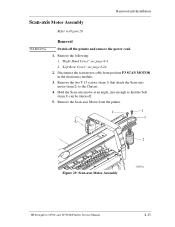
..." see page 8-4. 2. Remove the two T-15 screws (item 1) that the belt (item 3) can be taken off the printer and remove the power cord. 1. Remove the following: 1. Disconnect the scan motor cable from the printer. 1 1 3 2 Figure 29: Scan-axis Motor Assembly C60718 HP DesignJets 1050C and 1055CM Printers Service Manual 8-33 Hold the Scan-axis motor at an...
..." see page 8-4. 2. Remove the two T-15 screws (item 1) that the belt (item 3) can be taken off the printer and remove the power cord. 1. Remove the following: 1. Disconnect the scan motor cable from the printer. 1 1 3 2 Figure 29: Scan-axis Motor Assembly C60718 HP DesignJets 1050C and 1055CM Printers Service Manual 8-33 Hold the Scan-axis motor at an...

Service Manual
Page 245
"Left Hand Cover" see page 8-13. 2. Removal and Installation Tensioner Refer to Figure 33 to Figure 33). 2 3 1 C607415 Figure 33: Tensioner Assembly HP DesignJets 1050C and 1055CM Printers Service Manual 8-37 WARNING Removal Switch off the printer and remove the power cord. 1. To release the tension on the belt (item 1) from the left hand side of the Printer, squeeze the spring (item 2) using the tensioner wedge clip (item 3) until you hear it click into place (refer to Figure 35. Remove the following 1.
"Left Hand Cover" see page 8-13. 2. Removal and Installation Tensioner Refer to Figure 33 to Figure 33). 2 3 1 C607415 Figure 33: Tensioner Assembly HP DesignJets 1050C and 1055CM Printers Service Manual 8-37 WARNING Removal Switch off the printer and remove the power cord. 1. To release the tension on the belt (item 1) from the left hand side of the Printer, squeeze the spring (item 2) using the tensioner wedge clip (item 3) until you hear it click into place (refer to Figure 35. Remove the following 1.

Service Manual
Page 246
Remove the two T-15 screws (item 4) securing the tensioner assembly to Figure 35. 4. Remove the tensioner assembly (item 3). 5 4 2 8-38 3 4 1 Figure 35: Tensioner Assembly HP DesignJets 1050C and 1055CM Printers Service Manual Remove the belt (item 1) from the belt (item 2) which is located in the tensioner assembly (item 3). 5. Removal and Installation 3. Remove the tensioner pulley (item 1) from the...
Remove the two T-15 screws (item 4) securing the tensioner assembly to Figure 35. 4. Remove the tensioner assembly (item 3). 5 4 2 8-38 3 4 1 Figure 35: Tensioner Assembly HP DesignJets 1050C and 1055CM Printers Service Manual Remove the belt (item 1) from the belt (item 2) which is located in the tensioner assembly (item 3). 5. Removal and Installation 3. Remove the tensioner pulley (item 1) from the...

Service Manual
Page 252
Printhead tube connector Figure 41: Carriage Assembly and Belt 8-44 HP DesignJets 1050C and 1055CM Printers Service Manual "Right Hand Cover" see page 8-31. 2. Move the carriage to a position where you can access the printhead tube connector (refer to Figure 51. Remove the following: 1. "Top Cover" see page 8-4. 3. Removal and Installation Carriage Assembly and Belt Refer to Figure 41 to Figure 41). "Left Hand Cover" see page 8-13. 2. WARNING Removal Switch off the printer and remove the power cord. 1.
Printhead tube connector Figure 41: Carriage Assembly and Belt 8-44 HP DesignJets 1050C and 1055CM Printers Service Manual "Right Hand Cover" see page 8-31. 2. Move the carriage to a position where you can access the printhead tube connector (refer to Figure 51. Remove the following: 1. "Top Cover" see page 8-4. 3. Removal and Installation Carriage Assembly and Belt Refer to Figure 41 to Figure 41). "Left Hand Cover" see page 8-13. 2. WARNING Removal Switch off the printer and remove the power cord. 1.

Service Manual
Page 253
Remove the printhead tube connector (refer to Figure 42. 3. NOTE Removal and Installation For steps 3 and 4, refer to Figure 42). View from the rear c. Pull here Figure 42: Carriage Assembly and Belt 5. Loosen this screw a. Loosen the retaining screw T-9 at the back of the printhead tube connector. 4. Push in here b. Push in here Printhead tube connector a. HP DesignJets 1050C and 1055CM Printers Service Manual 8-45 Move the Printhead tube connector to a safe position.
Remove the printhead tube connector (refer to Figure 42. 3. NOTE Removal and Installation For steps 3 and 4, refer to Figure 42). View from the rear c. Pull here Figure 42: Carriage Assembly and Belt 5. Loosen this screw a. Loosen the retaining screw T-9 at the back of the printhead tube connector. 4. Push in here b. Push in here Printhead tube connector a. HP DesignJets 1050C and 1055CM Printers Service Manual 8-45 Move the Printhead tube connector to a safe position.
Service Manual
Page 254
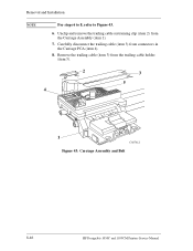
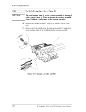
Unclip and remove the trailing cable restraining clip (item 2) from connectors in the Carriage PCA (item 4). 8. Carefully disconnect the trailing cable (item 3) from the Carriage Assembly (item 1). 7. Remove the trailing cable (item 3) from the trailing cable holder (item 5). 2 4 3 5 1 C607412 Figure 43: Carriage Assembly and Belt 8-46 HP DesignJets 1050C and 1055CM Printers Service Manual Removal and Installation NOTE For steps 6 to 8, refer to Figure 43. 6.
Unclip and remove the trailing cable restraining clip (item 2) from connectors in the Carriage PCA (item 4). 8. Carefully disconnect the trailing cable (item 3) from the Carriage Assembly (item 1). 7. Remove the trailing cable (item 3) from the trailing cable holder (item 5). 2 4 3 5 1 C607412 Figure 43: Carriage Assembly and Belt 8-46 HP DesignJets 1050C and 1055CM Printers Service Manual Removal and Installation NOTE For steps 6 to 8, refer to Figure 43. 6.
Service Manual
Page 255
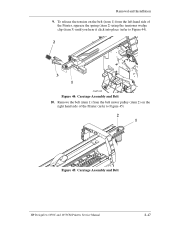
Remove the belt (item 1) from the belt motor pulley (item 2) on the belt (item 1) from the left hand side of the Printer (refer to Figure 44). 2 3 1 C607415 Figure 44: Carriage Assembly and Belt 10. To release the tension on the right hand side of the Printer, squeeze the spring (item 2) using the tensioner wedge clip (item 3) until you hear it click into place (refer to Figure 45) 2 1 Figure 45: Carriage Assembly and Belt HP DesignJets 1050C and 1055CM Printers Service Manual 8-47 Removal and Installation 9.
Remove the belt (item 1) from the belt motor pulley (item 2) on the belt (item 1) from the left hand side of the Printer (refer to Figure 44). 2 3 1 C607415 Figure 44: Carriage Assembly and Belt 10. To release the tension on the right hand side of the Printer, squeeze the spring (item 2) using the tensioner wedge clip (item 3) until you hear it click into place (refer to Figure 45) 2 1 Figure 45: Carriage Assembly and Belt HP DesignJets 1050C and 1055CM Printers Service Manual 8-47 Removal and Installation 9.
Service Manual
Page 257
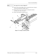
Remove the two T-15 screws (item 4) securing the tensioner assembly to Figure 47. 13. Remove the tensioner assembly (item 3). 5 4 3 4 2 1 Figure 47: Carriage Assembly and Belt HP DesignJets 1050C and 1055CM Printers Service Manual 8-49 NOTE Removal and Installation For steps 13 to 15, refer to the slider rods (item 5). 15. Remove the tensioner pulley (item 1) from the belt (item 2) which is located in the tensioner assembly (item 3). 14.
Remove the two T-15 screws (item 4) securing the tensioner assembly to Figure 47. 13. Remove the tensioner assembly (item 3). 5 4 3 4 2 1 Figure 47: Carriage Assembly and Belt HP DesignJets 1050C and 1055CM Printers Service Manual 8-49 NOTE Removal and Installation For steps 13 to 15, refer to the slider rods (item 5). 15. Remove the tensioner pulley (item 1) from the belt (item 2) which is located in the tensioner assembly (item 3). 14.
Service Manual
Page 258
... 4) from the carriage assembly by sliding it from retaining clips (item 5) underneath the carriage assembly. 3 2 1 4 5 Figure 48: Carriage Assembly and Belt 8-50 HP DesignJets 1050C and 1055CM Printers Service Manual Remove the carriage assembly (item 3) by releasing it off the slider rods. 17. When removing the carriage assembly (item 3) hold the rear bushing ...
... 4) from the carriage assembly by sliding it from retaining clips (item 5) underneath the carriage assembly. 3 2 1 4 5 Figure 48: Carriage Assembly and Belt 8-50 HP DesignJets 1050C and 1055CM Printers Service Manual Remove the carriage assembly (item 3) by releasing it off the slider rods. 17. When removing the carriage assembly (item 3) hold the rear bushing ...

Service Manual
Page 260
...8658; Page 5-22. 8-52 HP DesignJets 1050C and 1055CM Printers Service Manual When installing the belt, make sure it is not twisted and is installed in the correct orientation as shown in the direction of the Tensioner Assembly Figure 51: Belt Installation C607442 You must perform the ...following Service Calibrations after the installation of the Carriage Assembly. n Roller Mark Position ⇒ Page 5-13. Removal and Installation 3. n Color to Color Calibration ⇒ Page 5-16. Installed...
...8658; Page 5-22. 8-52 HP DesignJets 1050C and 1055CM Printers Service Manual When installing the belt, make sure it is not twisted and is installed in the correct orientation as shown in the direction of the Tensioner Assembly Figure 51: Belt Installation C607442 You must perform the ...following Service Calibrations after the installation of the Carriage Assembly. n Roller Mark Position ⇒ Page 5-13. Removal and Installation 3. n Color to Color Calibration ⇒ Page 5-16. Installed...

Service Manual
Page 283
9 Preventive Maintenance 9 Moisture on the Printer 9-2 Noisy Carriage Bushing 9-2 Belt Swelling 9-2 Cleaning the Printer 9-2 General Cleaning 9-2 Cleaning the Overdrive 9-3 Scheduled Maintenance 9-3 Level of Printer Usage 9-3 Scan-axis Maintenance 9-4 HP DesignJets 1050C and 1055CM Printers Service Manual 9-1
9 Preventive Maintenance 9 Moisture on the Printer 9-2 Noisy Carriage Bushing 9-2 Belt Swelling 9-2 Cleaning the Printer 9-2 General Cleaning 9-2 Cleaning the Overdrive 9-3 Scheduled Maintenance 9-3 Level of Printer Usage 9-3 Scan-axis Maintenance 9-4 HP DesignJets 1050C and 1055CM Printers Service Manual 9-1
Service Manual
Page 284
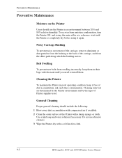
... Printer dry with a soft lint-free cloth. 9-2 HP DesignJets 1050C and 1055CM Printers Service Manual Belt Swelling To prevent new belts from moisture condensation, turn the Printer Off, and, using the main roller as a reference, wait until the Printer is completely dry before using it free of the Printer ...remove aluminum or dust particles from the slider path along which the bushing moves. Preventive Maintenance Preventive Maintenance Moisture on the Printer Users should include the following: 1 Blow away dust accumulation with compressed air if available. 2 Clean the outer surface ...
... Printer dry with a soft lint-free cloth. 9-2 HP DesignJets 1050C and 1055CM Printers Service Manual Belt Swelling To prevent new belts from moisture condensation, turn the Printer Off, and, using the main roller as a reference, wait until the Printer is completely dry before using it free of the Printer ...remove aluminum or dust particles from the slider path along which the bushing moves. Preventive Maintenance Preventive Maintenance Moisture on the Printer Users should include the following: 1 Blow away dust accumulation with compressed air if available. 2 Clean the outer surface ...
Service Manual
Page 315
... 4-42 Belt 8-44 Belt Swelling 9-2 C Calibrations Backup 5-19 Cam 8-73 Cap 10-10 Carriage Assembly 7-18, 8-44 Carriage Height Calibration 5-24 Carriage Interconnect Wiper 3-18 Center Guide 7-30, 8-71 Cleaning General 9-2 Overdrive 9-3 Printer 9-2 Clutch Assembly 7-16, 8-21 Color Accuracy Configuration 6-23 Color changes when stacking 1-10 Color differences 1-11 Color to Color calibration 5-...Strip 8-34 Environmental Specifications 10-14 F Front Panel 8-6, 10-4 Front Panel Display 3-7 Front Platen Assembly 8-62 Front-Panel Menu 1-15 HP DesignJets 1050C and 1055CM Printers Service Manual Index-1
... 4-42 Belt 8-44 Belt Swelling 9-2 C Calibrations Backup 5-19 Cam 8-73 Cap 10-10 Carriage Assembly 7-18, 8-44 Carriage Height Calibration 5-24 Carriage Interconnect Wiper 3-18 Center Guide 7-30, 8-71 Cleaning General 9-2 Overdrive 9-3 Printer 9-2 Clutch Assembly 7-16, 8-21 Color Accuracy Configuration 6-23 Color changes when stacking 1-10 Color differences 1-11 Color to Color calibration 5-...Strip 8-34 Environmental Specifications 10-14 F Front Panel 8-6, 10-4 Front Panel Display 3-7 Front Platen Assembly 8-62 Front-Panel Menu 1-15 HP DesignJets 1050C and 1055CM Printers Service Manual Index-1
Service Manual
Page 318
Index Removing Air Pressurization System 8-20 Back Cover 8-32 Belt 8-44 Carriage Assembly 8-44 Center Guide 8-71 Clutch Assembly 8-... Scratches on prints 1-11 Scratching 6-24 Service Calibrations 1-3 Accuracy Calibration 5-6 Calibrations Backup 5-19 Carriage Height Calibration 5-24 Color to Color calibration 5-16 Entering 5-4 Line Sensor 5-9 Pen Alignment 5-22 Pen to Paper Spacing 5-15 Roller Mark Position 5-13 ... 4-26 Mon. Mode Baud Sel. 4-42 Overdrive Cleaning 4-37 Printer Model Type 4-35 Printhead Check 4-41 Release Info 4-32 Index-4 HP DesignJets 1050C and 1055CM Printers Service Manual
Index Removing Air Pressurization System 8-20 Back Cover 8-32 Belt 8-44 Carriage Assembly 8-44 Center Guide 8-71 Clutch Assembly 8-... Scratches on prints 1-11 Scratching 6-24 Service Calibrations 1-3 Accuracy Calibration 5-6 Calibrations Backup 5-19 Carriage Height Calibration 5-24 Color to Color calibration 5-16 Entering 5-4 Line Sensor 5-9 Pen Alignment 5-22 Pen to Paper Spacing 5-15 Roller Mark Position 5-13 ... 4-26 Mon. Mode Baud Sel. 4-42 Overdrive Cleaning 4-37 Printer Model Type 4-35 Printhead Check 4-41 Release Info 4-32 Index-4 HP DesignJets 1050C and 1055CM Printers Service Manual


