
Owner's Manual
Page 6
... Certificate Glossary Warranty Card Specifications Sheet 6 En Please check contents before discarding or allowing your panel. Shipped with your installer to the Flat Panel Displays The Pioneer Flat Panel Display models include the 60-inch PRO-141FD and the 50-inch PRO-101FD (screen sizes measured diagonally). Below is a list of all accessories shipped with both models...
... Certificate Glossary Warranty Card Specifications Sheet 6 En Please check contents before discarding or allowing your panel. Shipped with your installer to the Flat Panel Displays The Pioneer Flat Panel Display models include the 60-inch PRO-141FD and the 50-inch PRO-101FD (screen sizes measured diagonally). Below is a list of all accessories shipped with both models...
Owner's Manual
Page 7
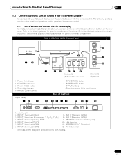
... 9 7 6 3 45 67 8 PRO-101FD (Bottom of Panel 1 2 1 - Bezel (some call it the front frame) Back of the Panel 4 56 78 9 10 11 12 (from the panel buttons or with more buttons on the rear panel are common to identify back ports and ...terminals only, check the terminal position sheet located near the panel's terminal compartment. IR REPEATER OUT terminal 12 - STANDBY/ON button 7 - PRO-141FD/PRO-101FD: Face of the rear panel) PRO-141FD (Right side) 6 - INPUT buttons 9 - INPUT 1 terminal (Video) 2 - INPUT 2 terminals (Component, Y, ...
... 9 7 6 3 45 67 8 PRO-101FD (Bottom of Panel 1 2 1 - Bezel (some call it the front frame) Back of the Panel 4 56 78 9 10 11 12 (from the panel buttons or with more buttons on the rear panel are common to identify back ports and ...terminals only, check the terminal position sheet located near the panel's terminal compartment. IR REPEATER OUT terminal 12 - STANDBY/ON button 7 - PRO-141FD/PRO-101FD: Face of the rear panel) PRO-141FD (Right side) 6 - INPUT buttons 9 - INPUT 1 terminal (Video) 2 - INPUT 2 terminals (Component, Y, ...
Owner's Manual
Page 12
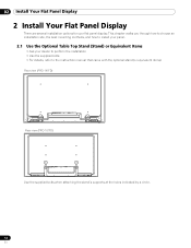
..., the best mounting methods, and how to the instruction manual that came with the optional stand (or equivalent items) Rear view (PRO-141FD) Rear view (PRO-101FD) Use the supplied bolts when attaching the stand's supports at the holes indicated by a circle. 12 En 02 Install Your Flat... Panel Display 2 Install Your Flat Panel Display There are several installation options for your dealer to perform the installation • Use the supplied bolts • For details, refer to install your panel. 2.1 Use the Optional Table Top Stand (Stand) or...
..., the best mounting methods, and how to the instruction manual that came with the optional stand (or equivalent items) Rear view (PRO-141FD) Rear view (PRO-101FD) Use the supplied bolts when attaching the stand's supports at the holes indicated by a circle. 12 En 02 Install Your Flat... Panel Display 2 Install Your Flat Panel Display There are several installation options for your dealer to perform the installation • Use the supplied bolts • For details, refer to install your panel. 2.1 Use the Optional Table Top Stand (Stand) or...
Owner's Manual
Page 13
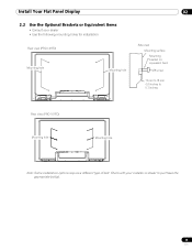
Install Your Flat Panel Display 02 2.2 Use the Optional Brackets or Equivalent Items • Consult your installer or dealer to 0.7 inches) Rear view (PRO-101FD) Mounting hole Mounting hole Note: Some installation options require a different type of bolt. Check with your dealer • Use the following mounting holes for installation Rear view (PRO-141FD) Mounting hole Mounting hole Side view Mounting surface Mounting bracket (or equivalent item) M8 screw 12 mm to 18 mm (0.5 inches to purchase the appropriate bolt(s). 13 En
Install Your Flat Panel Display 02 2.2 Use the Optional Brackets or Equivalent Items • Consult your installer or dealer to 0.7 inches) Rear view (PRO-101FD) Mounting hole Mounting hole Note: Some installation options require a different type of bolt. Check with your dealer • Use the following mounting holes for installation Rear view (PRO-141FD) Mounting hole Mounting hole Side view Mounting surface Mounting bracket (or equivalent item) M8 screw 12 mm to 18 mm (0.5 inches to purchase the appropriate bolt(s). 13 En
Owner's Manual
Page 14
... at least two people to lift and move the flat panel display by holding only a single handle or by dragging the panel by its handles. (PRO-141FD) (PRO-101FD) Note: Do not use the handles to hang the flat panel display or as anchors to prevent the panel from strong lighting sources For specific cautions and safety...
... at least two people to lift and move the flat panel display by holding only a single handle or by dragging the panel by its handles. (PRO-141FD) (PRO-101FD) Note: Do not use the handles to hang the flat panel display or as anchors to prevent the panel from strong lighting sources For specific cautions and safety...
Owner's Manual
Page 15
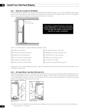
... mm (0.5 inches to 0.7 inches) M8 (PRO-141FD) To stabilize the flat panel display on a table or platform, use the metal fittings and screws supplied with the optional stand to anchor the panel to a wall or other solid support structure. Anchor the Panel When Using a Stand When using the optional stand...into the wall or support structure. 3 ) Run cords between the hooks and the fittings. 1.Hook 4 ) Tighten the cords until the panel is attached. The following sections provide instructions for the cord. The hardware size and strength depends on the back of the anchoring surface. ...
... mm (0.5 inches to 0.7 inches) M8 (PRO-141FD) To stabilize the flat panel display on a table or platform, use the metal fittings and screws supplied with the optional stand to anchor the panel to a wall or other solid support structure. Anchor the Panel When Using a Stand When using the optional stand...into the wall or support structure. 3 ) Run cords between the hooks and the fittings. 1.Hook 4 ) Tighten the cords until the panel is attached. The following sections provide instructions for the cord. The hardware size and strength depends on the back of the anchoring surface. ...
Owner's Manual
Page 16
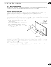
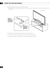
.... 1 ) Mark locations for metal fittings and screws on the back edge of the table using the panel stand to determine placement. (PRO-141FD) Wood screw (commercially available, 4 mm x 20 mm (5/32 inch x 13/16 inch) min.) Falling prevention metal fitting (supplied with the optional ...stand) 2 ) Drill holes in the table or platform edge at the marked locations. 3 ) Lift panel into place with the assistance with at least...
.... 1 ) Mark locations for metal fittings and screws on the back edge of the table using the panel stand to determine placement. (PRO-141FD) Wood screw (commercially available, 4 mm x 20 mm (5/32 inch x 13/16 inch) min.) Falling prevention metal fitting (supplied with the optional ...stand) 2 ) Drill holes in the table or platform edge at the marked locations. 3 ) Lift panel into place with the assistance with at least...
Owner's Manual
Page 19
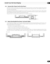
...verifying that works for the location. PRO-141FD PRO-101FD 19 En As long as the flat panel display is plugged in to be used for the noise filter between the panel and outlet • Placement of the plasma as well as necessary. Always connect the panel's power cord to mandatory FCC standards.... Use the cable clamps as saves energy. When the flat panel display is not going to an outlet, ...
...verifying that works for the location. PRO-141FD PRO-101FD 19 En As long as the flat panel display is plugged in to be used for the noise filter between the panel and outlet • Placement of the plasma as well as necessary. Always connect the panel's power cord to mandatory FCC standards.... Use the cable clamps as saves energy. When the flat panel display is not going to an outlet, ...
Owner's Manual
Page 21
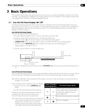
... or when powered off, the display continues to draw some power as long as powering on the side (PRO-141FD) or rear (PRO-101FD) of how the indicators light. Power Standby Indicator Indicator Flat Panel Display Status Panel's power cord is disconnected or the power cord is connected but allows the remote control to flat...
... or when powered off, the display continues to draw some power as long as powering on the side (PRO-141FD) or rear (PRO-101FD) of how the indicators light. Power Standby Indicator Indicator Flat Panel Display Status Panel's power cord is disconnected or the power cord is connected but allows the remote control to flat...
Owner's Manual
Page 23
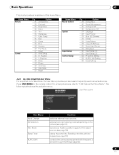
... table shows the available menus. Position V. USER MENU FLAT PANEL DISPLAY User Menu screen Input Change AV Selection Film Mode Sleep Timer KURO LINK : Standard : Off Exit User Menu Input Change AV Selection Film Mode Sleep Timer KURO LINK Function switches external input sources selects from eight viewing modes... 38 27 53 26 26 53 53 33 36 37 Option AV Selection Contrast Brightness Color Tint Sharpness Color Temp Red Green Blue Gamma Pro Adjust Reset Auto Setup H. For actual procedures, refer to frequently used menus/submenus. Position Clock Phase Auto Size Side Mask Reset Home...
... table shows the available menus. Position V. USER MENU FLAT PANEL DISPLAY User Menu screen Input Change AV Selection Film Mode Sleep Timer KURO LINK : Standard : Off Exit User Menu Input Change AV Selection Film Mode Sleep Timer KURO LINK Function switches external input sources selects from eight viewing modes... 38 27 53 26 26 53 53 33 36 37 Option AV Selection Contrast Brightness Color Tint Sharpness Color Temp Red Green Blue Gamma Pro Adjust Reset Auto Setup H. For actual procedures, refer to frequently used menus/submenus. Position Clock Phase Auto Size Side Mask Reset Home...

Owner's Manual
Page 26
.... 04 Basic Picture Adjustment For standard picture adjustments, follow the steps below . AV Selection Contrast Brightness Color Tint Sharpness Color Temp Red Green Blue Gamma Pro Adjust Reset Picture : STANDARD : 40 : 0 : 0 : 0 : 0 : Mid : 0 : 0 : 0 : 3 4 ) Use the arrow buttons (/) to adjust to be adjusted. Although repositioning is unavailable. Use the arrow buttons...
.... 04 Basic Picture Adjustment For standard picture adjustments, follow the steps below . AV Selection Contrast Brightness Color Tint Sharpness Color Temp Red Green Blue Gamma Pro Adjust Reset Picture : STANDARD : 40 : 0 : 0 : 0 : 0 : Mid : 0 : 0 : 0 : 3 4 ) Use the arrow buttons (/) to adjust to be adjusted. Although repositioning is unavailable. Use the arrow buttons...
Owner's Manual
Page 32
...environment. from a PC). option, set the AV Selection to exit the menu. Also, the Game Control Pref. To have the panel store your flat panel display, use an external input (unless the sourse is selected, images are reproduced based on the menu. To activate the Game Control ... room • USER: allows customizing the settings for each input source 5.1.4 Set the Panel to Recognize a Game Console When adding a game console to your Game preference, follow the steps below . 1 ) Access Pro Adjust through the Home Menu Another method for choosing an AV Selection uses the Home Menu...
...environment. from a PC). option, set the AV Selection to exit the menu. Also, the Game Control Pref. To have the panel store your flat panel display, use an external input (unless the sourse is selected, images are reproduced based on the menu. To activate the Game Control ... room • USER: allows customizing the settings for each input source 5.1.4 Set the Panel to Recognize a Game Console When adding a game console to your Game preference, follow the steps below . 1 ) Access Pro Adjust through the Home Menu Another method for choosing an AV Selection uses the Home Menu...
Owner's Manual
Page 35
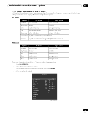
... preferences, often the source causes unanticipated image changes. Picture AV Selection Contrast Brightness Color Tint Sharpness Color Temp Gamma Pro Adjust Reset Exit : STANDARD : +38 : -7 : -6 : 5 : 4 : Mid : 5 (AV source) 35 En Your flat panel display offers several adjustment options. Use the arrow buttons to highlight an option then press ENTER. 3 ) Select an option...
... preferences, often the source causes unanticipated image changes. Picture AV Selection Contrast Brightness Color Tint Sharpness Color Temp Gamma Pro Adjust Reset Exit : STANDARD : +38 : -7 : -6 : 5 : 4 : Mid : 5 (AV source) 35 En Your flat panel display offers several adjustment options. Use the arrow buttons to highlight an option then press ENTER. 3 ) Select an option...
Owner's Manual
Page 36
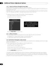
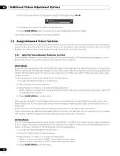
This section explores the value offered through Pioneer's Pro Adjust support, top quality blacks, better balanced whites, and overall color improvements. 5.3.1 Adjust for Screen Masking (black bars on sides) Screen Masks fill areas on , the panel automatically detects images containing side masks ... basic adjustments explained earlier in a 4:3 image. Note: Reset returns all adjustments are hidden. These responses reduce afterimage concerns. To allow the panel to detect side masks, follow the steps below . 1 ) Access Side Mask through the Screen menu. 2 ) Select HD Wide Mode from...
This section explores the value offered through Pioneer's Pro Adjust support, top quality blacks, better balanced whites, and overall color improvements. 5.3.1 Adjust for Screen Masking (black bars on sides) Screen Masks fill areas on , the panel automatically detects images containing side masks ... basic adjustments explained earlier in a 4:3 image. Note: Reset returns all adjustments are hidden. These responses reduce afterimage concerns. To allow the panel to detect side masks, follow the steps below . 1 ) Access Side Mask through the Screen menu. 2 ) Select HD Wide Mode from...
Owner's Manual
Page 38
... Select PureCinema from the submenu. 3 ) Press HOME MENU to exit the menu. 5.3.4 Select a PureCinema Level for High Quality Image Pioneer's PureCinema automatically detects and analyses a film-based source (originally encoded at 24 frames per second for smooth and vivid playback Smooth (not...(e.g., movies) having 24 frames per second) then recreates each frame for your HD material, follow the directions below . 1 ) Access Pro Adjust through 5 from the Pro Adjust menu. 3 ) Select Film Mode or Text Optimization, depending on the material. 4 ) Select the desired parameter. Option R ...
... Select PureCinema from the submenu. 3 ) Press HOME MENU to exit the menu. 5.3.4 Select a PureCinema Level for High Quality Image Pioneer's PureCinema automatically detects and analyses a film-based source (originally encoded at 24 frames per second for smooth and vivid playback Smooth (not...(e.g., movies) having 24 frames per second) then recreates each frame for your HD material, follow the directions below . 1 ) Access Pro Adjust through 5 from the Pro Adjust menu. 3 ) Select Film Mode or Text Optimization, depending on the material. 4 ) Select the desired parameter. Option R ...

Owner's Manual
Page 39
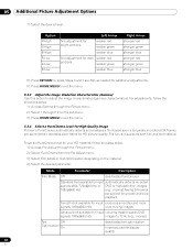
This setting applies only to exit the menu. To select the Intelligent Mode, follow the steps below. 1 ) Access Pro Adjust through the Picture menu. 2 ) Select Intelligent Mode from the Pro Adjust menu. 3 ) Select Mode 1 or Mode 2 (or Off ). 4 ) Select the desired parameter. Notes: Activating the Game Control Pref. This is normal and is...
This setting applies only to exit the menu. To select the Intelligent Mode, follow the steps below. 1 ) Access Pro Adjust through the Picture menu. 2 ) Select Intelligent Mode from the Pro Adjust menu. 3 ) Select Mode 1 or Mode 2 (or Off ). 4 ) Select the desired parameter. Notes: Activating the Game Control Pref. This is normal and is...

Owner's Manual
Page 40
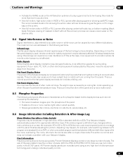
...Color Space options to exit the menu. To select the Picture Detail options, follow the steps below . 1 ) Access Pro Adjust through the Picture menu. 2 ) Select Color Detail from the Pro Adjust menu. 3 ) Select CTI or Color Space from the submenu. 3 ) Select DRE Picture, Black Level, ACL... or Enhancer Mode. 4 ) Select the desired parameter. To set the CTI and Color Space options, follow the steps below . 1 ) Access Pro Adjust through the Picture menu. 2 ) Select Picture Detail from the submenu. 4 ) Select the desired parameter. Option Parameter Description DRE Picture (emphasizes...
...Color Space options to exit the menu. To select the Picture Detail options, follow the steps below . 1 ) Access Pro Adjust through the Picture menu. 2 ) Select Color Detail from the Pro Adjust menu. 3 ) Select CTI or Color Space from the submenu. 3 ) Select DRE Picture, Black Level, ACL... or Enhancer Mode. 4 ) Select the desired parameter. To set the CTI and Color Space options, follow the steps below . 1 ) Access Pro Adjust through the Picture menu. 2 ) Select Picture Detail from the submenu. 4 ) Select the desired parameter. Option Parameter Description DRE Picture (emphasizes...

Owner's Manual
Page 41
...to fine adjust image coloring. To select the Noise Reduction options, follow the steps below . 1 ) Access Pro Adjust through the Picture menu. 2 ) Select Color Detail from the Pro Adjust menu. 3 ) Select Color Management from the Pro Adjust menu. 3 ) Select 3DNR, Field NR, Block NR or Mosquito NR. 4 ) Select the ... Note: This setting applies only to exit the menu. To set the Color Management option, follow the steps below . 1 ) Access Pro Adjust through the Picture menu. 2 ) Select Noise Reduction from the submenu. 4 ) Select the desired parameter. 5 ) Select the desired level.
...to fine adjust image coloring. To select the Noise Reduction options, follow the steps below . 1 ) Access Pro Adjust through the Picture menu. 2 ) Select Color Detail from the Pro Adjust menu. 3 ) Select Color Management from the Pro Adjust menu. 3 ) Select 3DNR, Field NR, Block NR or Mosquito NR. 4 ) Select the ... Note: This setting applies only to exit the menu. To set the Color Management option, follow the steps below . 1 ) Access Pro Adjust through the Picture menu. 2 ) Select Noise Reduction from the submenu. 4 ) Select the desired parameter. 5 ) Select the desired level.

Owner's Manual
Page 42
...separating brightness signals from color signals) High Mid No effect enhances 3DYC standard 3DYC Low moderate 3DYC I-P Mode (provides optimum conversion from the Pro Adjust menu. 3 ) Select 3DYC, I-P Mode, Drive Mode, Game Control Pref. option for operability (On) is unavailable for both video... Game Control Pref. 05 Additional Picture Adjustment Options 5 ) Press HOME MENU to input video signals. 5.3.10 Adjust Color Signals Your flat panel display features various color signal adjustment options: 3DYC, I-P Mode, Drive Mode, Game Control Pref., and Blue Only Mode. Note: This ...
...separating brightness signals from color signals) High Mid No effect enhances 3DYC standard 3DYC Low moderate 3DYC I-P Mode (provides optimum conversion from the Pro Adjust menu. 3 ) Select 3DYC, I-P Mode, Drive Mode, Game Control Pref. option for operability (On) is unavailable for both video... Game Control Pref. 05 Additional Picture Adjustment Options 5 ) Press HOME MENU to input video signals. 5.3.10 Adjust Color Signals Your flat panel display features various color signal adjustment options: 3DYC, I-P Mode, Drive Mode, Game Control Pref., and Blue Only Mode. Note: This ...
Owner's Manual
Page 81
.... This flat panel display automatically scales to the appropriate definition type. With the PRO-141FD/PRO-101FD, there are addressed in the following are typical effects and characteristics of a phosphor-based matrix display and as video noise or white noise, can cause uneven wear on the plasma cells. 8.4 ... high level of ultra-precision technology and undergo individual quality control. 81 En All Pioneer display panels are not covered by the Warranty: • Permanent residual images upon the phosphors of the panel • Existence of one or more than two hours at times. This is...
.... This flat panel display automatically scales to the appropriate definition type. With the PRO-141FD/PRO-101FD, there are addressed in the following are typical effects and characteristics of a phosphor-based matrix display and as video noise or white noise, can cause uneven wear on the plasma cells. 8.4 ... high level of ultra-precision technology and undergo individual quality control. 81 En All Pioneer display panels are not covered by the Warranty: • Permanent residual images upon the phosphors of the panel • Existence of one or more than two hours at times. This is...


