Owner Manual
Page 1
TX-8511 Audio Video Control Receiver Instruction Manual ===1 o= = o 6 I -:.' - - iCle,i.i.i.n.r.„ii,taei-,l,',..;C,-i....'n.:'.-..t".'i,,".,f-,„..-r,."*o-.-.!-.-l:f-k I 0 0 OO O = = =- EaliOhe:441-011 -24.4t-,`-- 7''';',10-C428 OOO European models Other models CONTENT ...,oadlelnam• • es 04- :; guide; .1 - 'P ki. ''1 I7s.-.!' --' ''. onnnectinanntecnonna- nse.ct-on4 - .!.'63inlctifg the ,i)bw ast :gperations- APEallt0 2 pppec4onf:gr;:,._ pn-:gropjzt 2•uRltei4iiZio6ofe-n.C.Ti. ONKYO.
TX-8511 Audio Video Control Receiver Instruction Manual ===1 o= = o 6 I -:.' - - iCle,i.i.i.n.r.„ii,taei-,l,',..;C,-i....'n.:'.-..t".'i,,".,f-,„..-r,."*o-.-.!-.-l:f-k I 0 0 OO O = = =- EaliOhe:441-011 -24.4t-,`-- 7''';',10-C428 OOO European models Other models CONTENT ...,oadlelnam• • es 04- :; guide; .1 - 'P ki. ''1 I7s.-.!' --' ''. onnnectinanntecnonna- nse.ct-on4 - .!.'63inlctifg the ,i)bw ast :gperations- APEallt0 2 pppec4onf:gr;:,._ pn-:gropjzt 2•uRltei4iiZio6ofe-n.C.Ti. ONKYO.
Owner Manual
Page 2
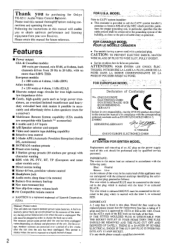
...coloured BLUE must be performed only by ASTA or BSI to the terminal in the plug which provides guidelines for purchasing Me Onkyo TX-8511 Audio Video Control Rlteiier. This period is shorter when the unit is fitted in this appliance may not correspond with the following...the mains lead are coloured in accordance with the coloured markings identifying the terminals in order to the point of Conformity We, ONKYO EUROPE ELECTRONICS GMBH INDUSTRIESTRASSE 18/20 82110 GERMERING. Please retain this manual thoroughlSriletore making connections and operating the unit. ATTENTION: POUR...
...coloured BLUE must be performed only by ASTA or BSI to the terminal in the plug which provides guidelines for purchasing Me Onkyo TX-8511 Audio Video Control Rlteiier. This period is shorter when the unit is fitted in this appliance may not correspond with the following...the mains lead are coloured in accordance with the coloured markings identifying the terminals in order to the point of Conformity We, ONKYO EUROPE ELECTRONICS GMBH INDUSTRIESTRASSE 18/20 82110 GERMERING. Please retain this manual thoroughlSriletore making connections and operating the unit. ATTENTION: POUR...
Owner Manual
Page 6
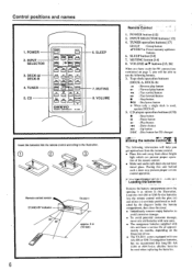
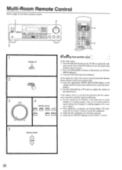
... or UM-3)-size batteries into the remote control according to use the following buttons. 3. O O (-3O Remote control sensor STAND-BY indicator 30' 30* TX-8511 approx. 5 m (16 feet) 6 RernOte'COntrol' ' 1. POWER button [12] 2. MUTING button [14] 8. The following information will help you ...tinted glass. iNnirorM?•ffp LwV/,i 4, 4w ?w, • Loading the batteries - fY±-OCJ-W1L75n 1=1 A CI CI (= 4se VOLUME C] ONKYO REMOTE CONTROLLER RC-MS 6. CI) player operation buttons (CD) • : Stop button II : Pause button :Play button 114 : Down button HI...
... or UM-3)-size batteries into the remote control according to use the following buttons. 3. O O (-3O Remote control sensor STAND-BY indicator 30' 30* TX-8511 approx. 5 m (16 feet) 6 RernOte'COntrol' ' 1. POWER button [12] 2. MUTING button [14] 8. The following information will help you ...tinted glass. iNnirorM?•ffp LwV/,i 4, 4w ?w, • Loading the batteries - fY±-OCJ-W1L75n 1=1 A CI CI (= 4se VOLUME C] ONKYO REMOTE CONTROLLER RC-MS 6. CI) player operation buttons (CD) • : Stop button II : Pause button :Play button 114 : Down button HI...
Owner Manual
Page 24
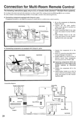
... Connect the sub room speaker cables to the TX-8511. 2. Do not make a mistake when connecting the units. A. Connecting components not equipped with Onkyo R I jacks Components mounted in SPEAKERS B TX-8511 24 Connecting block Emitter U 0 Power supply Lev... Speaker B (Sub Room) O Remote Sensor SUB ROOM Onkyo components (a) I 1. Emitter\ (e) SUB ROOM Connec block 4. ...
... Connect the sub room speaker cables to the TX-8511. 2. Do not make a mistake when connecting the units. A. Connecting components not equipped with Onkyo R I jacks Components mounted in SPEAKERS B TX-8511 24 Connecting block Emitter U 0 Power supply Lev... Speaker B (Sub Room) O Remote Sensor SUB ROOM Onkyo components (a) I 1. Emitter\ (e) SUB ROOM Connec block 4. ...
Owner Manual
Page 25
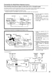
... Room) FM) Remote sensor HR-10 SUB ROOM 25 Components(b) Remote sensor Remote control- - Connect the components (b) to the speaker B terminal on the TX-8511. (0)) 3. Connecting components equipped with Onkyo R I jacks Components mounted in a rack should be sure to connect the units as described above or in the connection diagram below to the...
... Room) FM) Remote sensor HR-10 SUB ROOM 25 Components(b) Remote sensor Remote control- - Connect the components (b) to the speaker B terminal on the TX-8511. (0)) 3. Connecting components equipped with Onkyo R I jacks Components mounted in a rack should be sure to connect the units as described above or in the connection diagram below to the...
Owner Manual
Page 26
...the components are correctly connected. • Check that the MR OFF indicator on the remote control to page 6. • When operating a component not bearing Onkyo's R I jack, check that the emitter is not lit. 5 Remote control A VOLUME Mil V 26 the remote control is working properly. Press the... 1 Indicator off . (If the MR OFF indicator is working properly. nents cannot be controlled, check the following: • Use the controls On the TX-8511 in the main room to make the indi- cator go off A UR Off fi 1 2 SPEAKERS. Turn the VOLUME knob to pages 24 and 25...
...the components are correctly connected. • Check that the MR OFF indicator on the remote control to page 6. • When operating a component not bearing Onkyo's R I jack, check that the emitter is not lit. 5 Remote control A VOLUME Mil V 26 the remote control is working properly. Press the... 1 Indicator off . (If the MR OFF indicator is working properly. nents cannot be controlled, check the following: • Use the controls On the TX-8511 in the main room to make the indi- cator go off A UR Off fi 1 2 SPEAKERS. Turn the VOLUME knob to pages 24 and 25...


