Owner Manual
Page 5
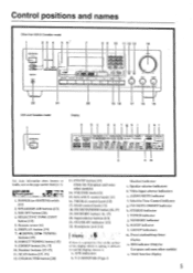
...i1l-\t"r?.m\t/I . TUNING buttons [15] 8. 1)1 RECI"l'UNING button [151 9. BALANCE control knob [131 16. FM MUTE/NIODE button [16, 171 19. Multi function display 5 Number buttons 115-17] 11. CHARACTER button [20] 13. Speaker selector indicators d. STEREO indicator i. Control positions and names Other than USA & Canadian model 1... Ira 4.0. 0•100, MK 0 8 9 10 11 12 13 14 Is PIO u CO i Ttit!) ) 4.1•04.400 TX 5,, 22 21 USA and Canadian model 20 19 18 17 16 15 Display a d e f ah i k I -APRRR STEREO MODE ''•MOOE [ULM MU WIN I \tp\i. 11/ GROUP ABC SLEEP...
...i1l-\t"r?.m\t/I . TUNING buttons [15] 8. 1)1 RECI"l'UNING button [151 9. BALANCE control knob [131 16. FM MUTE/NIODE button [16, 171 19. Multi function display 5 Number buttons 115-17] 11. CHARACTER button [20] 13. Speaker selector indicators d. STEREO indicator i. Control positions and names Other than USA & Canadian model 1... Ira 4.0. 0•100, MK 0 8 9 10 11 12 13 14 Is PIO u CO i Ttit!) ) 4.1•04.400 TX 5,, 22 21 USA and Canadian model 20 19 18 17 16 15 Display a d e f ah i k I -APRRR STEREO MODE ''•MOOE [ULM MU WIN I \tp\i. 11/ GROUP ABC SLEEP...
Owner Manual
Page 12
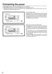
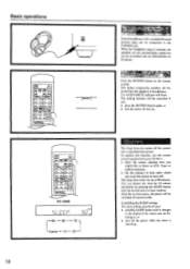
... status. When the SYSTEM switch is set to put the unit in power-on status (the unit can be operated and its display is lit). and Canadian models: Plugging the TX-851 l's power cord into an AC outlet, press the SYSTEM switch to ON, pressing the POWER button on the remote control... 000 U.S. The remote control cannot be sure that all connections have been trade properly. • Before turning on the power, be used to operate the TX-8511 if the SYSTEM switch is not set to the stand-by status (the STAND-BY indicator is used in the same way as com- Pressing...
... status. When the SYSTEM switch is set to put the unit in power-on status (the unit can be operated and its display is lit). and Canadian models: Plugging the TX-851 l's power cord into an AC outlet, press the SYSTEM switch to ON, pressing the POWER button on the remote control... 000 U.S. The remote control cannot be sure that all connections have been trade properly. • Before turning on the power, be used to operate the TX-8511 if the SYSTEM switch is not set to the stand-by status (the STAND-BY indicator is used in the same way as com- Pressing...
Owner Manual
Page 13
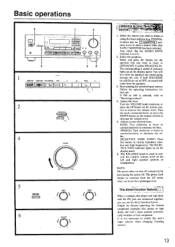
... SPEAKERS (A and B) are connected together, you can use for that component. Turn the VOLUME knob clockwise or press the UP button on the display panel. Simply by just turning the power off. r .tfklit . . Confirm that the AUDIO 'MUTE indicator is used to switch this unit.... function feature:: A. Select the speakers. Start playing the selected input source. Turn the knob counterclockwise or press the DOWN button on the display panel. 6. NOTE: The power does not shut off completely by directly operating the desired component (compact disc player or tape deck), this...
... SPEAKERS (A and B) are connected together, you can use for that component. Turn the VOLUME knob clockwise or press the UP button on the display panel. Simply by just turning the power off. r .tfklit . . Confirm that the AUDIO 'MUTE indicator is used to switch this unit.... function feature:: A. Select the speakers. Start playing the selected input source. Turn the knob counterclockwise or press the DOWN button on the display panel. 6. NOTE: The power does not shut off completely by directly operating the desired component (compact disc player or tape deck), this...
Owner Manual
Page 14
Basic operations n ON1CY0 4K- The muting function will be connected to the display of time after a specified time period. The sleep timer can power off the sound from the speakers or headphones. Start the source playing that you ... you want the system to , or • turn off then on the remote control. To operate this function, use the remote control supplied with your TX-85I I. 1. This button temporarily switches off the system after which you : • press the MUTING button again, or • turn off automatically. pvf-.7 T. The sleep...
Basic operations n ON1CY0 4K- The muting function will be connected to the display of time after a specified time period. The sleep timer can power off the sound from the speakers or headphones. Start the source playing that you ... you want the system to , or • turn off then on the remote control. To operate this function, use the remote control supplied with your TX-85I I. 1. This button temporarily switches off the system after which you : • press the MUTING button again, or • turn off automatically. pvf-.7 T. The sleep...
Owner Manual
Page 15
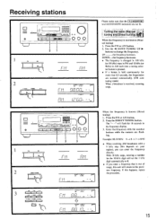
... or AM button. 2. When the frequency is changed in 100 kHz (or 50 kHz) steps in FM and 10 kHz (or 9kHz) in the frequency display. 3. Press the DIRECT TUNING button. With 10 kHz steps, entering a number for the 10 kI-lz digit will return to change the frequency. ual tuning...
... or AM button. 2. When the frequency is changed in 100 kHz (or 50 kHz) steps in FM and 10 kHz (or 9kHz) in the frequency display. 3. Press the DIRECT TUNING button. With 10 kHz steps, entering a number for the 10 kI-lz digit will return to change the frequency. ual tuning...
Owner Manual
Page 16
...It I I I ZI l= rusAVIE & lace 8 wormy 00,0 OTT MAIO . ll I I . time the button is equipped with a PS (Program Service Name), the frequency display will be stored in the memory. 1. Press button 0/10 when choosing memory number 10. NOTErrt If the FM station received is an RDS station with... and 19 for 8 seconds. 3. The STEREO MODE AUTO/MONO settings that you want to store in the memory. (Refer to "Tuning the radio" on the display changes in the following order each group (A, B or C), a total of the signal being received. I Orr 1 00 I 4 a I -- If the signal ...
...It I I I ZI l= rusAVIE & lace 8 wormy 00,0 OTT MAIO . ll I I . time the button is equipped with a PS (Program Service Name), the frequency display will be stored in the memory. 1. Press button 0/10 when choosing memory number 10. NOTErrt If the FM station received is an RDS station with... and 19 for 8 seconds. 3. The STEREO MODE AUTO/MONO settings that you want to store in the memory. (Refer to "Tuning the radio" on the display changes in the following order each group (A, B or C), a total of the signal being received. I Orr 1 00 I 4 a I -- If the signal ...
Owner Manual
Page 17
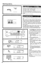
... the GROUP button to receive by pressing the AM or FM input selector button on the main unit or TUNER input selector button on the display. • Once the preset station has been can be received for 5 seconds. or Press the SCAN button. Press the PRESET or P. CAT .. Main unit 1. When...
... the GROUP button to receive by pressing the AM or FM input selector button on the main unit or TUNER input selector button on the display. • Once the preset station has been can be received for 5 seconds. or Press the SCAN button. Press the PRESET or P. CAT .. Main unit 1. When...
Owner Manual
Page 18
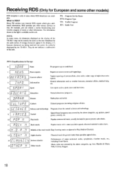
... the natural sciences and technology. . Jazz. What is available on this unit. NOTE: In. If strange characters appear in the display, it is because characters are available. jAdi Middle of the road music Easy listening music as weather forecasts, consumer affairs, medical help... action. SL1. quizzes, panel games, comedy, etc. Receiving RDS (Only for European and some cases, the characters displayed on the display of the TX-8511 may not be correctly displayed by the above categories, eg. II I , un Lr It.t I I ' PI Light classics Serious classics Other...
... the natural sciences and technology. . Jazz. What is available on this unit. NOTE: In. If strange characters appear in the display, it is because characters are available. jAdi Middle of the road music Easy listening music as weather forecasts, consumer affairs, medical help... action. SL1. quizzes, panel games, comedy, etc. Receiving RDS (Only for European and some cases, the characters displayed on the display of the TX-8511 may not be correctly displayed by the above categories, eg. II I , un Lr It.t I I ' PI Light classics Serious classics Other...
Owner Manual
Page 19
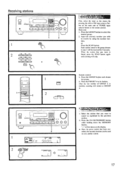
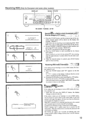
..., the scanning stops for approximately 5 seconds, before the unit starts scanning again. 4. tion cannot be used . 1. if you press the DISPLAY button, the display changes as shown in the left. play. Each time you have entered it can sometimes take between a few seconds and 15 seconds (more ... (avorite category (PTY -*- If the unit cannot receive any signal. When the information is received, the characters will be shown on the display, it indicates that even though an RDS station is being received, there is no characters entered, only the frequency is shown.) When RT ...
..., the scanning stops for approximately 5 seconds, before the unit starts scanning again. 4. tion cannot be used . 1. if you press the DISPLAY button, the display changes as shown in the left. play. Each time you have entered it can sometimes take between a few seconds and 15 seconds (more ... (avorite category (PTY -*- If the unit cannot receive any signal. When the information is received, the characters will be shown on the display, it indicates that even though an RDS station is being received, there is no characters entered, only the frequency is shown.) When RT ...
Owner Manual
Page 20
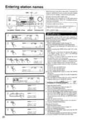
... SMNO button until "O" is not pressed within 16 seconds, the operation will be given the name "ONKYO". If a button is displayed and characters cannot he entered. Select the desired station. (Refer to Selecting preset stations on page 17... saki° 1 I b I I., / Li I 0 % ', 1- 1 I 11 GROUP -1 I . 3 Ll.... _i L_0u, 2 DIAJPETER 0 SPEAKERS A .. . /AA l6A16 r %RED 4 CA. If a button is displayed. Press the -4 DOWN or UP10- TUNING button to move one more time. The frequency in the following sequence: 5 -->M ->N O 5... button. 5.Press the CHARACTER button to enter...
... SMNO button until "O" is not pressed within 16 seconds, the operation will be given the name "ONKYO". If a button is displayed and characters cannot he entered. Select the desired station. (Refer to Selecting preset stations on page 17... saki° 1 I b I I., / Li I 0 % ', 1- 1 I 11 GROUP -1 I . 3 Ll.... _i L_0u, 2 DIAJPETER 0 SPEAKERS A .. . /AA l6A16 r %RED 4 CA. If a button is displayed. Press the -4 DOWN or UP10- TUNING button to move one more time. The frequency in the following sequence: 5 -->M ->N O 5... button. 5.Press the CHARACTER button to enter...
Owner Manual
Page 23
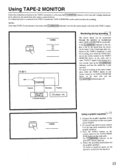
If the T-2 MONITOR indicator in the display is to be used to the tape deck connectors on the main unit and the T-2 MONITOR indicator goes off . TAPES MONITOR B TX-8511 AMP. If the 3-head tape deck connected to the TAPE-2 connectors is just recorded. Connect the graphic equalizer to the ...button on the main unit's display lights up the T-2 MONITOR indicator, and hear the sound that is used , connect it to monitor the recording. To record an equalized signal, use the tape deck connected to the TAPE-2 connectors on the rear panel of the TX-8511. 2. Using TAPE-2 MONITOR ...
If the T-2 MONITOR indicator in the display is to be used to the tape deck connectors on the main unit and the T-2 MONITOR indicator goes off . TAPES MONITOR B TX-8511 AMP. If the 3-head tape deck connected to the TAPE-2 connectors is just recorded. Connect the graphic equalizer to the ...button on the main unit's display lights up the T-2 MONITOR indicator, and hear the sound that is used , connect it to monitor the recording. To record an equalized signal, use the tape deck connected to the TAPE-2 connectors on the rear panel of the TX-8511. 2. Using TAPE-2 MONITOR ...
Owner Manual
Page 24
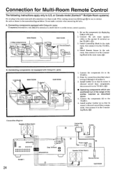
...Remote Sensor\ 2. Install Connecting Block in the main room. Connecting components not equipped with Onkyo R I Speaker A (Main room) \ 7-\ \ TX-8511 7 , Speaker A (Main room) 3. A. Connecting block - \.- \ Power ...TX -8511. 5. Components(b) / \ \ s.-- .r . Connect the components (d) to U.S. Make the connections described above 4. or Canada model (Xantechm' Multiple-Room systems) Do not plug in SPEAKERS B TX-8511 24 Connecting block Emitter U 0 Power supply Lev Speaker B (Sub Room) O Remote Sensor SUB ROOM Set up the components (a) displaying Onkyo...
...Remote Sensor\ 2. Install Connecting Block in the main room. Connecting components not equipped with Onkyo R I Speaker A (Main room) \ 7-\ \ TX-8511 7 , Speaker A (Main room) 3. A. Connecting block - \.- \ Power ...TX -8511. 5. Components(b) / \ \ s.-- .r . Connect the components (d) to U.S. Make the connections described above 4. or Canada model (Xantechm' Multiple-Room systems) Do not plug in SPEAKERS B TX-8511 24 Connecting block Emitter U 0 Power supply Lev Speaker B (Sub Room) O Remote Sensor SUB ROOM Set up the components (a) displaying Onkyo...
Owner Manual
Page 25
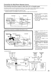
...Sub room) Connection diagram Speaker A Main Room) I jack. 2. then connect it to the TX-851I. (C)) B. Install Remote Emitter Head 11E-10 so that its sensor is directed toward these components. Onkyo components (a) TX-8511 L Speaker A -',/ Speaker A (Main room) / f* (Main room) 7 -\ \`. Remote... ROOM 1. Set up the components (a) displaying Onkyo's R I . A. then connect it to the TX-851I. (®) (Connect the AC adapter to enable remote control operation. then connect it to other than U.S. Components(c) i I \-+- I TX-8511 \ Spearke7 (Main room) 1/ . ...
...Sub room) Connection diagram Speaker A Main Room) I jack. 2. then connect it to the TX-851I. (C)) B. Install Remote Emitter Head 11E-10 so that its sensor is directed toward these components. Onkyo components (a) TX-8511 L Speaker A -',/ Speaker A (Main room) / f* (Main room) 7 -\ \`. Remote... ROOM 1. Set up the components (a) displaying Onkyo's R I . A. then connect it to the TX-851I. (®) (Connect the AC adapter to enable remote control operation. then connect it to other than U.S. Components(c) i I \-+- I TX-8511 \ Spearke7 (Main room) 1/ . ...

