Owner Manual
Page 2
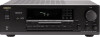
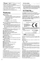
...drive II Costly, high-quality parts such as practical. -• FOR CANADIAN MODEL POUR LE MODELE CANADIEN • For models having a power cord with the coloured markings identifying the terminals in this appliance may not correspond with a polarized plug. Please retain this plug. FOR EUROPEAN ... INSERT. • Sur les modeles dont la fiche est polarisee. A built-in this manual for purchasing Me Onkyo TX-8511 Audio Video Control Rlteiier. YAMAZOE ONKYO EUROPE ELECTRONICS GMBH zmiumi ATTENTION FOR BRITISH MODEL Replacement and mounting of an AC plug on the body of 5 amps...
...drive II Costly, high-quality parts such as practical. -• FOR CANADIAN MODEL POUR LE MODELE CANADIEN • For models having a power cord with the coloured markings identifying the terminals in this appliance may not correspond with a polarized plug. Please retain this plug. FOR EUROPEAN ... INSERT. • Sur les modeles dont la fiche est polarisee. A built-in this manual for purchasing Me Onkyo TX-8511 Audio Video Control Rlteiier. YAMAZOE ONKYO EUROPE ELECTRONICS GMBH zmiumi ATTENTION FOR BRITISH MODEL Replacement and mounting of an AC plug on the body of 5 amps...
Owner Manual
Page 3
...a book case or cabinet that its proper ventilation. for the grounding electrode. excessive force, and uneven surfaces may be adhered to a power supply only of suffi- PORTABLE CART WARNING 53125A 7. S. Ventilation -The appliance should be situated so that may block the ventilation openings...water - Cleaning - Nonuse Periods - Object and Liquid Entry - Damage Requiring Service - The appliance should be moved with arrowhead symbol. The power-supply cord or the plug has been damaged: or B. Objects have fallen. The appliance has been dropped. be sure the antenna system is ...
...a book case or cabinet that its proper ventilation. for the grounding electrode. excessive force, and uneven surfaces may be adhered to a power supply only of suffi- PORTABLE CART WARNING 53125A 7. S. Ventilation -The appliance should be situated so that may block the ventilation openings...water - Cleaning - Nonuse Periods - Object and Liquid Entry - Damage Requiring Service - The appliance should be moved with arrowhead symbol. The power-supply cord or the plug has been damaged: or B. Objects have fallen. The appliance has been dropped. be sure the antenna system is ...
Owner Manual
Page 4
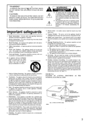
... switehable. 50/60Hz Other: AC 770V, 6011z • Voltage Selector (Rear Panel) Worldwide models are designed for other than personal use only with the power supply voltage of warranty claim, please report this , dry immediately with a soft cloth. OTHER USA / f•t Setting the voZage selector (worldwide model..., insert a screwdriver into the grs)eve in the switch and slide the switch completely to match the voltage of the power supply in your area before plugging in your Onkyo authorized service station. 4. Do not use for your area: 220 - 230 V or 120 V. 2, If .the ...
... switehable. 50/60Hz Other: AC 770V, 6011z • Voltage Selector (Rear Panel) Worldwide models are designed for other than personal use only with the power supply voltage of warranty claim, please report this , dry immediately with a soft cloth. OTHER USA / f•t Setting the voZage selector (worldwide model..., insert a screwdriver into the grs)eve in the switch and slide the switch completely to match the voltage of the power supply in your area before plugging in your Onkyo authorized service station. 4. Do not use for your area: 220 - 230 V or 120 V. 2, If .the ...
Owner Manual
Page 5
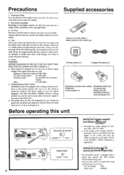
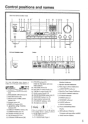
... 6' 7 ONSVi r0 ralat, CORDS /pad .r•Va Ira 4.0. 0•100, MK 0 8 9 10 11 12 13 14 Is PIO u CO i Ttit!) ) 4.1•04.400 TX 5,, 22 21 USA and Canadian model 20 19 18 17 16 15 Display a d e f ah i k I -APRRR STEREO MODE ''•MOOE [ULM MU WIN I . TUNED 4 MEMORY... -2 MO R VIDEO OE ON OFF STEREO ...-GrE m"i2tf1r\1iu-i1l-\t"r?.m\t/I . POWER (or SYSTEM) switch 11 2 1 2. SCAN button [17, 191 12. MEMORY button 1 16, 171 20. FM MUTE ON/OFF indicator h. Preset station/sleep timer display ...
... 6' 7 ONSVi r0 ralat, CORDS /pad .r•Va Ira 4.0. 0•100, MK 0 8 9 10 11 12 13 14 Is PIO u CO i Ttit!) ) 4.1•04.400 TX 5,, 22 21 USA and Canadian model 20 19 18 17 16 15 Display a d e f ah i k I -APRRR STEREO MODE ''•MOOE [ULM MU WIN I . TUNED 4 MEMORY... -2 MO R VIDEO OE ON OFF STEREO ...-GrE m"i2tf1r\1iu-i1l-\t"r?.m\t/I . POWER (or SYSTEM) switch 11 2 1 2. SCAN button [17, 191 12. MEMORY button 1 16, 171 20. FM MUTE ON/OFF indicator h. Preset station/sleep timer display ...
Owner Manual
Page 6
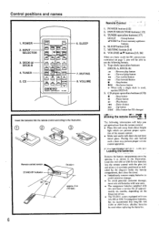
...W1L75n 1=1 A CI CI (= 4se VOLUME C] ONKYO REMOTE CONTROLLER RC-MS 6. VOLUME A/V buttons [13, 26] When you get optimal use the following information will be used , operate DECK-B. 5. iNnirorM?•ffp LwV/,i 4, 4w ?w, • Loading the batteries - CD POWER SLEEP INPUT SELECTOR n :fE nl •... mentioned on page 7, you will help you have tinted glass. O O (-3O Remote control sensor STAND-BY indicator 30' 30* TX-8511 approx. 5 m (16 feet) 6 RernOte'COntrol' ' 1. Load two AA (R6 or UM-3)-size batteries into the remote control...
...W1L75n 1=1 A CI CI (= 4se VOLUME C] ONKYO REMOTE CONTROLLER RC-MS 6. VOLUME A/V buttons [13, 26] When you get optimal use the following information will be used , operate DECK-B. 5. iNnirorM?•ffp LwV/,i 4, 4w ?w, • Loading the batteries - CD POWER SLEEP INPUT SELECTOR n :fE nl •... mentioned on page 7, you will help you have tinted glass. O O (-3O Remote control sensor STAND-BY indicator 30' 30* TX-8511 approx. 5 m (16 feet) 6 RernOte'COntrol' ' 1. Load two AA (R6 or UM-3)-size batteries into the remote control...

Owner Manual
Page 7
....uveolirgnrtoet"e.1c!oI ntrol connections Cassette tape decks and a compact disc player that are equipped with an Onkyo RI connector can be used to the left . To wall outlet CAUTION: Do not plug in the power cord until all connections have been made. .NIENN. [63: ra UO Alle. ROI ..tit ORPROARGE... enable remote control operation of connectors, the connector (red and marked R) corresponds to the right channel and the connector (white and marked L) to control Onkyo turntables. • An R I remote control cable equipped with 1/8" (3.5 mm) mini jacks is included with an R I 1.O.
....uveolirgnrtoet"e.1c!oI ntrol connections Cassette tape decks and a compact disc player that are equipped with an Onkyo RI connector can be used to the left . To wall outlet CAUTION: Do not plug in the power cord until all connections have been made. .NIENN. [63: ra UO Alle. ROI ..tit ORPROARGE... enable remote control operation of connectors, the connector (red and marked R) corresponds to the right channel and the connector (white and marked L) to control Onkyo turntables. • An R I remote control cable equipped with 1/8" (3.5 mm) mini jacks is included with an R I 1.O.
Owner Manual
Page 8
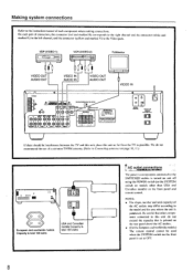
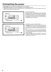
... Capacity is total 100 watts USA and Canadian models Capacity is total 120 watts AC outlet connections The power to components connected to the SWITCHED outlets is turned on and off using the POWER switch (or the SYSTEM switch on models other components connected to this unit do not recommend the use...
... Capacity is total 100 watts USA and Canadian models Capacity is total 120 watts AC outlet connections The power to components connected to the SWITCHED outlets is turned on and off using the POWER switch (or the SYSTEM switch on models other components connected to this unit do not recommend the use...

Owner Manual
Page 9
... illustration, observing the correct con- Close the lever. nections for R, L, + and -. • Do not use unnecessarily long or extremely thin speaker leads. nected in the power cord during speaker system connection and operation of the SPEAKER IMPEDANCE SELECTOR. Making system connections USA and Canadian models to the explanation of "Speaker impedance...
... illustration, observing the correct con- Close the lever. nections for R, L, + and -. • Do not use unnecessarily long or extremely thin speaker leads. nected in the power cord during speaker system connection and operation of the SPEAKER IMPEDANCE SELECTOR. Making system connections USA and Canadian models to the explanation of "Speaker impedance...
Owner Manual
Page 11
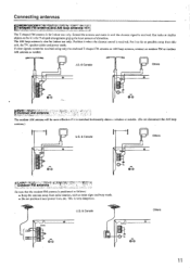
...8226;•t•d•••oL.o.,rr FM antenna n. • Be sure that the outdoor FM antenna is received. Put it near power lines, etc. Extend the antenna and move it until the clearest signal is positioned as follows: • Keep the antenna away from this..., unit, the TV, speaker cables and power cords. J.S. & Canada Others L 0 0 • €® r','O7:ue11t !•3''Oo'r.r.APgrMACt.!a•4r,4it"6t.i'n•%n,',E';' t The outdoor ...
...8226;•t•d•••oL.o.,rr FM antenna n. • Be sure that the outdoor FM antenna is received. Put it near power lines, etc. Extend the antenna and move it until the clearest signal is positioned as follows: • Keep the antenna away from this..., unit, the TV, speaker cables and power cords. J.S. & Canada Others L 0 0 • €® r','O7:ue11t !•3''Oo'r.r.APgrMACt.!a•4r,4it"6t.i'n•%n,',E';' t The outdoor ...
Owner Manual
Page 12
... is lit). If so, use a wall outlet on the TX-851 I . If this unit's power may cause a momentary power surge, which might interfere with other than U.S. The remote control cannot be used to operate the TX-8511 if the SYSTEM switch is used in power-on status (the unit can be sure that the VOLUME... knob is fully turned counterclockwise. • Turning on this switch is lit) and power-on the TX-851 I to set it to OFF turns off the...
... is lit). If so, use a wall outlet on the TX-851 I . If this unit's power may cause a momentary power surge, which might interfere with other than U.S. The remote control cannot be used to operate the TX-8511 if the SYSTEM switch is used in power-on status (the unit can be sure that the VOLUME... knob is fully turned counterclockwise. • Turning on this switch is lit) and power-on the TX-851 I to set it to OFF turns off the...
Owner Manual
Page 13
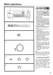
... from the speakers any sound going through this unit's input selector when changing listening sources. 13 The SELECTIVE TONE indicator lights up on the. The power cord should be removed from the speakers. 3. r .tfklit . . If both SPEAKERS (A and B) are connected together, you can use for a.... ble. The BALANCE knob is selected, refer to clearly reproduce ultralow and -high frequencies. NOTE: The power does not shut off . Simply by just turning the power off completely by directly operating the desired component (compact disc player or tape deck), this button to "Receiving...
... from the speakers any sound going through this unit's input selector when changing listening sources. 13 The SELECTIVE TONE indicator lights up on the. The power cord should be removed from the speakers. 3. r .tfklit . . If both SPEAKERS (A and B) are connected together, you can use for a.... ble. The BALANCE knob is selected, refer to clearly reproduce ultralow and -high frequencies. NOTE: The power does not shut off . Simply by just turning the power off completely by directly operating the desired component (compact disc player or tape deck), this button to "Receiving...
Owner Manual
Page 14
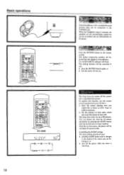
...operate this function, use the remote control supplied with the SPEAKERS A/ B buttons. After the set time passes, the power will be cancelled if you are not automatically muted but can be controlled with your TX-85I I. 1. RC-329S a/ Er c c o LL1 90 80 70 Cancel -4- 10 20 14 Listen n' t... ' Stereo headphones with a standard binaural (stereo) plug can be connected to , or • turn off. You can power off the system after which you would...
...operate this function, use the remote control supplied with the SPEAKERS A/ B buttons. After the set time passes, the power will be cancelled if you are not automatically muted but can be controlled with your TX-85I I. 1. RC-329S a/ Er c c o LL1 90 80 70 Cancel -4- 10 20 14 Listen n' t... ' Stereo headphones with a standard binaural (stereo) plug can be connected to , or • turn off. You can power off the system after which you would...
Owner Manual
Page 24
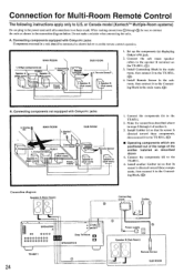
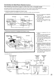
... in the connection diagram below to the TX-8511. (0) 4. Components(d) TX-8511 I Speaker A (Main room) \ 7-\ \ TX-8511 7 , Speaker A (Main room) 3. Components(b) / \ \ s.-- .r . Do not make a mistake when connecting the units. Speaker B (Sub room) 1. Make the connections described above 4. Connecting block - \.- \ Power supply Remote -control 4. Speaker B (Sub room) 7Thr 2. Connecting components not equipped with Onkyo R I jacks Components mounted in the...
... in the connection diagram below to the TX-8511. (0) 4. Components(d) TX-8511 I Speaker A (Main room) \ 7-\ \ TX-8511 7 , Speaker A (Main room) 3. Components(b) / \ \ s.-- .r . Do not make a mistake when connecting the units. Speaker B (Sub room) 1. Make the connections described above 4. Connecting block - \.- \ Power supply Remote -control 4. Speaker B (Sub room) 7Thr 2. Connecting components not equipped with Onkyo R I jacks Components mounted in the...
Owner Manual
Page 25
... sensor HR-10 SUB ROOM 25 SUB ROOM Remote control in3. Install Remote Sensor Ilk -10 in the power cord until all connections have been made. Remote Emitte Head HE-10 SUB ROOM 4. Onkyo components (a) TX-8511 L Speaker A -',/ Speaker A (Main room) / f* (Main room) 7 -\ \`. Speaker B (Sub room) 77\ 2. Install Remote Emitter 11E-50 (AC) so...
... sensor HR-10 SUB ROOM 25 SUB ROOM Remote control in3. Install Remote Sensor Ilk -10 in the power cord until all connections have been made. Remote Emitte Head HE-10 SUB ROOM 4. Onkyo components (a) TX-8511 L Speaker A -',/ Speaker A (Main room) / f* (Main room) 7 -\ \`. Speaker B (Sub room) 77\ 2. Install Remote Emitter 11E-50 (AC) so...
Owner Manual
Page 27
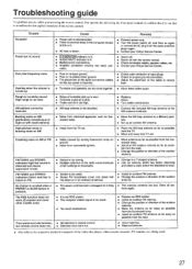
...Connect the included AM loop antenna to the respective instruction manuals of turntable pick-up an outdoor AM antenna. Remedy • Connect power cord. • Turn the power switch off . • Noise from automobile ignition. • Move antenna as far as possible from the fluorescent lamp. &#... on AM (particularly conspicuous at night or with the remote control. • Check connection cables, speaker cables, etc. • Contact your Onkyo Service Center. The RDS function does not work. (European and some other models only) • Station is too strong. • Multiple ...
...Connect the included AM loop antenna to the respective instruction manuals of turntable pick-up an outdoor AM antenna. Remedy • Connect power cord. • Turn the power switch off . • Noise from automobile ignition. • Move antenna as far as possible from the fluorescent lamp. &#... on AM (particularly conspicuous at night or with the remote control. • Check connection cables, speaker cables, etc. • Contact your Onkyo Service Center. The RDS function does not work. (European and some other models only) • Station is too strong. • Multiple ...

Owner Manual
Page 28
... worldwide models: 87.50 to change without notice. N.T., HONG KONG Tel: 852.2429-3118 Fax: 852-2428-9039 ONKYO httpiNJHewOMwE.ePnAkGyEoI.m.fp/ 107960 Specifications AMPLIFIER SECTION Power Output: USA & Canadian models: 100 Watts per channel. Frequency Response: 20 to 30.000 Hz. ±1 dB...Canadian models: AC120 V. 60 Hz European and Australian models: AC230 V. 50 Hz Worldwide models: AC 220-230/120 V switchable, 50/60 Hz Power Consumption: U.S. and Canadian models: '40 dB Other models: 85 dB IF Rejection Ratio: 90 dB Signal-t-oNoise Ratio: Mono: 76 dB, 1HF...
... worldwide models: 87.50 to change without notice. N.T., HONG KONG Tel: 852.2429-3118 Fax: 852-2428-9039 ONKYO httpiNJHewOMwE.ePnAkGyEoI.m.fp/ 107960 Specifications AMPLIFIER SECTION Power Output: USA & Canadian models: 100 Watts per channel. Frequency Response: 20 to 30.000 Hz. ±1 dB...Canadian models: AC120 V. 60 Hz European and Australian models: AC230 V. 50 Hz Worldwide models: AC 220-230/120 V switchable, 50/60 Hz Power Consumption: U.S. and Canadian models: '40 dB Other models: 85 dB IF Rejection Ratio: 90 dB Signal-t-oNoise Ratio: Mono: 76 dB, 1HF...


