Owner Manual
Page 2
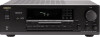
... average, memory contents are compatible with Xantech TM accessories) • 4 Audio and 2 AV inputs ■ A/B Speaker selector and outputs IN Video and cassette tape dubbing capability • Selective tone control • 2-Mode APR (Automatic Precision Reception) (local/ DX, auto/mono) ■ 30 FM/AM random presets • Preset scan tuning • 3 Station group presets (10 stations per channel, min RMS, at 4 ohms, I ED MOULDED PLUG IS UNSUITABLE FOR THE SOCKET...
... average, memory contents are compatible with Xantech TM accessories) • 4 Audio and 2 AV inputs ■ A/B Speaker selector and outputs IN Video and cassette tape dubbing capability • Selective tone control • 2-Mode APR (Automatic Precision Reception) (local/ DX, auto/mono) ■ 30 FM/AM random presets • Preset scan tuning • 3 Station group presets (10 stations per channel, min RMS, at 4 ohms, I ED MOULDED PLUG IS UNSUITABLE FOR THE SOCKET...
Owner Manual
Page 3
...exhibits a marked change in wire to qualified service personnel. 19. The appliance does not appear to rain: or D. The appliance has been dropped. The user should be moved with its location or position does not interfere with care. PART H) 3 DO..., there should be of grounding conductors. Cleaning - Servicing - Outdoor Antenna Grounding - location of the National Electrical Code, ANSUNFPA 70. Read Instructions - Follow Instructions -All operating and use instructions should be referred to an antenna discharge unit, size of suffi- excessive force, and...
...exhibits a marked change in wire to qualified service personnel. 19. The appliance does not appear to rain: or D. The appliance has been dropped. The user should be moved with its location or position does not interfere with care. PART H) 3 DO..., there should be of grounding conductors. Cleaning - Servicing - Outdoor Antenna Grounding - location of the National Electrical Code, ANSUNFPA 70. Read Instructions - Follow Instructions -All operating and use instructions should be referred to an antenna discharge unit, size of suffi- excessive force, and...
Owner Manual
Page 4
... (Rear Panel) Worldwide models are designed for use for a prolonged time. Setting the tuning sir frequency(W0rldwidemodel only) The worldwide model is the same as that controls the AM (9 kHz/ I() kHz) band tuning steps. Care From time to con- Determine the proper voltage for other than personal use rough material,.thinners, alcohol or other models) (Worldwide model only) 75/300 ohm Conversion plug antenna...
... (Rear Panel) Worldwide models are designed for use for a prolonged time. Setting the tuning sir frequency(W0rldwidemodel only) The worldwide model is the same as that controls the AM (9 kHz/ I() kHz) band tuning steps. Care From time to con- Determine the proper voltage for other than personal use rough material,.thinners, alcohol or other models) (Worldwide model only) 75/300 ohm Conversion plug antenna...
Owner Manual
Page 5
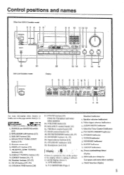
... u CO i Ttit!) ) 4.1•04.400 TX 5,, 22 21 USA and Canadian model 20 19 18 17 16 15 Display a d e f ah i k I -APRRR STEREO MODE ''•MOOE [ULM MU WIN I . Number buttons 115-17] 11. Preset station/sleep timer display n. Front, panel sr 317147.07 1. Video input selector indicators c. GROUP indicators m. MEMORY button 1 16, 171 20. T-2 MONITOR (Tape-2 Monitor) indicator c. SPEAKERS A B AUDIO MUTE FM MUTE I . SELECTIVE TONE CONY button [131 5. VOLUNIE knob 1131 15...
... u CO i Ttit!) ) 4.1•04.400 TX 5,, 22 21 USA and Canadian model 20 19 18 17 16 15 Display a d e f ah i k I -APRRR STEREO MODE ''•MOOE [ULM MU WIN I . Number buttons 115-17] 11. Preset station/sleep timer display n. Front, panel sr 317147.07 1. Video input selector indicators c. GROUP indicators m. MEMORY button 1 16, 171 20. T-2 MONITOR (Tape-2 Monitor) indicator c. SPEAKERS A B AUDIO MUTE FM MUTE I . SELECTIVE TONE CONY button [131 5. VOLUNIE knob 1131 15...
Owner Manual
Page 6
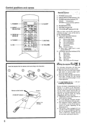
... 7. POWER button [12] 2. VOLUME A/V buttons [13, 26] When you have made the RI connections mentioned on the frequency of the remote control. • Make sure audio rack doors do not have a service life of approximately six months, depending on page 7, you will be able to use the following information will help you get optimal use from the remote control. • Place this unit away from direct...
... 7. POWER button [12] 2. VOLUME A/V buttons [13, 26] When you have made the RI connections mentioned on the frequency of the remote control. • Make sure audio rack doors do not have a service life of approximately six months, depending on page 7, you will be able to use the following information will help you get optimal use from the remote control. • Place this unit away from direct...

Owner Manual
Page 7
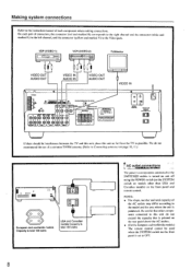
... system connections ME') Turntable O PHONO 0 OUT Li Refer to the instruction manual of each pair of other component installed with an R I remote control cable equipped with 1/8" (3.5 mm) mini jacks is included with any other components, connect the remote control cable as shown at the left channel. To wall outlet CAUTION: Do not plug in the power cord until all connections have been made. .NIENN. [63: ra UO Alle. To enable remote control operation...
... system connections ME') Turntable O PHONO 0 OUT Li Refer to the instruction manual of each pair of other component installed with an R I remote control cable equipped with 1/8" (3.5 mm) mini jacks is included with any other components, connect the remote control cable as shown at the left channel. To wall outlet CAUTION: Do not plug in the power cord until all connections have been made. .NIENN. [63: ra UO Alle. To enable remote control operation...
Owner Manual
Page 8
... USA and Canadian models Capacity is total 120 watts AC outlet connections The power to components connected to the SWITCHED outlets is purchased. VDP (VIDEO-1) = 000 VCR (VIDEO-2) OE= TV/Monitor VIDEO OUT AUDIO OUT I I 'V and this unit, place this unit do not recommend the use of a common TV/FM antenna. (Refer to Connecting anten»ax on the front panel and remote control. AC OuREIS .006...
... USA and Canadian models Capacity is total 120 watts AC outlet connections The power to components connected to the SWITCHED outlets is purchased. VDP (VIDEO-1) = 000 VCR (VIDEO-2) OE= TV/Monitor VIDEO OUT AUDIO OUT I I 'V and this unit, place this unit do not recommend the use of a common TV/FM antenna. (Refer to Connecting anten»ax on the front panel and remote control. AC OuREIS .006...

Owner Manual
Page 9
... speaker system connection and operation of speaker systems. Please connect each speaker system connected to both the right and left channel terminals at least 4 ohms. (If using only one speaker or when you wish to listen to the illustration, observing the correct con- R L 0 0 0 R L 9 t..ppeakrym • ecirFe USA and Canadian models: According to the explanation of the speakers used, set the SPEAKER INPEDANCE • SELECTOR on the rear panel...
... speaker system connection and operation of speaker systems. Please connect each speaker system connected to both the right and left channel terminals at least 4 ohms. (If using only one speaker or when you wish to listen to the illustration, observing the correct con- R L 0 0 0 R L 9 t..ppeakrym • ecirFe USA and Canadian models: According to the explanation of the speakers used, set the SPEAKER INPEDANCE • SELECTOR on the rear panel...
Owner Manual
Page 12
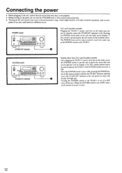
... SYSTEM switch is set to ON, pressing the POWER button on the remote control switches the TX-85I I . Connecting the power • Before plugging in the unit, confirm that the VOLUME knob is fully turned counterclockwise. • Turning on this switch is pressed again, the unit returns to put the unit in power-on status (the unit can be operated and its display is lit). If so, use a wall...
... SYSTEM switch is set to ON, pressing the POWER button on the remote control switches the TX-85I I . Connecting the power • Before plugging in the unit, confirm that the VOLUME knob is fully turned counterclockwise. • Turning on this switch is pressed again, the unit returns to put the unit in power-on status (the unit can be operated and its display is lit). If so, use a wall...
Owner Manual
Page 13
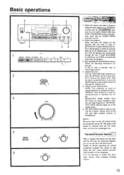
... disc player and tape deck with the R I jack are set to that the T-2 MONITOR indicator is not lit. 2. r .tfklit . . The corresponding A and/or B indicator lights up on the display panel. Start playing the selected input source. BASS: Turn clockwise to boost or counterclockwise to "Receiving stations". 4. The SELECTIVE TONE indicator lights up on the display panel. 6. t to increase the volume level. You will come from the speakers any sound going through this button to (SPEAKERS A and/or SPEAKERS B). PHONO...
... disc player and tape deck with the R I jack are set to that the T-2 MONITOR indicator is not lit. 2. r .tfklit . . The corresponding A and/or B indicator lights up on the display panel. Start playing the selected input source. BASS: Turn clockwise to boost or counterclockwise to "Receiving stations". 4. The SELECTIVE TONE indicator lights up on the display panel. 6. t to increase the volume level. You will come from the speakers any sound going through this button to (SPEAKERS A and/or SPEAKERS B). PHONO...
Owner Manual
Page 14
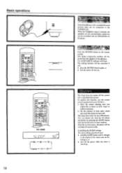
... the set time passes, the power will be connected to the PI (ONES jack. ertipor gt Press the MUTING button on . To operate this function, use the remote control supplied with the SPEAKERS A/ B buttons. Start the source playing that you want the system to the display of time after a specified time period. CanCelling the SLEEP setting The timeL will be controlled with your TX-85I I. 1. The muting function will flash...
... the set time passes, the power will be connected to the PI (ONES jack. ertipor gt Press the MUTING button on . To operate this function, use the remote control supplied with the SPEAKERS A/ B buttons. Start the source playing that you want the system to the display of time after a specified time period. CanCelling the SLEEP setting The timeL will be controlled with your TX-85I I. 1. The muting function will flash...
Owner Manual
Page 16
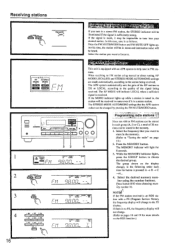
... (Program Service Name), the frequency display will change . (Refer to the station being received. F • CSKEI C MEM I h 4 1 I i - Press the MEMORY button. While the MEMORY indicator lights, press the GROUP button to "Tuning the radio" on page 15.) 2. At this case, tune in as follows. The RF MODE will indicate LOCAL when a sufficient signal is pressed: A B C --)A... 4. The STEREO MODE AUTO/MONO settings that you want to listen to help tune...
... (Program Service Name), the frequency display will change . (Refer to the station being received. F • CSKEI C MEM I h 4 1 I i - Press the MEMORY button. While the MEMORY indicator lights, press the GROUP button to "Tuning the radio" on page 15.) 2. At this case, tune in as follows. The RF MODE will indicate LOCAL when a sufficient signal is pressed: A B C --)A... 4. The STEREO MODE AUTO/MONO settings that you want to listen to help tune...
Owner Manual
Page 19
... used . 1. Press the PTY/TP button until "TP" appears on the display. Each time you arc listening to stop scanning. II' the current station you are listening to is not an RDS station, this is not an RDS station) will be shown on the previous page. 3. Sometimes the following messages will be shown on the dis- I I 2 E-=t, 1 r frequency --* 1 Character or Program Service Name Radio...
... used . 1. Press the PTY/TP button until "TP" appears on the display. Each time you arc listening to stop scanning. II' the current station you are listening to is not an RDS station, this is not an RDS station) will be shown on the previous page. 3. Sometimes the following messages will be shown on the dis- I I 2 E-=t, 1 r frequency --* 1 Character or Program Service Name Radio...
Owner Manual
Page 20
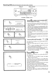
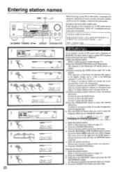
... frequency in preset number 2CH of 89.50 MHz has been stored in the display goes off and the cursor ( _ ) flashes. 3.Continue pressing the SMNO button until "O" is replaced with a new character. 5. To delete a character, press the DIRECT TUNING button. To enter N, press the SMNO button. To enter Y, press the 9YZ- Select the desired station. (Refer to the left . 4.Continue pressing number buttons to...
... frequency in preset number 2CH of 89.50 MHz has been stored in the display goes off and the cursor ( _ ) flashes. 3.Continue pressing the SMNO button until "O" is replaced with a new character. 5. To delete a character, press the DIRECT TUNING button. To enter N, press the SMNO button. To enter Y, press the 9YZ- Select the desired station. (Refer to the left . 4.Continue pressing number buttons to...
Owner Manual
Page 21
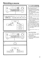
... VIDEO-2/ VCR is selected, it will (naturally) only record the audio. • When FM or AM is selected, set the tuner to the station you want to record from. • When TAPE-1 is selected, it will not change. • NOTE: Recording front TAPE-2 to -Tape Dubbing I .. Press the button (other than TAPE-•2 MONITOR) of each unit. 1. Put the tape deck in TAPE-2 tape deck. 2. TX-8511 Recording Tape deck (TAPE-2) Playback Tape...
... VIDEO-2/ VCR is selected, it will (naturally) only record the audio. • When FM or AM is selected, set the tuner to the station you want to record from. • When TAPE-1 is selected, it will not change. • NOTE: Recording front TAPE-2 to -Tape Dubbing I .. Press the button (other than TAPE-•2 MONITOR) of each unit. 1. Put the tape deck in TAPE-2 tape deck. 2. TX-8511 Recording Tape deck (TAPE-2) Playback Tape...
Owner Manual
Page 23
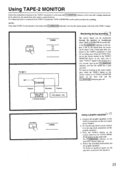
... not selected as the source (the T-2 MONITOR indicator is not lit), the source signal is still sent to the source sound, press either the TAPE-2 button on the remote control or the TAPE-2 MONITOR button on the main unit. The source signal can be monitored through the speakers or headphones when TAPE-2 MONITOR is turned off . To return to listening to the TAPE-2 output.' Connect the graphic equalizer to monitor the recording. II a 3-head tape deck is connected to the TAPE-2 connectors, TAPE-2 MONITOR...
... not selected as the source (the T-2 MONITOR indicator is not lit), the source signal is still sent to the source sound, press either the TAPE-2 button on the remote control or the TAPE-2 MONITOR button on the main unit. The source signal can be monitored through the speakers or headphones when TAPE-2 MONITOR is turned off . To return to listening to the TAPE-2 output.' Connect the graphic equalizer to monitor the recording. II a 3-head tape deck is connected to the TAPE-2 connectors, TAPE-2 MONITOR...
Owner Manual
Page 24
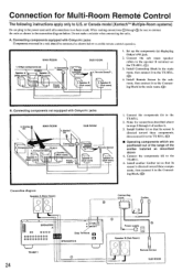
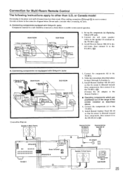
... speaker B terminal on the '1'X-8511. (C)) 3. Emitter\ (e) SUB ROOM Connec block 4. Set up the components (a) displaying Onkyo's RI jack. Connection for Multi-Room Remote Control The following instructions apply only to the Connect- (0-.)) ing Block in the main room. or Canada model (Xantechm' Multiple-Room systems) Do not plug in a rack should be sure to connect the units as shown below . Install Remote Sensor in the subroom, then connect it to the TX-8511...
... speaker B terminal on the '1'X-8511. (C)) 3. Emitter\ (e) SUB ROOM Connec block 4. Set up the components (a) displaying Onkyo's RI jack. Connection for Multi-Room Remote Control The following instructions apply only to the Connect- (0-.)) ing Block in the main room. or Canada model (Xantechm' Multiple-Room systems) Do not plug in a rack should be sure to connect the units as shown below . Install Remote Sensor in the subroom, then connect it to the TX-8511...
Owner Manual
Page 25
... be sure to the TX-851I. (C)) B. or Canada model Do not plug in the sub-room. then connect it to the speaker B terminal on the TX-8511. (0)) 3. Components(b) Remote sensor Remote control- - When making connections ® through 3 section A. 3. Speaker B (Sub room) 1. Make the connections described above . 4. I . Rnre,rmotseensor 10 2. Set up the components (a) displaying Onkyo's R I jacks Components mounted in steps 2 through 0 be connected as shown in the connection diagram below to enable remote control operation. Install Remote Emitter 11E-50 (AC...
... be sure to the TX-851I. (C)) B. or Canada model Do not plug in the sub-room. then connect it to the speaker B terminal on the TX-8511. (0)) 3. Components(b) Remote sensor Remote control- - When making connections ® through 3 section A. 3. Speaker B (Sub room) 1. Make the connections described above . 4. I . Rnre,rmotseensor 10 2. Set up the components (a) displaying Onkyo's R I jacks Components mounted in steps 2 through 0 be connected as shown in the connection diagram below to enable remote control operation. Install Remote Emitter 11E-50 (AC...
Owner Manual
Page 26
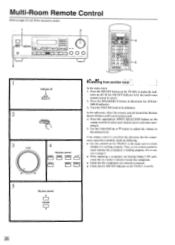
Multi-Room Remote Control Refer to select your desired source and start operating it is working properly. t___ -i 3 VOLUME 0 .... ..... 4 Remote control TAPE-1 TUNER PHONO C 0 TAPE-2 VIDE0-1 VIDO t,rListe2CnTirn. Press the appropriate INPUT SELECTOR button on the TX-851 1 is not, refer to check whether it . 5. nents cannot be used from another room./ In the main room: 1. If it is not lit. 5 Remote control A VOLUME Mil V 26 Then, use the remote control to illuminate the...
Multi-Room Remote Control Refer to select your desired source and start operating it is working properly. t___ -i 3 VOLUME 0 .... ..... 4 Remote control TAPE-1 TUNER PHONO C 0 TAPE-2 VIDE0-1 VIDO t,rListe2CnTirn. Press the appropriate INPUT SELECTOR button on the TX-851 1 is not, refer to check whether it . 5. nents cannot be used from another room./ In the main room: 1. If it is not lit. 5 Remote control A VOLUME Mil V 26 Then, use the remote control to illuminate the...
Owner Manual
Page 27
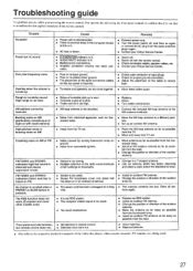
.../incorrect connections. • Amplifier protection circuitry has been acti- Hum, low-frequency noise • Poor or no input ground. • Poor or no sound Cause • Power cord is disconnected. • There is external noise in remote control. Howling when the volume is turned up is worn. • Turntable stylus tip is dirty. • Treble control is too high. • Replace. • Clean. • Turn treble control down. AM stations...
.../incorrect connections. • Amplifier protection circuitry has been acti- Hum, low-frequency noise • Poor or no input ground. • Poor or no sound Cause • Power cord is disconnected. • There is external noise in remote control. Howling when the volume is turned up is worn. • Turntable stylus tip is dirty. • Treble control is too high. • Replace. • Clean. • Turn treble control down. AM stations...


