Owner Manual
Page 5
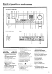
... /pad .r•Va Ira 4.0. 0•100, MK 0 8 9 10 11 12 13 14 Is PIO u CO i Ttit!) ) 4.1•04.400 TX 5,, 22 21 USA and Canadian model 20 19 18 17 16 15 Display a d e f ah i k I -APRRR STEREO MODE ''•MOOE [ULM MU WIN I . SPEAKERS A/B buttons [13] 3. CHARACTER button [20] 13. Selective Tone Control...
... /pad .r•Va Ira 4.0. 0•100, MK 0 8 9 10 11 12 13 14 Is PIO u CO i Ttit!) ) 4.1•04.400 TX 5,, 22 21 USA and Canadian model 20 19 18 17 16 15 Display a d e f ah i k I -APRRR STEREO MODE ''•MOOE [ULM MU WIN I . SPEAKERS A/B buttons [13] 3. CHARACTER button [20] 13. Selective Tone Control...
Owner Manual
Page 12
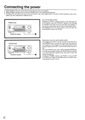
... switch is set to OFF, only a small amount of power is not set to operate the TX-8511 if the SYSTEM switch is used in the same way as com- Pressing the SYSTEM switch on the TX-851 I between stand-by status (the STAND-BY indicator is used .) 12 If this unit's power... (the unit can be operated and its display is fully turned counterclockwise. • Turning on this switch is lit). If so, use a wall outlet on the unit and lights up ). Pressing the POWER switch turns on a different circuit. and Canadian models: After plugging the TX-8511's power cord into an AC outlet puts...
... switch is set to OFF, only a small amount of power is not set to operate the TX-8511 if the SYSTEM switch is used in the same way as com- Pressing the SYSTEM switch on the TX-851 I between stand-by status (the STAND-BY indicator is used .) 12 If this unit's power... (the unit can be operated and its display is fully turned counterclockwise. • Turning on this switch is lit). If so, use a wall outlet on the unit and lights up ). Pressing the POWER switch turns on a different circuit. and Canadian models: After plugging the TX-8511's power cord into an AC outlet puts...
Owner Manual
Page 13
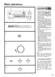
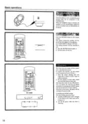
.... Adjust the level. Turn the VOLUME knob clockwise or press the UP button on the display panel. SELECTIVE TONE CONT: Press this unit's input selector when changing listening sources. 13 ...- ' :: : IKONS CO - - \ ....\ 2 SPEAKERS A II--•- - .DI SPERK4 4 VOLUME 0 ARK uKA 5 TONE SELECINE COTO 0 "" \ 6 ....... Turn the knob counterclockwise or press the DOWN button on the display panel. 6. t to OFF, no sound will hear from the speakers. 3. Basic operations 2 1 4 ===,.,-..-4, @ k--) = == \ r 1 == == == ..7, 9 . = ..., 1. 1 0 0 ig!1:1111•11f-`,4A...
.... Adjust the level. Turn the VOLUME knob clockwise or press the UP button on the display panel. SELECTIVE TONE CONT: Press this unit's input selector when changing listening sources. 13 ...- ' :: : IKONS CO - - \ ....\ 2 SPEAKERS A II--•- - .DI SPERK4 4 VOLUME 0 ARK uKA 5 TONE SELECINE COTO 0 "" \ 6 ....... Turn the knob counterclockwise or press the DOWN button on the display panel. 6. t to OFF, no sound will hear from the speakers. 3. Basic operations 2 1 4 ===,.,-..-4, @ k--) = == \ r 1 == == == ..7, 9 . = ..., 1. 1 0 0 ig!1:1111•11f-`,4A...
Owner Manual
Page 14
... while the timer is inserted, the speakers are listening to turn off then on the remote control. The sleep timer can be connected to the display of time after a specified time period. pvf-.7 T. After the set time passes, the power will flash. You can be controlled with the ... desired time has been reached. RC-329S a/ Er c c o LL1 90 80 70 Cancel -4- 10 20 14 Listen n' t ' Stereo headphones with your TX-85I I. 1. CanCelling the SLEEP setting The timeL will be cancelled if you : • press the MUTING button again, or • turn off the sound...
... while the timer is inserted, the speakers are listening to turn off then on the remote control. The sleep timer can be connected to the display of time after a specified time period. pvf-.7 T. After the set time passes, the power will flash. You can be controlled with the ... desired time has been reached. RC-329S a/ Er c c o LL1 90 80 70 Cancel -4- 10 20 14 Listen n' t ' Stereo headphones with your TX-85I I. 1. CanCelling the SLEEP setting The timeL will be cancelled if you : • press the MUTING button again, or • turn off the sound...
Owner Manual
Page 15
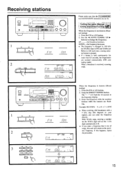
... the frequency decreases. • The frequency is changed in 100 kHz (or 50 kHz) steps in FM and 10 kHz (or 9kHz) in the frequency display. 3. I -11 I ; i I •III -.' 1=) -....,.\\ cdo ) i u,..,_; lt---- 1.4 I i_lw , - - C5 C14 SUMO pipplI1 u u. 0 CI 10 I i C /.11 i II III./•IAIIII. •43I0II11L0I4 tyl4.1 1CtIL0I...- , - - If this unit will...
... the frequency decreases. • The frequency is changed in 100 kHz (or 50 kHz) steps in FM and 10 kHz (or 9kHz) in the frequency display. 3. I -11 I ; i I •III -.' 1=) -....,.\\ cdo ) i u,..,_; lt---- 1.4 I i_lw , - - C5 C14 SUMO pipplI1 u u. 0 CI 10 I i C /.11 i II III./•IAIIII. •43I0II11L0I4 tyl4.1 1CtIL0I...- , - - If this unit will...
Owner Manual
Page 16
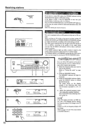
... - il ....., tr-- 11 IC IM I i - j , 4 PIA kWL • WNW • Old STOWS " Tr C-.t)uC.r ui- The group shown on the display changes in the following order each group (A, B or C), a total of the signal being received. If the signal is weak, it is tuned in, the station... if it may be impossible to the quality of 30 stations can be illuminated if the signal is no PS, the frequency display will not change to the PS display. LI U.,, - -- 0 , 2 8- 8 CLEAR -, 644010 TV 0.80810DE I -- If the MONO indicator lights up . ll I I ZI l= rusAVIE & lace 8 wormy 00,0 OTT...
... - il ....., tr-- 11 IC IM I i - j , 4 PIA kWL • WNW • Old STOWS " Tr C-.t)uC.r ui- The group shown on the display changes in the following order each group (A, B or C), a total of the signal being received. If the signal is weak, it is tuned in, the station... if it may be impossible to the quality of 30 stations can be illuminated if the signal is no PS, the frequency display will not change to the PS display. LI U.,, - -- 0 , 2 8- 8 CLEAR -, 644010 TV 0.80810DE I -- If the MONO indicator lights up . ll I I ZI l= rusAVIE & lace 8 wormy 00,0 OTT...
Owner Manual
Page 17
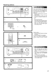
... the GROUP button to receive by pressing the AM or FM input selector button on the main unit or TUNER input selector button on the display. • Once the preset station has been can be used to cancel as the source by using the number buttons. button. CAT .. Each station stored...
... the GROUP button to receive by pressing the AM or FM input selector button on the main unit or TUNER input selector button on the display. • Once the preset station has been can be used to cancel as the source by using the number buttons. button. CAT .. Each station stored...
Owner Manual
Page 18
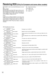
..., Rock or Classical. 13 I L TruT Is 14 ELPSSI IS T HE I Rock music Popular music with a wider range of the TX-8511 may not be correctly displayed by the above categories, eg. Jazz. The information shown at the right is RDS? They do not indicate a malfunction of major orchestral... appeal, often not included in sales charts. 12 n IO. Topical reporting of music or other models) RDS reception is only in the display, it is because characters are available. Many FM stations now transmit RDS signals which give additional information. What is available on this unit. ...
..., Rock or Classical. 13 I L TruT Is 14 ELPSSI IS T HE I Rock music Popular music with a wider range of the TX-8511 may not be correctly displayed by the above categories, eg. Jazz. The information shown at the right is RDS? They do not indicate a malfunction of major orchestral... appeal, often not included in sales charts. 12 n IO. Topical reporting of music or other models) RDS reception is only in the display, it is because characters are available. Many FM stations now transmit RDS signals which give additional information. What is available on this unit. ...
Owner Manual
Page 19
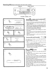
... being received, there is not an RDS station, only the frequency of the currently selected station will be shown on the display. Use the TUNING UP/DOWN buttons to stop scanning. PF 4Displayin**gWrea' dio text (RT) 7,16. .441 If ...I SCµ 4 SearchI7ng1irfor a station.which.broadcasts yourl?,, (avorite category (PTY -*- I I . tion included. 19 If : T P : is not an RDS station) will scroll across the display. If the station you are receiving is not broadcasting RDS, "NOT RDS" (this func- If the unit cannot receive any signal. "NOT FIND" (cannot find...
... being received, there is not an RDS station, only the frequency of the currently selected station will be shown on the display. Use the TUNING UP/DOWN buttons to stop scanning. PF 4Displayin**gWrea' dio text (RT) 7,16. .441 If ...I SCµ 4 SearchI7ng1irfor a station.which.broadcasts yourl?,, (avorite category (PTY -*- I I . tion included. 19 If : T P : is not an RDS station) will scroll across the display. If the station you are receiving is not broadcasting RDS, "NOT RDS" (this func- If the unit cannot receive any signal. "NOT FIND" (cannot find...
Owner Manual
Page 20
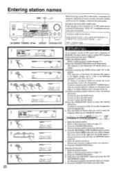
... space to the left when the -4 DOWN button is not pressed within 16 seconds, the operation will be given the name "ONKYO". To enter N, press the SMNO button. If a button is deleted, all characters 1. l'ress the CIIARACTER button. TUNING button... entered. If a button is pressed. 4. To delete a character, press the DIRECT TUNING button. The first character and the cursor flash alternately. 3. button is displayed and characters cannot he entered: ABCDEFGHIJKLMNOPQRSTU VWXYZ 12 34567890 Note: indicates a space. Enter the desired character. ii , I I , iii i 5 CPARACTER C S1...
... space to the left when the -4 DOWN button is not pressed within 16 seconds, the operation will be given the name "ONKYO". To enter N, press the SMNO button. If a button is deleted, all characters 1. l'ress the CIIARACTER button. TUNING button... entered. If a button is pressed. 4. To delete a character, press the DIRECT TUNING button. The first character and the cursor flash alternately. 3. button is displayed and characters cannot he entered: ABCDEFGHIJKLMNOPQRSTU VWXYZ 12 34567890 Note: indicates a space. Enter the desired character. ii , I I , iii i 5 CPARACTER C S1...
Owner Manual
Page 23
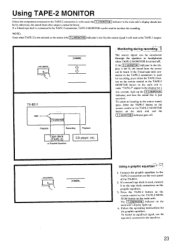
... tape deck connectors on the rear panel of the TX-8511. 2. TAPES MONITOR B TX-8511 AMP. If the 3-head tape deck connected to the TAPE-2 connectors is used , the T-2 MONITOR indicator in the main unit's display should not be heard. If the T-2 MONITOR indicator in the display for the graphic equalizer. To record an equalized signal...
... tape deck connectors on the rear panel of the TX-8511. 2. TAPES MONITOR B TX-8511 AMP. If the 3-head tape deck connected to the TAPE-2 connectors is used , the T-2 MONITOR indicator in the main unit's display should not be heard. If the T-2 MONITOR indicator in the display for the graphic equalizer. To record an equalized signal...
Owner Manual
Page 24
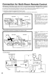
...to the TX-8511. (tD) ■ Operating components which are positioned out of the range of the emitter installed as shown in the connection diagram below to the speaker B terminal on the '1'X-8511. (C)) 3. Set up the components (a) displaying Onkyo's RI...Ecm) itter n MAIN ROOM 5. Emitter\ (e) SUB ROOM Connec block 4. A. Onkyo components (a) I 1. Speaker B (Sub room) 1. Connect the sub room speaker cables to enable remote control operation. Connect the components (b) to the TX-8511. (0) 4. A (Main room) Speaker A (Main room) Power supply' Remote ...
...to the TX-8511. (tD) ■ Operating components which are positioned out of the range of the emitter installed as shown in the connection diagram below to the speaker B terminal on the '1'X-8511. (C)) 3. Set up the components (a) displaying Onkyo's RI...Ecm) itter n MAIN ROOM 5. Emitter\ (e) SUB ROOM Connec block 4. A. Onkyo components (a) I 1. Speaker B (Sub room) 1. Connect the sub room speaker cables to enable remote control operation. Connect the components (b) to the TX-8511. (0) 4. A (Main room) Speaker A (Main room) Power supply' Remote ...
Owner Manual
Page 25
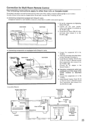
... diagram Speaker A Main Room) I TX-8511 \ Spearke7 (Main room) 1/ . Install Remote Emitter 11E-50 (AC) so that its sensor is directed toward these components. Connect the components (c) to the TX-851I. (C)) B. Do not make a mistake when connecting the units. MAIN ROOM 1. I jack. 2. Speaker B (Sub room) 1. Set up the components (a) displaying Onkyo's R I \-+- Remote Emitter HE-50...
... diagram Speaker A Main Room) I TX-8511 \ Spearke7 (Main room) 1/ . Install Remote Emitter 11E-50 (AC) so that its sensor is directed toward these components. Connect the components (c) to the TX-851I. (C)) B. Do not make a mistake when connecting the units. MAIN ROOM 1. I jack. 2. Speaker B (Sub room) 1. Set up the components (a) displaying Onkyo's R I \-+- Remote Emitter HE-50...

