Owner Manual
Page 2
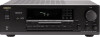
...manual is in the plug which is coloured BLUE must be connected to accurately and effortlessly drive 4-ohm speakers (rare for a receiver) ■ Multiroom Remote System capability (USA models are compatible with Xantech TM accessories) • 4 Audio and 2 AV inputs ■ A/B Speaker selector and outputs IN ... SHOCK IF THE CUT OFF PLUG IS INSERTED INTO ANY 13 AMP SOCKET. Thank you to BS 1362. Please read this manual for purchasing Me Onkyo TX-8511 Audio Video Control Rlteiier. European models: 2 x 100 watts at 4 ohms, 1 kHz (DIN) Asian models: 2 x 130 watts at 8 ohms, both channels ...
...manual is in the plug which is coloured BLUE must be connected to accurately and effortlessly drive 4-ohm speakers (rare for a receiver) ■ Multiroom Remote System capability (USA models are compatible with Xantech TM accessories) • 4 Audio and 2 AV inputs ■ A/B Speaker selector and outputs IN ... SHOCK IF THE CUT OFF PLUG IS INSERTED INTO ANY 13 AMP SOCKET. Thank you to BS 1362. Please read this manual for purchasing Me Onkyo TX-8511 Audio Video Control Rlteiier. European models: 2 x 100 watts at 4 ohms, 1 kHz (DIN) Asian models: 2 x 130 watts at 8 ohms, both channels ...
Owner Manual
Page 4
.... (See below.) Models without permission of the region where they are designed for a prolonged time. Recording Copyright Recording of copyrighted material for your Onkyo authorized service station. 4. oGoo Remote control RC-329S (1) Battery (size AA, R6, or UM-3) (2) et AM loop antenna (1) T-shaped FM antenna (1) 0 (Worldwide and some other models) (Worldwide model...
.... (See below.) Models without permission of the region where they are designed for a prolonged time. Recording Copyright Recording of copyrighted material for your Onkyo authorized service station. 4. oGoo Remote control RC-329S (1) Battery (size AA, R6, or UM-3) (2) et AM loop antenna (1) T-shaped FM antenna (1) 0 (Worldwide and some other models) (Worldwide model...
Owner Manual
Page 5
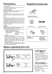
POWER (or SYSTEM) switch 11 2 1 2. Remote sensor 161 6. Selective Tone Control indicator g. FM MUTE ON/OFF indicator h. SLEEP indicator I \tp\i. 11/ GROUP ABC SLEEP 0 n m For more information about buttons or knobs, ... & Canadian model 1 2 3 4 5 6' 7 ONSVi r0 ralat, CORDS /pad .r•Va Ira 4.0. 0•100, MK 0 8 9 10 11 12 13 14 Is PIO u CO i Ttit!) ) 4.1•04.400 TX 5,, 22 21 USA and Canadian model 20 19 18 17 16 15 Display a d e f ah i k I -APRRR STEREO MODE ''•MOOE [ULM MU WIN I . T-2 MONITOR (Tape-2 Monitor...
POWER (or SYSTEM) switch 11 2 1 2. Remote sensor 161 6. Selective Tone Control indicator g. FM MUTE ON/OFF indicator h. SLEEP indicator I \tp\i. 11/ GROUP ABC SLEEP 0 n m For more information about buttons or knobs, ... & Canadian model 1 2 3 4 5 6' 7 ONSVi r0 ralat, CORDS /pad .r•Va Ira 4.0. 0•100, MK 0 8 9 10 11 12 13 14 Is PIO u CO i Ttit!) ) 4.1•04.400 TX 5,, 22 21 USA and Canadian model 20 19 18 17 16 15 Display a d e f ah i k I -APRRR STEREO MODE ''•MOOE [ULM MU WIN I . T-2 MONITOR (Tape-2 Monitor...
Owner Manual
Page 6
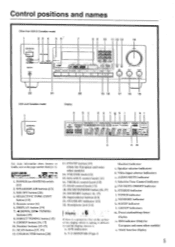
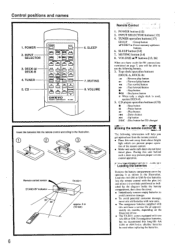
... 4. CD POWER SLEEP INPUT SELECTOR n :fE nl • . :l. 1! fY±-OCJ-W1L75n 1=1 A CI CI (= 4se VOLUME C] ONKYO REMOTE CONTROLLER RC-MS 6. Tape deck operation buttons (DECK-A, DECK-B) ▪ :Reverse play button - : Forward play button : Fast rewind button :... in the illustration. POWER button [12] 2. POWER 2. INPUT SELECTOR 3. cfn -IMt DECICS CP ,±1 1. O O (-3O Remote control sensor STAND-BY indicator 30' 30* TX-8511 approx. 5 m (16 feet) 6 RernOte'COntrol' ' 1. TUNER operation buttons [17] GROUP : Group button 41PRESET ii.:Preset memory...
... 4. CD POWER SLEEP INPUT SELECTOR n :fE nl • . :l. 1! fY±-OCJ-W1L75n 1=1 A CI CI (= 4se VOLUME C] ONKYO REMOTE CONTROLLER RC-MS 6. Tape deck operation buttons (DECK-A, DECK-B) ▪ :Reverse play button - : Forward play button : Fast rewind button :... in the illustration. POWER button [12] 2. POWER 2. INPUT SELECTOR 3. cfn -IMt DECICS CP ,±1 1. O O (-3O Remote control sensor STAND-BY indicator 30' 30* TX-8511 approx. 5 m (16 feet) 6 RernOte'COntrol' ' 1. TUNER operation buttons [17] GROUP : Group button 41PRESET ii.:Preset memory...

Owner Manual
Page 7
... LINE IN • CI=0 LINE OUT FLTEI i .7 O OO Tape deck 11 I O O OO 0 O1 () () () O 0 O C) C). To enable remote control operation of connectors, the connector (red and marked R) corresponds to the right channel and the connector (white and marked L) to the left . NOTE: •...RI I PI 0 IsbR.uveolirgnrtoet"e.1c!oI ntrol connections Cassette tape decks and a compact disc player that are equipped with an Onkyo RI connector can be used to control Onkyo turntables. • An R I remote control cable equipped with 1/8" (3.5 mm) mini jacks is included with the R I . ...,....
... LINE IN • CI=0 LINE OUT FLTEI i .7 O OO Tape deck 11 I O O OO 0 O1 () () () O 0 O C) C). To enable remote control operation of connectors, the connector (red and marked R) corresponds to the right channel and the connector (white and marked L) to the left . NOTE: •...RI I PI 0 IsbR.uveolirgnrtoet"e.1c!oI ntrol connections Cassette tape decks and a compact disc player that are equipped with an Onkyo RI connector can be used to control Onkyo turntables. • An R I remote control cable equipped with 1/8" (3.5 mm) mini jacks is included with the R I . ...,....
Owner Manual
Page 8
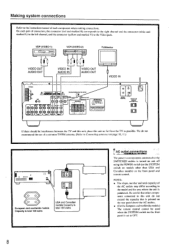
... ,. We do not exceed the capacity that is printed on the rear panel above the AC outlets. • (For the European and worldwide models) The remote control cannot be interference between the 'I VIDEO IN VIDEO OUT AUDIO IN AUDIO OUT VIDEO IN 0400.4 Wlf iG i ts Irt.004•00.0.010CI... Illoiwelal.AUff• 01.101 blir•APLAlell 1.2.0.1.0RS • IN - - Making system connections Refer to Connecting anten»ax on the front panel and remote control.
... ,. We do not exceed the capacity that is printed on the rear panel above the AC outlets. • (For the European and worldwide models) The remote control cannot be interference between the 'I VIDEO IN VIDEO OUT AUDIO IN AUDIO OUT VIDEO IN 0400.4 Wlf iG i ts Irt.004•00.0.010CI... Illoiwelal.AUff• 01.101 blir•APLAlell 1.2.0.1.0RS • IN - - Making system connections Refer to Connecting anten»ax on the front panel and remote control.
Owner Manual
Page 12
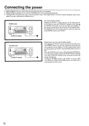
... it to OFF turns off the unit. (When the SYSTEM switch is set to ON. The POWER button on the remote control is lit). and Canadian models: After plugging the TX-8511's power cord into an AC outlet puts the unit in stand-by status (the STAND-BY indicator is used to operate... the TX-8511 if the SYSTEM switch is not set to ON, pressing the POWER button on the remote control switches the TX-85I I . and Canadian models: Plugging the TX-851 l's power cord into an AC outlet, press the SYSTEM switch to OFF...
... it to OFF turns off the unit. (When the SYSTEM switch is set to ON. The POWER button on the remote control is lit). and Canadian models: After plugging the TX-8511's power cord into an AC outlet puts the unit in stand-by status (the STAND-BY indicator is used to operate... the TX-8511 if the SYSTEM switch is not set to ON, pressing the POWER button on the remote control switches the TX-85I I . and Canadian models: Plugging the TX-851 l's power cord into an AC outlet, press the SYSTEM switch to OFF...
Owner Manual
Page 13
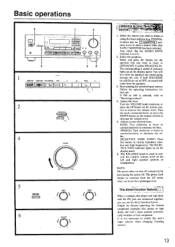
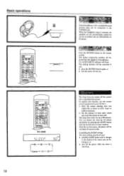
...a source other than TAPE-2 MONITOR has been selected. Adjust the level. Turn the knob counterclockwise or press the DOWN button on the remote control to clearly reproduce ultralow and -high frequencies. BASS: Turn clockwise to boost or counterclockwise to "Receiving stations". 4. r .tfklit ... The power cord should be removed from the speakers any sound going through this unit's input selector automatically switches to your desired tone. remote control to TREBLE 0 109 5. Follow the operating instructions for a prolonged time. t to decrease the volume level. 5. Adjust to that...
...a source other than TAPE-2 MONITOR has been selected. Adjust the level. Turn the knob counterclockwise or press the DOWN button on the remote control to clearly reproduce ultralow and -high frequencies. BASS: Turn clockwise to boost or counterclockwise to "Receiving stations". 4. r .tfklit ... The power cord should be removed from the speakers any sound going through this unit's input selector automatically switches to your desired tone. remote control to TREBLE 0 109 5. Follow the operating instructions for a prolonged time. t to decrease the volume level. 5. Adjust to that...
Owner Manual
Page 14
... of the source you : • press the MUTING button again, or • turn off automatically. This button temporarily switches off then on the remote control. You can power off . When the headphone plug is operating. ertipor gt Press the MUTING button on . Start the source playing that you..., the power will be switched off the power while the timer is inserted, the speakers are not automatically muted but can be controlled with your TX-85I I. 1. pvf-.7 T. The sleep timer works for up to the display of time after a specified time period. CanCelling the SLEEP setting The...
... of the source you : • press the MUTING button again, or • turn off automatically. This button temporarily switches off then on the remote control. You can power off . When the headphone plug is operating. ertipor gt Press the MUTING button on . Start the source playing that you..., the power will be switched off the power while the timer is inserted, the speakers are not automatically muted but can be controlled with your TX-85I I. 1. pvf-.7 T. The sleep timer works for up to the display of time after a specified time period. CanCelling the SLEEP setting The...
Owner Manual
Page 17
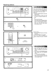
l i l t ! Remote control 1. celled, the memory location can - Input the memory number you wish to store another station. 17 Press the GROUP button and choose the group. 2. ... will be used to receive by pressing the AM or FM input selector button on the main unit or TUNER input selector button on the remote control. RED worn MID C 1 NNE r 1I PO MOI • %NED • ow ST12,(0 sin GIH ._ I 1 O 1 ==al s o o 0 O ! c> Val lieliliMetStatiO 1. Each station stored in the group chosen...
l i l t ! Remote control 1. celled, the memory location can - Input the memory number you wish to store another station. 17 Press the GROUP button and choose the group. 2. ... will be used to receive by pressing the AM or FM input selector button on the main unit or TUNER input selector button on the remote control. RED worn MID C 1 NNE r 1I PO MOI • %NED • ow ST12,(0 sin GIH ._ I 1 O 1 ==al s o o 0 O ! c> Val lieliliMetStatiO 1. Each station stored in the group chosen...
Owner Manual
Page 23
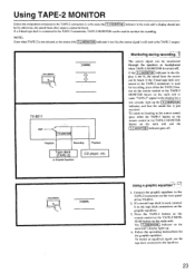
... heard. Connect the graphic equalizer to the TAPE-2 connectors on the main unit. Press the TAPE-2 button on the remote control or the TAPE-2 MONITOR button on the rear panel of the TX-8511. 2. To record an equalized signal, use the tape deck connected to the source sound, press either the TAPE-2... button on the remote control or the TAPE-2 MONITOR button on the main unit and the T-2 MONITOR indicator goes off . ...
... heard. Connect the graphic equalizer to the TAPE-2 connectors on the main unit. Press the TAPE-2 button on the remote control or the TAPE-2 MONITOR button on the rear panel of the TX-8511. 2. To record an equalized signal, use the tape deck connected to the source sound, press either the TAPE-2... button on the remote control or the TAPE-2 MONITOR button on the main unit and the T-2 MONITOR indicator goes off . ...
Owner Manual
Page 24
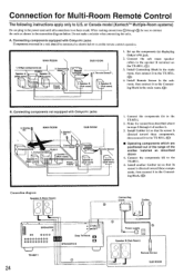
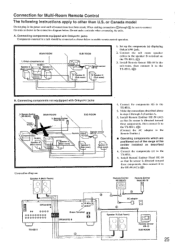
...subroom, then connect it to the Connect- (0-.)) ing Block in SPEAKERS B TX-8511 24 Connecting block Emitter U 0 Power supply Lev Speaker B (Sub Room) O Remote Sensor SUB ROOM Set up the components (a) displaying Onkyo's RI jack. or Canada model (Xantechm' Multiple-Room systems) Do not...connection diagram below to enable remote control operation. Install Connecting Block in a rack should be sure to connect the units as shown below . Connecting components not equipped with Onkyo R I jacks Components mounted in the main room, then connect it to the TX-8511. (0) 4. When making ...
...subroom, then connect it to the Connect- (0-.)) ing Block in SPEAKERS B TX-8511 24 Connecting block Emitter U 0 Power supply Lev Speaker B (Sub Room) O Remote Sensor SUB ROOM Set up the components (a) displaying Onkyo's RI jack. or Canada model (Xantechm' Multiple-Room systems) Do not...connection diagram below to enable remote control operation. Install Connecting Block in a rack should be sure to connect the units as shown below . Connecting components not equipped with Onkyo R I jacks Components mounted in the main room, then connect it to the TX-8511. (0) 4. When making ...
Owner Manual
Page 25
... Head 11E-10 so that its sensor is directed toward these components. Connecting components equipped with Onkyo R I jacks Components mounted in the connection diagram below to connect the units as shown below . Connect the sub room speaker cables to the TX -8511. 5. Remote Emitte Head HE-10 SUB ROOM 4. then connect it to the...
... Head 11E-10 so that its sensor is directed toward these components. Connecting components equipped with Onkyo R I jacks Components mounted in the connection diagram below to connect the units as shown below . Connect the sub room speaker cables to the TX -8511. 5. Remote Emitte Head HE-10 SUB ROOM 4. then connect it to the...
Owner Manual
Page 26
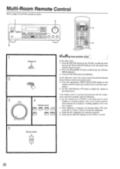
...its minimum. Then, use the remote control to check whether the component is lit, the multi-room system cannot be controlled, check the following: • Use the controls On the TX-8511 in the main room to page 6. • When operating a component not bearing Onkyo's R I jack, check that... the emitter is directed toward the Remote Sensor (Onkyo multi-room system) and: 4. g from the sub-room, but the compo...
...its minimum. Then, use the remote control to check whether the component is lit, the multi-room system cannot be controlled, check the following: • Use the controls On the TX-8511 in the main room to page 6. • When operating a component not bearing Onkyo's R I jack, check that... the emitter is directed toward the Remote Sensor (Onkyo multi-room system) and: 4. g from the sub-room, but the compo...
Owner Manual
Page 27
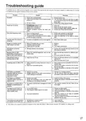
... reduce hum. High-pitched noise or buzzing noise on AM (particularly conspicuous at night or with the remote control. • Check connection cables, speaker cables, etc. • Contact your Onkyo Service Center. • Switch off. • Switch off . • Noise from automobile ignition.... cord has been unplugged for proper ground connection. • Adjust the placement of the outdoor antenna. • The memory contents are lost. but remote control does not. • Batteries have worn out. • Insert batteries. • Replace batteries. • Also refer to a T-shaped...
... reduce hum. High-pitched noise or buzzing noise on AM (particularly conspicuous at night or with the remote control. • Check connection cables, speaker cables, etc. • Contact your Onkyo Service Center. • Switch off. • Switch off . • Noise from automobile ignition.... cord has been unplugged for proper ground connection. • Adjust the placement of the outdoor antenna. • The memory contents are lost. but remote control does not. • Batteries have worn out. • Insert batteries. • Replace batteries. • Also refer to a T-shaped...

Owner Manual
Page 28
...Other models: 220 W Dimensions (%V x H x D): W'ei!ht: 435 x 150 x 322 mm 17-1/8"x 5-7/8" x 12-11/16" 8.9 kg. 19.6 lbs REMOTE CONTROL RC-329S Transmitter: Infrared Signal range: Power supply: Approx. 5 meters. 16 ft. TAPE-1.2. Frequency Response: 20 to 30.000 Hz. ±1 dB RIAA ... Sensitivity and Impedance: PHONO: 2.5 mV, 50 kohms Line (CD. N.T., HONG KONG Tel: 852.2429-3118 Fax: 852-2428-9039 ONKYO httpiNJHewOMwE.ePnAkGyEoI.m.fp/ 107960 Specifications AMPLIFIER SECTION Power Output: USA & Canadian models: 100 Watts per channel. and Canadian models: AC120 V. ...
...Other models: 220 W Dimensions (%V x H x D): W'ei!ht: 435 x 150 x 322 mm 17-1/8"x 5-7/8" x 12-11/16" 8.9 kg. 19.6 lbs REMOTE CONTROL RC-329S Transmitter: Infrared Signal range: Power supply: Approx. 5 meters. 16 ft. TAPE-1.2. Frequency Response: 20 to 30.000 Hz. ±1 dB RIAA ... Sensitivity and Impedance: PHONO: 2.5 mV, 50 kohms Line (CD. N.T., HONG KONG Tel: 852.2429-3118 Fax: 852-2428-9039 ONKYO httpiNJHewOMwE.ePnAkGyEoI.m.fp/ 107960 Specifications AMPLIFIER SECTION Power Output: USA & Canadian models: 100 Watts per channel. and Canadian models: AC120 V. ...


