Owner Manual
Page 2
... presets (10 stations per channel, min RMS, at 4 ohms, I kHz (EIAJ) ■ Discrete output stage circuits for purchasing Me Onkyo TX-8511 Audio Video Control Rlteiier. Please retain this manual thoroughlSriletore making connections and operating the unit. MODEL Note to CATV system installer: • This...RED. Memory Preservation This unit does not require memory preservation batteries. This period is shorter when the unit is in memory power back-up system. On the average, memory contents are coloured in accordance with the following code: Blue: Neutral Brown: Live...
... presets (10 stations per channel, min RMS, at 4 ohms, I kHz (EIAJ) ■ Discrete output stage circuits for purchasing Me Onkyo TX-8511 Audio Video Control Rlteiier. Please retain this manual thoroughlSriletore making connections and operating the unit. MODEL Note to CATV system installer: • This...RED. Memory Preservation This unit does not require memory preservation batteries. This period is shorter when the unit is in memory power back-up system. On the average, memory contents are coloured in accordance with the following code: Blue: Neutral Brown: Live...
Owner Manual
Page 3
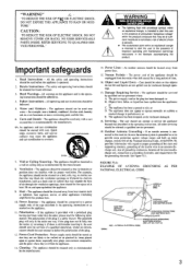
...through openings. 17. If there is connected to defeat the polarization of time. 16. Under no circumstances should be referred to . 4. Power Lines - An outdoor antenna should be retained for a long period of the plug. 12. Objects have fallen. The appliance has been dropped... OF ELECTRIC SHOCK DO NOT OPEN A • The lightning flash with a polarized plug having one way. Read Instructions - Heed Warnings - Power Sources - Damage Requiring Service - The appliance should be situated so that may cause the appliance and cart combination to an antenna discharge unit, ...
...through openings. 17. If there is connected to defeat the polarization of time. 16. Under no circumstances should be referred to . 4. Power Lines - An outdoor antenna should be retained for a long period of the plug. 12. Objects have fallen. The appliance has been dropped... OF ELECTRIC SHOCK DO NOT OPEN A • The lightning flash with a polarized plug having one way. Read Instructions - Heed Warnings - Power Sources - Damage Requiring Service - The appliance should be situated so that may cause the appliance and cart combination to an antenna discharge unit, ...
Owner Manual
Page 4
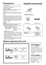
... 230 V), whichever is the same as that controls the AM (9 kHz/ I . Recording Copyright Recording of the copyright holder. 3. If power does not come on the rear panel. Determine the proper voltage for your area before plugging in the unit. (See below.) Models without ... (Worldwide model only) 75/300 ohm Conversion plug antenna adaptor (1) (Shape may vary according to local power supplies. For heavier dirt, dampen a soft cloth in your Onkyo authorized service station. 4. Setting the tuning sir frequency(W0rldwidemodel only) The worldwide model is not correct, ...
... 230 V), whichever is the same as that controls the AM (9 kHz/ I . Recording Copyright Recording of the copyright holder. 3. If power does not come on the rear panel. Determine the proper voltage for your area before plugging in the unit. (See below.) Models without ... (Worldwide model only) 75/300 ohm Conversion plug antenna adaptor (1) (Shape may vary according to local power supplies. For heavier dirt, dampen a soft cloth in your Onkyo authorized service station. 4. Setting the tuning sir frequency(W0rldwidemodel only) The worldwide model is not correct, ...
Owner Manual
Page 5
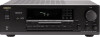
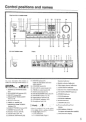
... on the surface of the display which is making it difficult to the page number listedin [ ]. Selective Tone Control indicator g. FM MUTE ON/OFF indicator h. POWER (or SYSTEM) switch 11 2 1 2. DISPLAY button [191 7. 44 DOWN, UP IP- TUNED 4 MEMORY -2 MO R VIDEO OE ON OFF STEREO ... 6' 7 ONSVi r0 ralat, CORDS /pad .r•Va Ira 4.0. 0•100, MK 0 8 9 10 11 12 13 14 Is PIO u CO i Ttit!) ) 4.1•04.400 TX 5,, 22 21 USA and Canadian model 20 19 18 17 16 15 Display a d e f ah i k I -APRRR STEREO MODE ''•MOOE [ULM MU WIN I . Speaker selector ...
... on the surface of the display which is making it difficult to the page number listedin [ ]. Selective Tone Control indicator g. FM MUTE ON/OFF indicator h. POWER (or SYSTEM) switch 11 2 1 2. DISPLAY button [191 7. 44 DOWN, UP IP- TUNED 4 MEMORY -2 MO R VIDEO OE ON OFF STEREO ... 6' 7 ONSVi r0 ralat, CORDS /pad .r•Va Ira 4.0. 0•100, MK 0 8 9 10 11 12 13 14 Is PIO u CO i Ttit!) ) 4.1•04.400 TX 5,, 22 21 USA and Canadian model 20 19 18 17 16 15 Display a d e f ah i k I -APRRR STEREO MODE ''•MOOE [ULM MU WIN I . Speaker selector ...
Owner Manual
Page 6
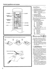
... deck is used when replacing the batteries. O O (-3O Remote control sensor STAND-BY indicator 30' 30* TX-8511 approx. 5 m (16 feet) 6 RernOte'COntrol' ' 1. INI'UT SELECTOR buttons [13] 4. MUTING button... The manganese batteries supplied with this unit have tinted glass. POWER 2. cfn -IMt DECICS CP ,±1 1. SLEEP 7. POWER button [12] 2. VOLUME A/V buttons [13, 26] ... DECK A/ DECK-B 4. TUNER 5. fY±-OCJ-W1L75n 1=1 A CI CI (= 4se VOLUME C] ONKYO REMOTE CONTROLLER RC-MS 6. CI) player operation buttons (CD) • : Stop button II : Pause...
... deck is used when replacing the batteries. O O (-3O Remote control sensor STAND-BY indicator 30' 30* TX-8511 approx. 5 m (16 feet) 6 RernOte'COntrol' ' 1. INI'UT SELECTOR buttons [13] 4. MUTING button... The manganese batteries supplied with this unit have tinted glass. POWER 2. cfn -IMt DECICS CP ,±1 1. SLEEP 7. POWER button [12] 2. VOLUME A/V buttons [13, 26] ... DECK A/ DECK-B 4. TUNER 5. fY±-OCJ-W1L75n 1=1 A CI CI (= 4se VOLUME C] ONKYO REMOTE CONTROLLER RC-MS 6. CI) player operation buttons (CD) • : Stop button II : Pause...

Owner Manual
Page 7
...' RI I PI 0 IsbR.uveolirgnrtoet"e.1c!oI ntrol connections Cassette tape decks and a compact disc player that are equipped with an Onkyo RI connector can be used to control Onkyo turntables. • An R I remote control cable equipped with 1/8" (3.5 mm) mini jacks is included with any other components, ... the remote control included with the fTTg'.: mark. sow O OOO IPLA I . ...,.... To wall outlet CAUTION: Do not plug in the power cord until all connections have been made. .NIENN. [63: ra UO Alle. ROI ..tit ORPROARGE RELlCION SOURER! • R- • orexvo. ...
...' RI I PI 0 IsbR.uveolirgnrtoet"e.1c!oI ntrol connections Cassette tape decks and a compact disc player that are equipped with an Onkyo RI connector can be used to control Onkyo turntables. • An R I remote control cable equipped with 1/8" (3.5 mm) mini jacks is included with any other components, ... the remote control included with the fTTg'.: mark. sow O OOO IPLA I . ...,.... To wall outlet CAUTION: Do not plug in the power cord until all connections have been made. .NIENN. [63: ra UO Alle. ROI ..tit ORPROARGE RELlCION SOURER! • R- • orexvo. ...
Owner Manual
Page 8
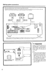
... Capacity is total 100 watts USA and Canadian models Capacity is total 120 watts AC outlet connections The power to components connected to the SWITCHED outlets is turned on and off using the POWER switch (or the SYSTEM switch on the front panel is purchased. VDP (VIDEO-1) = 000 VCR (VIDEO-2) OE= TV...
... Capacity is total 100 watts USA and Canadian models Capacity is total 120 watts AC outlet connections The power to components connected to the SWITCHED outlets is turned on and off using the POWER switch (or the SYSTEM switch on the front panel is purchased. VDP (VIDEO-1) = 000 VCR (VIDEO-2) OE= TV...

Owner Manual
Page 9
... leads is too high, the damping factor will decrease, adversely affecting the sound quality. • When using only A or only B, 4 ohms min.; nected in the power cord during speaker system connection and operation of speaker systems. Please connect each speaker system connected to monaural (mono), the single speaker should never be...
... leads is too high, the damping factor will decrease, adversely affecting the sound quality. • When using only A or only B, 4 ohms min.; nected in the power cord during speaker system connection and operation of speaker systems. Please connect each speaker system connected to monaural (mono), the single speaker should never be...
Owner Manual
Page 11
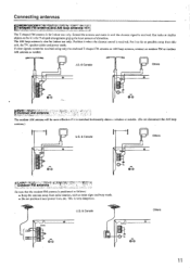
... Others ay 6"e 11 The AM loop antenna is positioned as follows: • Keep the antenna away from this, unit, the TV, speaker cables and power cords. This is received. Use tacks or similar objects to lix it until the clearest signal is for indoor use only. tnewnrnraAiTaIn'md•,rA... antenna as neon signs and busy roads. • Do not position it where the clearest sound is very dangerous. Position it near power lines, etc. Put it as far as possible away from noise sources, such as needed. Connecting antennas r T4tehrraopmetVdtFroM•r•t-ar•-fnF-...
... Others ay 6"e 11 The AM loop antenna is positioned as follows: • Keep the antenna away from this, unit, the TV, speaker cables and power cords. This is received. Use tacks or similar objects to lix it until the clearest signal is for indoor use only. tnewnrnraAiTaIn'md•,rA... antenna as neon signs and busy roads. • Do not position it where the clearest sound is very dangerous. Position it near power lines, etc. Put it as far as possible away from noise sources, such as needed. Connecting antennas r T4tehrraopmetVdtFroM•r•t-ar•-fnF-...
Owner Manual
Page 12
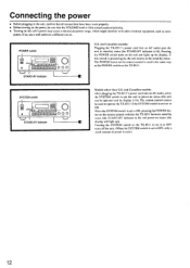
.... (When the SYSTEM switch is set to OFF, only a small amount of power is used.) 12 and Canadian models: Plugging the TX-851 l's power cord into an AC outlet, press the SYSTEM switch to ON. and Canadian models: After plugging the TX-8511's power cord into an AC outlet puts the unit in stand-by status...
.... (When the SYSTEM switch is set to OFF, only a small amount of power is used.) 12 and Canadian models: Plugging the TX-851 l's power cord into an AC outlet, press the SYSTEM switch to ON. and Canadian models: After plugging the TX-8511's power cord into an AC outlet puts the unit in stand-by status...
Owner Manual
Page 13
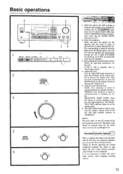
... AUDIO 'MUTE indicator is selected, refer to "Receiving stations". 4. The corresponding A and/or B indicator lights up on the display panel. ble. NOTE: The power does not shut off . It is not lit when a source other than TAPE-2 MONITOR has been selected. r .tfklit . . Select the source you want ...that you wish to listen to attenuate the bass. Follow the operating instructions for a prolonged time. SELECTIVE TONE CONT: Press this unit. The power cord should be removed from the AC outlet when not in use the direct function feature. The BALANCE knob is used to (SPEAKERS A ...
... AUDIO 'MUTE indicator is selected, refer to "Receiving stations". 4. The corresponding A and/or B indicator lights up on the display panel. ble. NOTE: The power does not shut off . It is not lit when a source other than TAPE-2 MONITOR has been selected. r .tfklit . . Select the source you want ...that you wish to listen to attenuate the bass. Follow the operating instructions for a prolonged time. SELECTIVE TONE CONT: Press this unit. The power cord should be removed from the AC outlet when not in use the direct function feature. The BALANCE knob is used to (SPEAKERS A ...
Owner Manual
Page 14
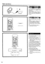
... be cancelled if you are listening to 90 minutes. pvf-.7 T. The sleep timer works for up to , or • turn the power off . When the headphone plug is operating. ertipor gt Press the MUTING button on . This button temporarily switches off the... power while the timer is inserted, the speakers are not automatically muted but can power off automatically. Basic operations n ON1CY0 4K- RC-329S a/ Er c c o LL1 90 80 70 Cancel -4- ...
... be cancelled if you are listening to 90 minutes. pvf-.7 T. The sleep timer works for up to , or • turn the power off . When the headphone plug is operating. ertipor gt Press the MUTING button on . This button temporarily switches off the... power while the timer is inserted, the speakers are not automatically muted but can power off automatically. Basic operations n ON1CY0 4K- RC-329S a/ Er c c o LL1 90 80 70 Cancel -4- ...
Owner Manual
Page 24
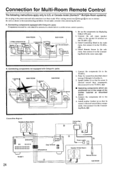
...\ 2. Speaker B (Sub room) 7Thr 2. Connecting components not equipped with Onkyo R I jacks Components mounted in the connection diagram below to the Connecting Block. (C)) Connection diagram Speaker A (Main Room) 0 0 0 0 L • SPEAKERS A 0000 000000000 000000000 MRx IN Gray Terminal in SPEAKERS B TX-8511 24 Connecting block Emitter U 0 Power supply Lev Speaker B (Sub Room) O Remote Sensor SUB ROOM...
...\ 2. Speaker B (Sub room) 7Thr 2. Connecting components not equipped with Onkyo R I jacks Components mounted in the connection diagram below to the Connecting Block. (C)) Connection diagram Speaker A (Main Room) 0 0 0 0 L • SPEAKERS A 0000 000000000 000000000 MRx IN Gray Terminal in SPEAKERS B TX-8511 24 Connecting block Emitter U 0 Power supply Lev Speaker B (Sub Room) O Remote Sensor SUB ROOM...
Owner Manual
Page 25
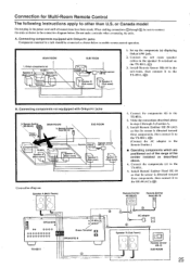
...I jacks 3. Install Remote Sensor Ilk -10 in the power cord until all connections have been made. then connect it to the TX-851I. (®) (Connect the AC adapter to the speaker B terminal on the TX-8511. (0)) 3. Onkyo components (a) TX-8511 L Speaker A -',/ Speaker A (Main room) / f*...O O O O O O O OOOO0 0 OOO MRx IN Green Terminal SPEAKERS B TX-8511 AD,:• =O:3 AC adapter Speaker B (Sub Room) FM) Remote sensor HR-10 SUB ROOM 25 Connecting components not equippped with Onkyo R I TX-8511 \ Spearke7 (Main room) 1/ . Components(c) i I jacks Components mounted in steps ...
...I jacks 3. Install Remote Sensor Ilk -10 in the power cord until all connections have been made. then connect it to the TX-851I. (®) (Connect the AC adapter to the speaker B terminal on the TX-8511. (0)) 3. Onkyo components (a) TX-8511 L Speaker A -',/ Speaker A (Main room) / f*...O O O O O O O OOOO0 0 OOO MRx IN Green Terminal SPEAKERS B TX-8511 AD,:• =O:3 AC adapter Speaker B (Sub Room) FM) Remote sensor HR-10 SUB ROOM 25 Connecting components not equippped with Onkyo R I TX-8511 \ Spearke7 (Main room) 1/ . Components(c) i I jacks Components mounted in steps ...
Owner Manual
Page 27
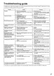
.... • Turn the power switch off, and then on AM (particularly conspicuous at night or with the remote control. • Check connection cables, speaker cables, etc. • Contact your Onkyo Service Center. Howling when the volume is turned up is worn. • Turntable stylus tip is ...dirty. • Treble control is too weak. • Stereo FM broadcasts cover only about hall the distance of an ordinary broadcast, • The power cord has been ...
.... • Turn the power switch off, and then on AM (particularly conspicuous at night or with the remote control. • Check connection cables, speaker cables, etc. • Contact your Onkyo Service Center. Howling when the volume is turned up is worn. • Turntable stylus tip is ...dirty. • Treble control is too weak. • Stereo FM broadcasts cover only about hall the distance of an ordinary broadcast, • The power cord has been ...

Owner Manual
Page 28
...-849-320 Fax: 089-849-3265 E-mail: info@onkyo.de ONKYO CHINA LIMITED Units 2102-2107, Metroplaza Tower I watt output Damping Factor: 60 at 10,000 Hz Signal to 1.602 kHz (9 kHz steps) 30µV 40 dB 40 dB 40 dB 0.7% GENERAL Power Supply: U.S. Kwai Chung. N.T., HONG KONG Tel: 852....2429-3118 Fax: 852-2428-9039 ONKYO httpiNJHewOMwE.ePnAkGyEoI.m.fp/ 107960 VIDEO-1.2): 150 mV, 50 kohms Video (VIDEO-1. 2): Vp-p. 75 ohms Output Level and...
...-849-320 Fax: 089-849-3265 E-mail: info@onkyo.de ONKYO CHINA LIMITED Units 2102-2107, Metroplaza Tower I watt output Damping Factor: 60 at 10,000 Hz Signal to 1.602 kHz (9 kHz steps) 30µV 40 dB 40 dB 40 dB 0.7% GENERAL Power Supply: U.S. Kwai Chung. N.T., HONG KONG Tel: 852....2429-3118 Fax: 852-2428-9039 ONKYO httpiNJHewOMwE.ePnAkGyEoI.m.fp/ 107960 VIDEO-1.2): 150 mV, 50 kohms Video (VIDEO-1. 2): Vp-p. 75 ohms Output Level and...


