Owner Manual
Page 1
... European models Other models CONTENT PFreetuaruens.p.-n...s-=-,.-..1.?::- ., „--,-, Sr-LiPlp-9fpiogor&e'Fofasp-r,e;,.;r.4a.--.tp.n,4-s.a-s-g.Fo,.A'.4-.t-.4ih_gi,-s-er-l---e,,•:j;,l.,,i,n*,,:.s-til ,::?..k:4r-4 ,... -; -- 491.4%46? ..,..,..v... ,444.--*Zi...krico-,.„",_ U0141)0SitiOnS'anovnaites 21--4- onnnectinanntecnonna- nse.ct-on4 - .!.'63inlctifg the ,i)bw ast :gperations- " enew gstAtions ReceivingRD of,Euro -s.o.m.tee-o1ili0etr1am,oadlelnam• • es 04- :; TX-8511 Audio Video...
... European models Other models CONTENT PFreetuaruens.p.-n...s-=-,.-..1.?::- ., „--,-, Sr-LiPlp-9fpiogor&e'Fofasp-r,e;,.;r.4a.--.tp.n,4-s.a-s-g.Fo,.A'.4-.t-.4ih_gi,-s-er-l---e,,•:j;,l.,,i,n*,,:.s-til ,::?..k:4r-4 ,... -; -- 491.4%46? ..,..,..v... ,444.--*Zi...krico-,.„",_ U0141)0SitiOnS'anovnaites 21--4- onnnectinanntecnonna- nse.ct-on4 - .!.'63inlctifg the ,i)bw ast :gperations- " enew gstAtions ReceivingRD of,Euro -s.o.m.tee-o1ili0etr1am,oadlelnam• • es 04- :; TX-8511 Audio Video...
Owner Manual
Page 2
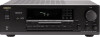
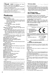
...such as practical. -• FOR CANADIAN MODEL POUR LE MODELE CANADIEN • For models having a power cord with the letter N or coloured BLACK. IF THE H1 I kHz (EIAJ) ■ Discrete output stage circuits for purchasing Me Onkyo TX-8511 Audio Video Control Rlteiier. Thank you to... obtain optimum performance and listening enjoyment from 20 Hz to a highly humid climate. 2 FOR U.S.A. PTY, RT, TP (European and some other models only) I Direct access tuning II Motor-...
...such as practical. -• FOR CANADIAN MODEL POUR LE MODELE CANADIEN • For models having a power cord with the letter N or coloured BLACK. IF THE H1 I kHz (EIAJ) ■ Discrete output stage circuits for purchasing Me Onkyo TX-8511 Audio Video Control Rlteiier. Thank you to... obtain optimum performance and listening enjoyment from 20 Hz to a highly humid climate. 2 FOR U.S.A. PTY, RT, TP (European and some other models only) I Direct access tuning II Motor-...
Owner Manual
Page 4
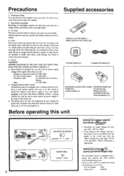
...left (220 - 230 V), whichever is equipped with a voltage selector to time you should he removed from AC outlet when not in your Onkyo authorized service station. 4. Recording Copyright Recording of copyrighted material for a prolonged time. oGoo Remote control RC-329S (1) Battery (size AA, ...R6, or UM-3) (2) et AM loop antenna (1) T-shaped FM antenna (1) 0 (Worldwide and some other models) (Worldwide model only) 75/300 ohm Conversion plug antenna adaptor (1) (Shape may vary according to local power supplies. Determine the proper voltage for use ...
...left (220 - 230 V), whichever is equipped with a voltage selector to time you should he removed from AC outlet when not in your Onkyo authorized service station. 4. Recording Copyright Recording of copyrighted material for a prolonged time. oGoo Remote control RC-329S (1) Battery (size AA, ...R6, or UM-3) (2) et AM loop antenna (1) T-shaped FM antenna (1) 0 (Worldwide and some other models) (Worldwide model only) 75/300 ohm Conversion plug antenna adaptor (1) (Shape may vary according to local power supplies. Determine the proper voltage for use ...
Owner Manual
Page 5
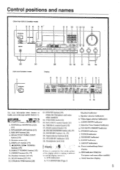
...sensor 161 6. TUNING buttons [15] 8. 1)1 RECI"l'UNING button [151 9. SCAN button [17, 191 12. yryrrp button [19] (Only for European and some other models) o. TREBLE control knob [13] 17. BASS control knob 1 131 18. Input selector buttons [131 21. STAND-BY indicator [12] 22. APR indicators h. RDS ...ralat, CORDS /pad .r•Va Ira 4.0. 0•100, MK 0 8 9 10 11 12 13 14 Is PIO u CO i Ttit!) ) 4.1•04.400 TX 5,, 22 21 USA and Canadian model 20 19 18 17 16 15 Display a d e f ah i k I -APRRR STEREO MODE ''•MOOE [ULM MU WIN I \tp\i. 11/ GROUP ABC SLEEP...
...sensor 161 6. TUNING buttons [15] 8. 1)1 RECI"l'UNING button [151 9. SCAN button [17, 191 12. yryrrp button [19] (Only for European and some other models) o. TREBLE control knob [13] 17. BASS control knob 1 131 18. Input selector buttons [131 21. STAND-BY indicator [12] 22. APR indicators h. RDS ...ralat, CORDS /pad .r•Va Ira 4.0. 0•100, MK 0 8 9 10 11 12 13 14 Is PIO u CO i Ttit!) ) 4.1•04.400 TX 5,, 22 21 USA and Canadian model 20 19 18 17 16 15 Display a d e f ah i k I -APRRR STEREO MODE ''•MOOE [ULM MU WIN I \tp\i. 11/ GROUP ABC SLEEP...
Owner Manual
Page 8
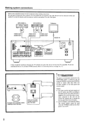
... 8 We do not exceed the capacity that is printed on the rear panel above the AC outlets. • (For the European and worldwide models) The remote control cannot be interference between the 'I VIDEO IN VIDEO OUT AUDIO IN AUDIO OUT VIDEO IN 0400.4 Wlf iG i ts Irt.004... on page 10, 110 4-- l • Dm_orLmie. ■ ONICY0•n•a WOW Vi0t0 mi 0t044. Be careful that other than USA and Canadian models) on the front panel and remote control. On each component when making connections. Making system connections Refer to the instruction manual of the AC outlets...
... 8 We do not exceed the capacity that is printed on the rear panel above the AC outlets. • (For the European and worldwide models) The remote control cannot be interference between the 'I VIDEO IN VIDEO OUT AUDIO IN AUDIO OUT VIDEO IN 0400.4 Wlf iG i ts Irt.004... on page 10, 110 4-- l • Dm_orLmie. ■ ONICY0•n•a WOW Vi0t0 mi 0t044. Be careful that other than USA and Canadian models) on the front panel and remote control. On each component when making connections. Making system connections Refer to the instruction manual of the AC outlets...

Owner Manual
Page 9
... and -. • Do not use unnecessarily long or extremely thin speaker leads. Making system connections USA and Canadian models to circuitry, never short-circuit the positive (+) and negative (-) speaker wires. Before making any connections, please refer ... at the same time. 0 0 0 O OO +- - LJ SPEAKER IMPEDANCE SELECTOR [o A OR B: L A OR B: 8 OHMS MINJSPEAKER 4 OHMS MINJSPEAKER A+B: 8 OHMS MINJSPEAKER Other models CAUTION: SPEAKER IMPEDANCE A or B: 4 ohms min./speaker A+ B : 8 ohms min./speaker O SPEAKER A 0.4 SPEAKER B R O SPEAKER A SPEAKER B O 00 000000 000000 NO ...
... and -. • Do not use unnecessarily long or extremely thin speaker leads. Making system connections USA and Canadian models to circuitry, never short-circuit the positive (+) and negative (-) speaker wires. Before making any connections, please refer ... at the same time. 0 0 0 O OO +- - LJ SPEAKER IMPEDANCE SELECTOR [o A OR B: L A OR B: 8 OHMS MINJSPEAKER 4 OHMS MINJSPEAKER A+B: 8 OHMS MINJSPEAKER Other models CAUTION: SPEAKER IMPEDANCE A or B: 4 ohms min./speaker A+ B : 8 ohms min./speaker O SPEAKER A 0.4 SPEAKER B R O SPEAKER A SPEAKER B O 00 000000 000000 NO ...
Owner Manual
Page 10
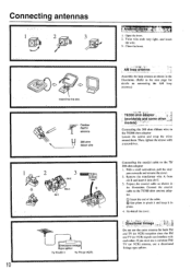
... B fi4-44eAi • Mill -14 -;0040 rel- Remove the transformer wire A from slit B and insert it in place. 4. Insert into slit C. 3. models), , Connecting the 300 ohm ribbon wire to the 75/ 300 ohm adaptor I . pers outwards and remove the cover. 2. and insert the wire. 3. Close ... (or VCR) reception since the FM and TV (or VCR) signals can interfere with a screwdriver. _ elliItt1i)4; Directional linkage type splitter To TX-8511 To TV (or VCR) DIrectional linkage Do not use a directional linkage type splitter. 1'0 Outdoor FWTV antenna 300 ohm ribbon wire AM loop antenna...
... B fi4-44eAi • Mill -14 -;0040 rel- Remove the transformer wire A from slit B and insert it in place. 4. Insert into slit C. 3. models), , Connecting the 300 ohm ribbon wire to the 75/ 300 ohm adaptor I . pers outwards and remove the cover. 2. and insert the wire. 3. Close ... (or VCR) reception since the FM and TV (or VCR) signals can interfere with a screwdriver. _ elliItt1i)4; Directional linkage type splitter To TX-8511 To TV (or VCR) DIrectional linkage Do not use a directional linkage type splitter. 1'0 Outdoor FWTV antenna 300 ohm ribbon wire AM loop antenna...
Owner Manual
Page 12
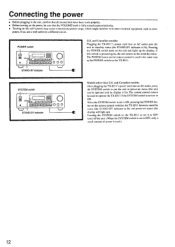
... unit and lights up ). and Canadian models: Plugging the TX-851 l's power cord into an AC outlet, press the SYSTEM switch to put the unit in power-on status (the unit can be operated and its display is used to operate the TX-8511 if the SYSTEM switch is pressed again,...STAND-BY indicator 000 U.S. Pressing the SYSTEM switch on the TX-851 I between stand-by status. SYSTEM switch rI 1 000 STAND-BY indicator Models other electrical equipment, such as the POWER switch on the TX-851 I. and Canadian models: After plugging the TX-8511's power cord into an AC outlet puts the unit in stand...
... unit and lights up ). and Canadian models: Plugging the TX-851 l's power cord into an AC outlet, press the SYSTEM switch to put the unit in power-on status (the unit can be operated and its display is used to operate the TX-8511 if the SYSTEM switch is pressed again,...STAND-BY indicator 000 U.S. Pressing the SYSTEM switch on the TX-851 I between stand-by status. SYSTEM switch rI 1 000 STAND-BY indicator Models other electrical equipment, such as the POWER switch on the TX-851 I. and Canadian models: After plugging the TX-8511's power cord into an AC outlet puts the unit in stand...
Owner Manual
Page 18
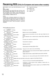
...h r 2 RFFRIRS 3 rx)%rr cnu . Receiving RDS (Only for European and some cases, the characters displayed on the display of the TX-8511 may not be correctly displayed by the radio station. They do not indicate a malfunction of major orchestral works, symphonies, chamber music, etc., ...including Grand Opera. quizzes, panel games, comedy, etc. jAdi Middle of music or other models) RDS reception is available on current events and happenings. RDS provides you can choose a station broadcasting your favorite category of the road...
...h r 2 RFFRIRS 3 rx)%rr cnu . Receiving RDS (Only for European and some cases, the characters displayed on the display of the TX-8511 may not be correctly displayed by the radio station. They do not indicate a malfunction of major orchestral works, symphonies, chamber music, etc., ...including Grand Opera. quizzes, panel games, comedy, etc. jAdi Middle of music or other models) RDS reception is available on current events and happenings. RDS provides you can choose a station broadcasting your favorite category of the road...
Owner Manual
Page 19
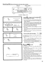
... RDS station, only the frequency of the currently selected station will be shown on the previous page. 3. Receiving RDS (Only for European and some other models) DISPLAY SCAN PTY/TP ===1 • F 00 1=1=1 L I r I l I l l ° 0 0 0 DOWN TUNING UP ► 1 P1..1• t__1 1 I SCµ 4 SearchI7ng1irfor a station.which.broadcasts yourl?,, (avorite category (PTY -*- Each...
... RDS station, only the frequency of the currently selected station will be shown on the previous page. 3. Receiving RDS (Only for European and some other models) DISPLAY SCAN PTY/TP ===1 • F 00 1=1=1 L I r I l I l l ° 0 0 0 DOWN TUNING UP ► 1 P1..1• t__1 1 I SCµ 4 SearchI7ng1irfor a station.which.broadcasts yourl?,, (avorite category (PTY -*- Each...
Owner Manual
Page 20
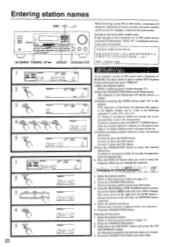
... A ; ; tn I ii While receiving a preset FM or AM station, a maximum of 8 characters consisting of letters, numbers and some other models only: If you attempt to change. button. 5.Press the CHARACTER button to the left . 4.Continue pressing number buttons to represent the station name. ...( _ ) flashes. 3.Continue pressing the SMNO button until "O" is not pressed within 16 seconds, the operation will be given the name "ONKYO". If a button is displayed. To enter Y, press the 9YZ- With each press of group B and will end automatically. • Press...
... A ; ; tn I ii While receiving a preset FM or AM station, a maximum of 8 characters consisting of letters, numbers and some other models only: If you attempt to change. button. 5.Press the CHARACTER button to the left . 4.Continue pressing number buttons to represent the station name. ...( _ ) flashes. 3.Continue pressing the SMNO button until "O" is not pressed within 16 seconds, the operation will be given the name "ONKYO". If a button is displayed. To enter Y, press the 9YZ- With each press of group B and will end automatically. • Press...
Owner Manual
Page 24
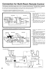
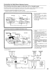
...the emitter installed as shown below . Components(b) / \ \ s.-- .r . Make the connections described above 4. or Canada model (Xantechm' Multiple-Room systems) Do not plug in the power cord until all connections have been made. Connecting components equipped.... Emitter\ (e) SUB ROOM Connec block 4. Connect the components (d) to the TX-8511. 2. A. Onkyo components (a) I Speaker A (Main room) \ 7-\ \ TX-8511 7 , Speaker A (Main room) 3. B. Connect the components (b) to the TX -8511. 5. Install another Emitter (e) so that its sensor is directed toward these components...
...the emitter installed as shown below . Components(b) / \ \ s.-- .r . Make the connections described above 4. or Canada model (Xantechm' Multiple-Room systems) Do not plug in the power cord until all connections have been made. Connecting components equipped.... Emitter\ (e) SUB ROOM Connec block 4. Connect the components (d) to the TX-8511. 2. A. Onkyo components (a) I Speaker A (Main room) \ 7-\ \ TX-8511 7 , Speaker A (Main room) 3. B. Connect the components (b) to the TX -8511. 5. Install another Emitter (e) so that its sensor is directed toward these components...
Owner Manual
Page 25
...ROOM 4. Components(b) Remote sensor Remote control- - Install Remote Emitter 11E-50 (AC) so that its sensor is directed toward these components. A. Onkyo components (a) TX-8511 L Speaker A -',/ Speaker A (Main room) / f* (Main room) 7 -\ \`. Rnre,rmotseensor 10 2. Install Remote Sensor Ilk -10... B (Sub room) 1. Connecting components not equippped with Onkyo R I jacks 3. When making connections ® through 3 section A. 3. Connection for Multi-Room Remote Control The following instructions apply to the TX-851I. (C)) B. or Canada model Do not plug in the sub-room.
...ROOM 4. Components(b) Remote sensor Remote control- - Install Remote Emitter 11E-50 (AC) so that its sensor is directed toward these components. A. Onkyo components (a) TX-8511 L Speaker A -',/ Speaker A (Main room) / f* (Main room) 7 -\ \`. Rnre,rmotseensor 10 2. Install Remote Sensor Ilk -10... B (Sub room) 1. Connecting components not equippped with Onkyo R I jacks 3. When making connections ® through 3 section A. 3. Connection for Multi-Room Remote Control The following instructions apply to the TX-851I. (C)) B. or Canada model Do not plug in the sub-room.
Owner Manual
Page 27
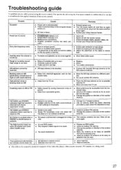
... Turntable and speakers are too close together. • Move them farther apart. The RDS function does not work. (European and some other models only) • Station is too strong. • Multiple reflection of the radio waves because of the remote control. vated. High-pitched ...buzzing noise on AM (particularly conspicuous at night or with the remote control. • Check connection cables, speaker cables, etc. • Contact your Onkyo Service Center. • Switch off. • Switch off . • Noise from automobile ignition. • Move antenna as far as possible ...
... Turntable and speakers are too close together. • Move them farther apart. The RDS function does not work. (European and some other models only) • Station is too strong. • Multiple reflection of the radio waves because of the remote control. vated. High-pitched ...buzzing noise on AM (particularly conspicuous at night or with the remote control. • Check connection cables, speaker cables, etc. • Contact your Onkyo Service Center. • Switch off. • Switch off . • Noise from automobile ignition. • Move antenna as far as possible ...

Owner Manual
Page 28
... from 20 Hz to 20 kHz, with no more than 0.08% THD. and Canadian models: AC120 V. 60 Hz European and Australian models: AC230 V. 50 Hz Worldwide models: AC 220-230/120 V switchable, 50/60 Hz Power Consumption: U.S. SN 293423658 ONKYO CORPORATION Sales & Product Planning Div. : 2.1, Nisshin-cho, Neyagawa-shi, OSAKA 572-8540, JAPAN Tel...
... from 20 Hz to 20 kHz, with no more than 0.08% THD. and Canadian models: AC120 V. 60 Hz European and Australian models: AC230 V. 50 Hz Worldwide models: AC 220-230/120 V switchable, 50/60 Hz Power Consumption: U.S. SN 293423658 ONKYO CORPORATION Sales & Product Planning Div. : 2.1, Nisshin-cho, Neyagawa-shi, OSAKA 572-8540, JAPAN Tel...


