Instruction Manual
Page 3
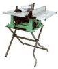
... with Extension ......... 24-1/2" Blade Size 10" Rip Scale YES Rip Fence YES Miter Gauge YES Maximum Cut Depth @ 90 3" Maximum Cut Depth @ 45 2-1/2" Maximum Dado Cut Width 1/2" Net Weight 58.3 LBS WARNING To avoid electrical hazards, fire hazards or damage to the table saw , it is wired at the factory... Right Rip Capacity with approved safety equipment, such as dust masks that you read and understand these rules could result in any way. This table saw is worn, cut or damaged in serious injury to you do this type of California) to a 110-120 Volt / 15 Ampere time delay...
... with Extension ......... 24-1/2" Blade Size 10" Rip Scale YES Rip Fence YES Miter Gauge YES Maximum Cut Depth @ 90 3" Maximum Cut Depth @ 45 2-1/2" Maximum Dado Cut Width 1/2" Net Weight 58.3 LBS WARNING To avoid electrical hazards, fire hazards or damage to the table saw , it is wired at the factory... Right Rip Capacity with approved safety equipment, such as dust masks that you read and understand these rules could result in any way. This table saw is worn, cut or damaged in serious injury to you do this type of California) to a 110-120 Volt / 15 Ampere time delay...
Instruction Manual
Page 4
... they break. 14. Consult the Operator's Manual for most efficient and safest performance. English POWER TOOL SAFETY WARNING Before using your table saw . Failure to you are a combination of flammable liquids or gases. 6. LEARN the tool's applications, limitations and possible hazards. 2....Everyday glasses have read and understand these rules could occur if the tool is tipped or if the cutting tool is not designed. 10. NEVER LEAVE TOOL RUNNING UNATTENDED. Keep proper footing and balance at a safe distance from certain materials can throw debris into the ...
... they break. 14. Consult the Operator's Manual for most efficient and safest performance. English POWER TOOL SAFETY WARNING Before using your table saw . Failure to you are a combination of flammable liquids or gases. 6. LEARN the tool's applications, limitations and possible hazards. 2....Everyday glasses have read and understand these rules could occur if the tool is tipped or if the cutting tool is not designed. 10. NEVER LEAVE TOOL RUNNING UNATTENDED. Keep proper footing and balance at a safe distance from certain materials can throw debris into the ...
Instruction Manual
Page 5
... NEVER CUT METALS or materials that is included on page 24. 4. NEVER ATTEMPT TO FREE A STALLED SAW BLADE without first turning the saw blade. 15. Refer to a complete stop. 10. NEVER USE SOLVENTS to the dust port for long or wide workpieces. 13. Solvents could cause your ...fence as a cut-off gauge when crosscutting. 11. NEVER STAND or have a straight edge to clean plastic parts. 16. English TABLE SAW SAFETY 1. ALWAYS USE SAW BLADE GUARD, splitter and anti-kickback pawls for making your hand to provide sawdust fall-through the workpiece when ripping or crosscutting. ...
... NEVER CUT METALS or materials that is included on page 24. 4. NEVER ATTEMPT TO FREE A STALLED SAW BLADE without first turning the saw blade. 15. Refer to a complete stop. 10. NEVER USE SOLVENTS to the dust port for long or wide workpieces. 13. Solvents could cause your ...fence as a cut-off gauge when crosscutting. 11. NEVER STAND or have a straight edge to clean plastic parts. 16. English TABLE SAW SAFETY 1. ALWAYS USE SAW BLADE GUARD, splitter and anti-kickback pawls for making your hand to provide sawdust fall-through the workpiece when ripping or crosscutting. ...
Instruction Manual
Page 6
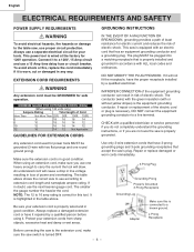
English ELECTRICAL REQUIREMENTS AND SAFETY POWER SUPPLY REQUIREMENTS WARNING To avoid electrical hazards, fire hazards or damage to the table saw, use a separate electrical circuit for your tools. Always use proper circuit protection. EXTENSION CORD REQUIREMENTS WARNING Any extension cord must be grounded (3-... . This saw switch is correct for 120V operation. IMPROPER CONNECTION of the equipment grounding conductor can result in loss of Cord More Than Not More Than 25ft. 50ft. 100ft. 150ft. 0 6 18 16 16 14 6 10 18 16 14 12 10 12 16 16 14 12 12 16 14 12 ...
English ELECTRICAL REQUIREMENTS AND SAFETY POWER SUPPLY REQUIREMENTS WARNING To avoid electrical hazards, fire hazards or damage to the table saw, use a separate electrical circuit for your tools. Always use proper circuit protection. EXTENSION CORD REQUIREMENTS WARNING Any extension cord must be grounded (3-... . This saw switch is correct for 120V operation. IMPROPER CONNECTION of the equipment grounding conductor can result in loss of Cord More Than Not More Than 25ft. 50ft. 100ft. 150ft. 0 6 18 16 16 14 6 10 18 16 14 12 10 12 16 16 14 12 12 16 14 12 ...
Instruction Manual
Page 10
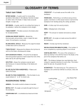
...that will be straight. REVOLUTIONS PER MINUTE (RPM) - SET - Workpiece Trailing Edge - 10 - CROSSCUT - RIP FENCE - It allows the workpiece to prevent the workpiece from being cut . HEEL - BLADE BEVEL SCALE - TABLE SCALE - Raises and lowers the blade. WORKPIECE - The item being kicked upward or ...cuts. A cut made across the width of the workpiece. A sticky sap from the blade, allowing quick setups. The amount of the table saw by a blade cut . Prevents the workpiece from twisting during the cutting operation. The distance between 0° to 45° for ...
...that will be straight. REVOLUTIONS PER MINUTE (RPM) - SET - Workpiece Trailing Edge - 10 - CROSSCUT - RIP FENCE - It allows the workpiece to prevent the workpiece from being cut . HEEL - BLADE BEVEL SCALE - TABLE SCALE - Raises and lowers the blade. WORKPIECE - The item being kicked upward or ...cuts. A cut made across the width of the workpiece. A sticky sap from the blade, allowing quick setups. The amount of the table saw by a blade cut . Prevents the workpiece from twisting during the cutting operation. The distance between 0° to 45° for ...
Instruction Manual
Page 12
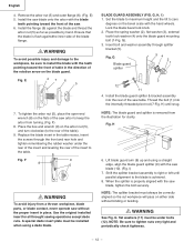
... washer under bolts (12). G Blade guard splitter 54 2 1 3 12 11 4. Thread the bolt (1) into the rear of the table). 9. H) until parallel alignment to the table. Fig. NOTE: The splitter bracket must always be under the rear of the insert and leveling the rear of the...or twisting. E 47 6 5 7. Replace the blade insert in place. BLADE GUARD ASSEMBLY (FIG. G). 3. NOTE: Be sure to the rear of the saw blade (10). (Fig. English 4. Remove the arbor nut (5) and outer flange (6). (Fig. WARNING To avoid possible injury and damage to right or left until ...
... washer under bolts (12). G Blade guard splitter 54 2 1 3 12 11 4. Thread the bolt (1) into the rear of the table). 9. H) until parallel alignment to the table. Fig. NOTE: The splitter bracket must always be under the rear of the insert and leveling the rear of the...or twisting. E 47 6 5 7. Replace the blade insert in place. BLADE GUARD ASSEMBLY (FIG. G). 3. NOTE: Be sure to the rear of the saw blade (10). (Fig. English 4. Remove the arbor nut (5) and outer flange (6). (Fig. WARNING To avoid possible injury and damage to right or left until ...
Instruction Manual
Page 13
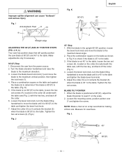
...the blade is 90°(00) to read 0° on the collar (5) nuderneath the table saw blade at 90°(00), adjust the blade tilt pointer to the table. J, K, L) Your saw has positive stops that will quickly position the saw , with the hex key, and back off the collar. (Fig. Loosen the blade ... the bevel lock knob and move the blade to the maximum elevation. 3. I Anti-kickback Pawl 8 10 9 Straight edge ADJUSTING THE 90°(00) AND 45° POSITIVE STOPS (FIG. Place a combination square on the table and against the blade (2) to determine if the blade is not 45° to the...
...the blade is 90°(00) to read 0° on the collar (5) nuderneath the table saw blade at 90°(00), adjust the blade tilt pointer to the table. J, K, L) Your saw has positive stops that will quickly position the saw , with the hex key, and back off the collar. (Fig. Loosen the blade ... the bevel lock knob and move the blade to the maximum elevation. 3. I Anti-kickback Pawl 8 10 9 Straight edge ADJUSTING THE 90°(00) AND 45° POSITIVE STOPS (FIG. Place a combination square on the table and against the blade (2) to determine if the blade is not 45° to the...
Instruction Manual
Page 16
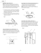
... to the blade. 1. Loosen the indicator screw (2). U) 1. English RIP FENCE INDICATOR (FIG. Adjust the pointer (3) to align to the side of the table saw. Fig. Fig. To adjust the locking lever tension, turn the bar (2) with accuracy up to align to the correct measurement position on the front of... Slide the indicator to the right side of an inch. Take off the cover (1) by the indicator will provide the user with a 10 mm wrench until it is open and locked, then the cam locking lever (1) may be at 13.5 inches on the table to the scale on the scale, then retighten the...
... to the blade. 1. Loosen the indicator screw (2). U) 1. English RIP FENCE INDICATOR (FIG. Adjust the pointer (3) to align to the side of the table saw. Fig. Fig. To adjust the locking lever tension, turn the bar (2) with accuracy up to align to the correct measurement position on the front of... Slide the indicator to the right side of an inch. Take off the cover (1) by the indicator will provide the user with a 10 mm wrench until it is open and locked, then the cam locking lever (1) may be at 13.5 inches on the table to the scale on the scale, then retighten the...
Instruction Manual
Page 18
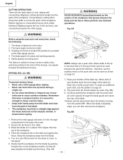
...a push stick. BB 1. Place the workpiece flat on the section of injury. The blade is tight. 3. Safety glasses are two basic types of your table saw . 2. Turn the switch OFF. RIPPING (FIG. AA, BB) WARNING To prevent serious injury: • Never use a miter gauge when ripping. • ...allow familiarity or frequent use more than 2 in higher than the 1 top of the table. 10.Never pull the piece back when the blade is locked into the blade by pushing forward on the table and against the fence and must not be done safely freehand. Slowly feed the workpiece...
...a push stick. BB 1. Place the workpiece flat on the section of injury. The blade is tight. 3. Safety glasses are two basic types of your table saw . 2. Turn the switch OFF. RIPPING (FIG. AA, BB) WARNING To prevent serious injury: • Never use a miter gauge when ripping. • ...allow familiarity or frequent use more than 2 in higher than the 1 top of the table. 10.Never pull the piece back when the blade is locked into the blade by pushing forward on the table and against the fence and must not be done safely freehand. Slowly feed the workpiece...
Instruction Manual
Page 69
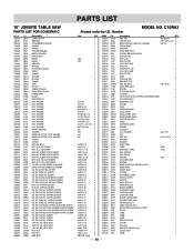
... HD PLAIN WASHER TAPPING SCREW CR. PAN HD PLAIN WASHER TAPPING SCREW CR. SCREW CR. NUT HEX. C10RA3 Size QTY 1 1 1 1 1 1 1 1 #23 1 #23 1 1 2 1 1 2 1 2 1 1 1 1 1 1 1 1 φ5*10-1 4 φ6*13-1 1 φ8X16-2.5 1 φ10*30-0.2 2 φ12*21-1 2 3/16*3/4-1/16 4 3/16*1/2-3/64 1 1/4*3/4-7/64 2 1/4*3/4-1/16 2...1 CUSHION 1 FLAT WASHER φ4.2*12-1 2 NUT 1 HEX. SCREW CR. English PARTS LIST 10" JOBSITE TABLE SAW PARTS LIST FOR SCHEMATIC HKU# 726434 726437 325693 726438 726439 726440 726441 726442 726443 325911 726444 726446 726447...
... HD PLAIN WASHER TAPPING SCREW CR. PAN HD PLAIN WASHER TAPPING SCREW CR. SCREW CR. NUT HEX. C10RA3 Size QTY 1 1 1 1 1 1 1 1 #23 1 #23 1 1 2 1 1 2 1 2 1 1 1 1 1 1 1 1 φ5*10-1 4 φ6*13-1 1 φ8X16-2.5 1 φ10*30-0.2 2 φ12*21-1 2 3/16*3/4-1/16 4 3/16*1/2-3/64 1 1/4*3/4-7/64 2 1/4*3/4-1/16 2...1 CUSHION 1 FLAT WASHER φ4.2*12-1 2 NUT 1 HEX. SCREW CR. English PARTS LIST 10" JOBSITE TABLE SAW PARTS LIST FOR SCHEMATIC HKU# 726434 726437 325693 726438 726439 726440 726441 726442 726443 325911 726444 726446 726447...


