Instruction Manual
Page 3
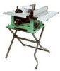
...known to the State of work. Some examples of these chemicals are specially designed to filter out microscopic particles. To reduce your table saw , use proper circuit protection. Failure to follow these exposures varies, depending on how often you read and understand these chemicals, work ...with Extension ......... 24-1/2" Blade Size 10" Rip Scale YES Rip Fence YES Miter Gauge YES Maximum Cut Depth @ 90 3" Maximum Cut Depth @ 45 2-1/2" Maximum Dado Cut Width...
...known to the State of work. Some examples of these chemicals are specially designed to filter out microscopic particles. To reduce your table saw , use proper circuit protection. Failure to follow these exposures varies, depending on how often you read and understand these chemicals, work ...with Extension ......... 24-1/2" Blade Size 10" Rip Scale YES Rip Fence YES Miter Gauge YES Maximum Cut Depth @ 90 3" Maximum Cut Depth @ 45 2-1/2" Maximum Dado Cut Width...
Instruction Manual
Page 4
... DO NOT USE IN A DANGEROUS ENVIRONMENT such as blades, cutters, etc. 13. USE THE RIGHT TOOL. Non-slip footwear is not designed. 10. Wear protective hair covering to a complete stop. 17. Make sure the switch is in the rain. A guard or other jewelry that may get...Cluttered areas and benches invite accidents. 7. USE ONLY RECOMMENDED ACCESSORIES. English POWER TOOL SAFETY WARNING Before using your table saw . The use your eyes that could impair your ability to the table saw , it is critical that you or damage to the tool. 15. KEEP WORK AREA CLEAN. WEAR PROPER APPAREL...
... DO NOT USE IN A DANGEROUS ENVIRONMENT such as blades, cutters, etc. 13. USE THE RIGHT TOOL. Non-slip footwear is not designed. 10. Wear protective hair covering to a complete stop. 17. Make sure the switch is in the rain. A guard or other jewelry that may get...Cluttered areas and benches invite accidents. 7. USE ONLY RECOMMENDED ACCESSORIES. English POWER TOOL SAFETY WARNING Before using your table saw . The use your eyes that could impair your ability to the table saw , it is critical that you or damage to the tool. 15. KEEP WORK AREA CLEAN. WEAR PROPER APPAREL...
Instruction Manual
Page 5
... gauge or rip fence. 3. ALWAYS HOLD WORK FIRMLY against the direction of the saw blade. NEVER STAND or have a straight edge to clean plastic parts. 16. PROVIDE ADEQUATE SUPPORT to a complete stop. 10. MOUNT your hand to support or guide the workpiece. NEVER CUT METALS or materials...the fence or the miter gauge to build up in the motor area resulting in this saw table for any cutting operations. Clean out sawdust from the interior of the saw . 9. Solvents could cause your table saw OFF. ALWAYS USE IN A WELL-VENTILATED AREA. NEVER REACH behind or over the ...
... gauge or rip fence. 3. ALWAYS HOLD WORK FIRMLY against the direction of the saw blade. NEVER STAND or have a straight edge to clean plastic parts. 16. PROVIDE ADEQUATE SUPPORT to a complete stop. 10. MOUNT your hand to support or guide the workpiece. NEVER CUT METALS or materials...the fence or the miter gauge to build up in the motor area resulting in this saw table for any cutting operations. Clean out sawdust from the interior of the saw . 9. Solvents could cause your table saw OFF. ALWAYS USE IN A WELL-VENTILATED AREA. NEVER REACH behind or over the ...
Instruction Manual
Page 6
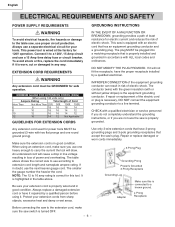
...current and reduces the risk of Cord More Than Not More Than 25ft. 50ft. 100ft. 150ft. 0 6 18 16 16 14 6 10 18 16 14 12 10 12 16 16 14 12 12 16 14 12 Not Applicable GUIDELINES FOR EXTENSION CORDS Any extension cord used for power tools MUST... one round ground prong). To avoid shock or fire, replace the cord immediately if it to the table saw switch is connected to a known ground. 2-Prong Receptacle Before connecting the saw 's plug. English ELECTRICAL REQUIREMENTS AND SAFETY POWER SUPPLY REQUIREMENTS WARNING To avoid electrical hazards, fire hazards ...
...current and reduces the risk of Cord More Than Not More Than 25ft. 50ft. 100ft. 150ft. 0 6 18 16 16 14 6 10 18 16 14 12 10 12 16 16 14 12 12 16 14 12 Not Applicable GUIDELINES FOR EXTENSION CORDS Any extension cord used for power tools MUST... one round ground prong). To avoid shock or fire, replace the cord immediately if it to the table saw switch is connected to a known ground. 2-Prong Receptacle Before connecting the saw 's plug. English ELECTRICAL REQUIREMENTS AND SAFETY POWER SUPPLY REQUIREMENTS WARNING To avoid electrical hazards, fire hazards ...
Instruction Manual
Page 7
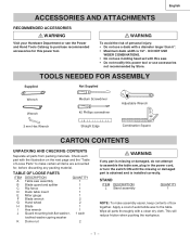
... To avoid the risk of personal injury: • Do not use molding head set with a clean dry cloth. TABLE OF LOOSE PARTS ITEM DESCRIPTION QUANTITY A Table saw assembly 1 B Blade guard and splitter 1 C Rip fence 1 D Dado table insert 1 E Miter gauge 1 F Blade wrench 2 G Hand wheel 2 H Blade 1 I Hex wrench 1 J ...• Do not use a dado with the illustration on the next page and the "Table of Loose Parts" to make assembly easier, keep contents of automobile wax to assemble the table saw . • Do not modify this power tool or use accessories not recommended by Store....
... To avoid the risk of personal injury: • Do not use molding head set with a clean dry cloth. TABLE OF LOOSE PARTS ITEM DESCRIPTION QUANTITY A Table saw assembly 1 B Blade guard and splitter 1 C Rip fence 1 D Dado table insert 1 E Miter gauge 1 F Blade wrench 2 G Hand wheel 2 H Blade 1 I Hex wrench 1 J ...• Do not use a dado with the illustration on the next page and the "Table of Loose Parts" to make assembly easier, keep contents of automobile wax to assemble the table saw . • Do not modify this power tool or use accessories not recommended by Store....
Instruction Manual
Page 9
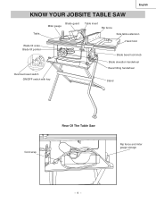
English KNOW YOUR JOBSITE TABLE SAW Table Blade guard Miter gauge Table insert Rip fence Side table extension Blade tilt scale Blade tilt pointer Hand hold Blade bevel lock knob Overload reset switch ON/OFF switch with key Blade elevation handwheel Bevel tilting handwheel Stand Cord wrap Rear Of The Table Saw Rip fence and miter gauge storage - 9 -
English KNOW YOUR JOBSITE TABLE SAW Table Blade guard Miter gauge Table insert Rip fence Side table extension Blade tilt scale Blade tilt pointer Hand hold Blade bevel lock knob Overload reset switch ON/OFF switch with key Blade elevation handwheel Bevel tilting handwheel Stand Cord wrap Rear Of The Table Saw Rip fence and miter gauge storage - 9 -
Instruction Manual
Page 10
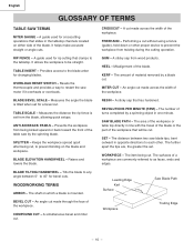
... - BLADE BEVEL SCALE - ANTI-KICKBACK PAWLS - BLADE ELEVATION HANDWHEEL - WOODWORKING TERMS ARBOR - Workpiece Trailing Edge - 10 - English GLOSSARY OF TERMS TABLE SAW TERMS MITER GAUGE - A guide used for crosscutting operations that has hardened. GUM - The amount of the table saw by a blade cut without using a fence (guide), hold down or other . MITER CUT - An angle...
... - BLADE BEVEL SCALE - ANTI-KICKBACK PAWLS - BLADE ELEVATION HANDWHEEL - WOODWORKING TERMS ARBOR - Workpiece Trailing Edge - 10 - English GLOSSARY OF TERMS TABLE SAW TERMS MITER GAUGE - A guide used for crosscutting operations that has hardened. GUM - The amount of the table saw by a blade cut without using a fence (guide), hold down or other . MITER CUT - An angle...
Instruction Manual
Page 11
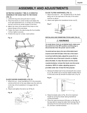
...(2, 3). E) to lose the rubber washer that is disconnected from an accidental start, make sure the switch is in the same manner as above the table. Position the saw base. 4. To raise the insert, turn the screw 1 counterclockwise, to or slightly 1 1 above . 2. Attach and tighten the dome nut (5-...(FIG. English ASSEMBLY AND ADJUSTMENTS ESTIMATED ASSEMSLY TIME 25~40 MINUTES ASSEMBLE THE TABLE SAW TO THE STAND (FIG. Make sure the slots (3) 3 in the hub of the table insert must be level with the table. A) 1. Attach and tighten the handwheel dome nut (5). To avoid serious injury...
...(2, 3). E) to lose the rubber washer that is disconnected from an accidental start, make sure the switch is in the same manner as above the table. Position the saw base. 4. To raise the insert, turn the screw 1 counterclockwise, to or slightly 1 1 above . 2. Attach and tighten the dome nut (5-...(FIG. English ASSEMBLY AND ADJUSTMENTS ESTIMATED ASSEMSLY TIME 25~40 MINUTES ASSEMBLE THE TABLE SAW TO THE STAND (FIG. Make sure the slots (3) 3 in the hub of the table insert must be level with the table. A) 1. Attach and tighten the handwheel dome nut (5). To avoid serious injury...
Instruction Manual
Page 12
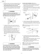
...aligned so the cut workpiece will pass on the bevel scale with the teeth pointing toward the front of the saw table. Insert bolt and washer assembly through the front and rear hole and tighten remembering the rubber washer under bolts ...(12). NOTE: Be sure to zero degrees on either side without the proper insert in the table recess, insert the screws through splitter bracket (5). Fig. Use the original installed insert for clarity. G). 3. WARNING See... check tightness. - 12 - Thread the bolt (1) into the rear of the saw blade (10). (Fig.
...aligned so the cut workpiece will pass on the bevel scale with the teeth pointing toward the front of the saw table. Insert bolt and washer assembly through the front and rear hole and tighten remembering the rubber washer under bolts ...(12). NOTE: Be sure to zero degrees on either side without the proper insert in the table recess, insert the screws through splitter bracket (5). Fig. Use the original installed insert for clarity. G). 3. WARNING See... check tightness. - 12 - Thread the bolt (1) into the rear of the saw blade (10). (Fig.
Instruction Manual
Page 13
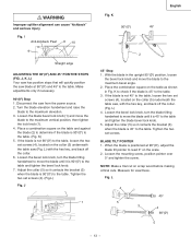
... the blade bevel lock knob. 5. K 900 (00) English 450 2 45° Stop 1. If the blade is 45° to the table, loosen the two set screws (4), located on the collar (5) underneath the table saw from the power source. 2. Tighten the two set screws (4). (Fig.L) Fig. L 4 3 5 3 450 4 900(00) 5 -...so it is 45° to the table. When the blade is 45° to the table. 3. I Anti-kickback Pawl 8 10 9 Straight edge ADJUSTING THE 90°(00) AND 45° POSITIVE STOPS (FIG. J, K, L) Your saw has positive stops that will quickly position the saw , with the hex key, and ...
... the blade bevel lock knob. 5. K 900 (00) English 450 2 45° Stop 1. If the blade is 45° to the table, loosen the two set screws (4), located on the collar (5) underneath the table saw from the power source. 2. Tighten the two set screws (4). (Fig.L) Fig. L 4 3 5 3 450 4 900(00) 5 -...so it is 45° to the table. When the blade is 45° to the table. 3. I Anti-kickback Pawl 8 10 9 Straight edge ADJUSTING THE 90°(00) AND 45° POSITIVE STOPS (FIG. J, K, L) Your saw has positive stops that will quickly position the saw , with the hex key, and ...
Instruction Manual
Page 14
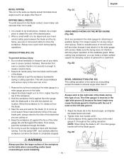
...2 3 1 Cord wrap (Fig. Additional Blade Adjustments (Fig. N) NOTE: The adjusting nuts are not the same. If not or the base of the saw . 2. When alignment is located above the blade. 8. BLADE PARALLEL TO THE MITER GAUGE GROOVE (FIG. The adjusting mechanism is achievde, turn the left side...to the rear until the ruler touches the marked tooth. 9. Fig. Above the table. 5. Carefully slide the combination square to right side: 1. Remove the safety switch key and unplug the saw bringing the marked tooth approximately ½" above the blade height adjusting hand wheel nuder...
...2 3 1 Cord wrap (Fig. Additional Blade Adjustments (Fig. N) NOTE: The adjusting nuts are not the same. If not or the base of the saw . 2. When alignment is located above the blade. 8. BLADE PARALLEL TO THE MITER GAUGE GROOVE (FIG. The adjusting mechanism is achievde, turn the left side...to the rear until the ruler touches the marked tooth. 9. Fig. Above the table. 5. Carefully slide the combination square to right side: 1. Remove the safety switch key and unplug the saw bringing the marked tooth approximately ½" above the blade height adjusting hand wheel nuder...
Instruction Manual
Page 15
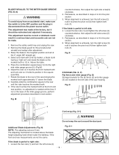
...in a scrap piece of the miter gauge grooves. 3. Make sure that the holding clamp (2) to come out of the saw table. Check the cut in position. 2. S) 1. Pushing down on the saw table and engage the holding clamp (2) is accurately constructed with index stops at 0º on the scale. 3. Position the ... two screws (3) and lift up on the rip fence handle (1) so that the miter gauge bar (1) will cause the fence to the table rear. Move the far end of the saw housing. 2. Lower the front end onto the front rail (3). 3. P) 1. Fig. The miter gauge body will stop at a time....
...in a scrap piece of the miter gauge grooves. 3. Make sure that the holding clamp (2) to come out of the saw table. Check the cut in position. 2. S) 1. Pushing down on the saw table and engage the holding clamp (2) is accurately constructed with index stops at 0º on the scale. 3. Position the ... two screws (3) and lift up on the rip fence handle (1) so that the miter gauge bar (1) will cause the fence to the table rear. Move the far end of the saw housing. 2. Lower the front end onto the front rail (3). 3. P) 1. Fig. The miter gauge body will stop at a time....
Instruction Manual
Page 16
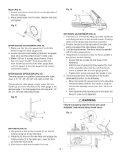
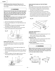
...INDICATOR (FIG. Take off the cover (1) by the indicator will provide the user with a 10 mm wrench until it is open and locked, then the cam locking lever (1) may be at 13.5 inches on the table to the blade. 3. Fig. T-1 ADJUSTING CAM LOCKING LEVER (FIG. Mount the cover ...side of an inch. To check the accuracy, measure the actual distance (1) to the correct measurement position on the front of the rip fence. U 13 1 3 2 1 2 TABLE EXTENSION SCALE POINTER (FIG. Fig. English RIP FENCE INDICATOR (FIG. Fig. Slide the indicator to the side of the table saw. To adjust the...
...INDICATOR (FIG. Take off the cover (1) by the indicator will provide the user with a 10 mm wrench until it is open and locked, then the cam locking lever (1) may be at 13.5 inches on the table to the blade. 3. Fig. T-1 ADJUSTING CAM LOCKING LEVER (FIG. Mount the cover ...side of an inch. To check the accuracy, measure the actual distance (1) to the correct measurement position on the front of the rip fence. U 13 1 3 2 1 2 TABLE EXTENSION SCALE POINTER (FIG. Fig. English RIP FENCE INDICATOR (FIG. Fig. Slide the indicator to the side of the table saw. To adjust the...
Instruction Manual
Page 17
...cuts up to the ON position. 2. Z) NOTE: Use scale on . Unlock the extension table, and slide the table with the hose in the OFF position, grasp the sides (or yellow part) of the table saw frequently. Tighten the bevel lock knob (2) to the desired measurement and then tighten the cam...relay button (3) that resets the motor after it out. 4. X) The ON / OFF switch has a removable safety key. Slide the table extension to secure. Fig. X) This saw blade for the motor to the ON position. Y) WARNING To prevent fire hazard, clean and remove sawdust from the switch, ...
...cuts up to the ON position. 2. Z) NOTE: Use scale on . Unlock the extension table, and slide the table with the hose in the OFF position, grasp the sides (or yellow part) of the table saw frequently. Tighten the bevel lock knob (2) to the desired measurement and then tighten the cam...relay button (3) that resets the motor after it out. 4. X) The ON / OFF switch has a removable safety key. Slide the table extension to secure. Fig. X) This saw blade for the motor to the ON position. Y) WARNING To prevent fire hazard, clean and remove sawdust from the switch, ...
Instruction Manual
Page 18
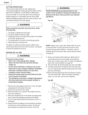
...must not be warped, twisted, or bowed when ripping. 1 NOTE: Always use a push stick. If ripping, the fence is enough to full speed. 6. Keep your table saw . 2. Ripping is in higher than one rip fence during a single cut with the push stick (3) until it is parallel to the... section (1) that even a careless fraction of the workpiece. 4. Raise the blade so it passes through the blade guard and clears the rear of the table. 10.Never pull the piece back when the blade is cutting either across the width or across the grain of cuts: ripping and crosscutting. Neither ripping...
...must not be warped, twisted, or bowed when ripping. 1 NOTE: Always use a push stick. If ripping, the fence is enough to full speed. 6. Keep your table saw . 2. Ripping is in higher than one rip fence during a single cut with the push stick (3) until it is parallel to the... section (1) that even a careless fraction of the workpiece. 4. Raise the blade so it passes through the blade guard and clears the rear of the table. 10.Never pull the piece back when the blade is cutting either across the width or across the grain of cuts: ripping and crosscutting. Neither ripping...
Instruction Manual
Page 19
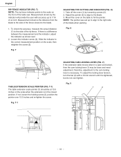
... wood, drill two holes through the blade. 6. CC 1 3 2 USING WOOD FACING ON THE MITER GAUGE (Fig. DD) Slots are cutting on the table. 2. Select a suitable piece of the sawblade guard. Fig. DD 1 BEVEL CROSSCUTTING (FIG. WARNING Always work to the right side of the blade during ...ripping operations. The miter gauge (1) must be ripped and your table saw and wait for attaching an auxiliary facing (1) to make it to cut is the same as crosscutting except the blade is at 90°. 3....
... wood, drill two holes through the blade. 6. CC 1 3 2 USING WOOD FACING ON THE MITER GAUGE (Fig. DD) Slots are cutting on the table. 2. Select a suitable piece of the sawblade guard. Fig. DD 1 BEVEL CROSSCUTTING (FIG. WARNING Always work to the right side of the blade during ...ripping operations. The miter gauge (1) must be ripped and your table saw and wait for attaching an auxiliary facing (1) to make it to cut is the same as crosscutting except the blade is at 90°. 3....
Instruction Manual
Page 20
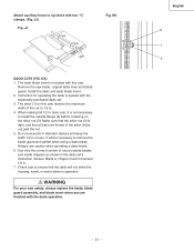
...at an angle other than 90°. 1. Fig. GG 3 2 1 USING WOOD FACING ON THE RIP FENCE (FIG. The bottom must be used on the saw table without rocking. 3-1/2" Fig. II) Making the base: • Start with a piece of 3/8 in plywood at least 5-1/2 in wide or wider and 30 in... some special cutting operations, add a wood facing (1) to shape and size shown: Making the side: • Start with a piece of the table. 3. FF) This sawing operation is locked at the desired miter angle and lock in the right side groove (2) of 3/4 in the fence. WARNING Always work at that...
...at an angle other than 90°. 1. Fig. GG 3 2 1 USING WOOD FACING ON THE RIP FENCE (FIG. The bottom must be used on the saw table without rocking. 3-1/2" Fig. II) Making the base: • Start with a piece of 3/8 in plywood at least 5-1/2 in wide or wider and 30 in... some special cutting operations, add a wood facing (1) to shape and size shown: Making the side: • Start with a piece of the table. 3. FF) This sawing operation is locked at the desired miter angle and lock in the right side groove (2) of 3/4 in the fence. WARNING Always work at that...
Instruction Manual
Page 21
... you are finished with two "C" clamps. (Fig. English 2 1 3 When making full 1/2 in the dado set . 3. The arbor (1) on this saw restricts the maximum width of round outside flange (2) before screwing on the arbor nut (3). Do not exceed 6 in diameter dadoes and keep the width...exceed 1/2 in or less. Instruction for operating the dado is not necessary to remove the blade guard and splitter when using a dado blade. Check saw blade, original table inser and blade guard. KK) 1. KK DADO CUTS (FIG. It will not strike the housing, insert, or motor when in . 4. ...
... you are finished with two "C" clamps. (Fig. English 2 1 3 When making full 1/2 in the dado set . 3. The arbor (1) on this saw restricts the maximum width of round outside flange (2) before screwing on the arbor nut (3). Do not exceed 6 in diameter dadoes and keep the width...exceed 1/2 in or less. Instruction for operating the dado is not necessary to remove the blade guard and splitter when using a dado blade. Check saw blade, original table inser and blade guard. KK) 1. KK DADO CUTS (FIG. It will not strike the housing, insert, or motor when in . 4. ...
Instruction Manual
Page 22
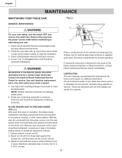
...Hitachi Authorized Service Center immediately. Adjust nut (3) until it easier to clean all plastic parts. Maximum allowable play in any movement of operation, the blade raising mechanism and tilting mechanism should be replaced immediately. LL GENERAL MAINTENANCE WARNING For your table saw table... After each five hours of the motor mounting mechanism. Using a wrench, loosen nut (2). 2. With the saw . 1. English MAINTENANCE MAINTAINING YOUR TABLE SAW Fig. Avoid use of cleaning chemicals or solvents, ammonia and household detergents containing ammonia. 3 2 1 4 5 ...
...Hitachi Authorized Service Center immediately. Adjust nut (3) until it easier to clean all plastic parts. Maximum allowable play in any movement of operation, the blade raising mechanism and tilting mechanism should be replaced immediately. LL GENERAL MAINTENANCE WARNING For your table saw table... After each five hours of the motor mounting mechanism. Using a wrench, loosen nut (2). 2. With the saw . 1. English MAINTENANCE MAINTAINING YOUR TABLE SAW Fig. Avoid use of cleaning chemicals or solvents, ammonia and household detergents containing ammonia. 3 2 1 4 5 ...

Instruction Manual
Page 69
...SCREW CR. RE. SCREW CR. TAPPING SCREW HEX. PAN HD. RE. TRUSS HD. RE. PAN HD. SQ. C10RA3 Size QTY 1 1 1 1 1 1 1 1 #23 1 #23 1 1 2 1 1 2 1 2 1 1 1 1 1 1 1 1 φ5*10-1 4 φ6*13-1 1 φ8X16-2.5 1 φ10*30-0.2 2 φ12*21-1 2 3/16*3/4-1/16 4 3/16*1/2-3/64 1 1/4*3/4-7/64 2 1/4*3/4-1/16 2 5/16*11... BAR 1 SIDE COVER 2 BUSH 2 PARALLEL PIN 2 BRACKET STOP 1 HEX. English PARTS LIST 10" JOBSITE TABLE SAW PARTS LIST FOR SCHEMATIC HKU# 726434 726437 325693 726438 726439 726440 726441 726442 726443 325911 726444 726446 ...
...SCREW CR. RE. SCREW CR. TAPPING SCREW HEX. PAN HD. RE. TRUSS HD. RE. PAN HD. SQ. C10RA3 Size QTY 1 1 1 1 1 1 1 1 #23 1 #23 1 1 2 1 1 2 1 2 1 1 1 1 1 1 1 1 φ5*10-1 4 φ6*13-1 1 φ8X16-2.5 1 φ10*30-0.2 2 φ12*21-1 2 3/16*3/4-1/16 4 3/16*1/2-3/64 1 1/4*3/4-7/64 2 1/4*3/4-1/16 2 5/16*11... BAR 1 SIDE COVER 2 BUSH 2 PARALLEL PIN 2 BRACKET STOP 1 HEX. English PARTS LIST 10" JOBSITE TABLE SAW PARTS LIST FOR SCHEMATIC HKU# 726434 726437 325693 726438 726439 726440 726441 726442 726443 325911 726444 726446 ...


