Instruction Manual
Page 7
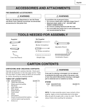
... PARTS ITEM DESCRIPTION QUANTITY A Table saw assembly 1 B Blade guard and splitter 1 C Rip fence 1 D Dado table insert 1 E Miter gauge 1 F Blade wrench 2 G Hand wheel 2 H Blade 1 I Hex wrench 1 J Guard mounting bolt,flat washer, 1 each part with this power tool. This will ...the Power and Hand Tools Catalog to purchase recommended accessories for , before discarding any part is missing or damaged, do not attempt to assemble the table saw . • Do not modify this power tool or use a dado with a clean dry cloth. WARNING To avoid the risk of automobile wax ...
... PARTS ITEM DESCRIPTION QUANTITY A Table saw assembly 1 B Blade guard and splitter 1 C Rip fence 1 D Dado table insert 1 E Miter gauge 1 F Blade wrench 2 G Hand wheel 2 H Blade 1 I Hex wrench 1 J Guard mounting bolt,flat washer, 1 each part with this power tool. This will ...the Power and Hand Tools Catalog to purchase recommended accessories for , before discarding any part is missing or damaged, do not attempt to assemble the table saw . • Do not modify this power tool or use a dado with a clean dry cloth. WARNING To avoid the risk of automobile wax ...
Instruction Manual
Page 9
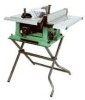
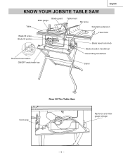
English KNOW YOUR JOBSITE TABLE SAW Table Blade guard Miter gauge Table insert Rip fence Side table extension Blade tilt scale Blade tilt pointer Hand hold Blade bevel lock knob Overload reset switch ON/OFF switch with key Blade elevation handwheel Bevel tilting handwheel Stand Cord wrap Rear Of The Table Saw Rip fence and miter gauge storage - 9 -
English KNOW YOUR JOBSITE TABLE SAW Table Blade guard Miter gauge Table insert Rip fence Side table extension Blade tilt scale Blade tilt pointer Hand hold Blade bevel lock knob Overload reset switch ON/OFF switch with key Blade elevation handwheel Bevel tilting handwheel Stand Cord wrap Rear Of The Table Saw Rip fence and miter gauge storage - 9 -
Instruction Manual
Page 10
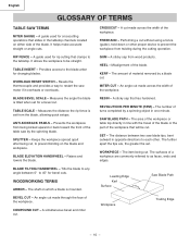
It helps make accurate straight or angle cuts. TABLE INSERT - HEEL - Misalignment of the table saw by the spinning blade. An angle cut , to prevent binding on which a blade is mounted. TABLE SCALE - RESIN - SAW BLADE PATH - The surfaces of the workpiece. WOODWORKING TERMS ARBOR - The ... of the workpiece or table top directly in one minute. The item being kicked upward or back toward the front of the blade. BLADE ELEVATION HANDWHEEL - CROSSCUT - WORKPIECE - Workpiece Trailing Edge - 10 - English GLOSSARY OF TERMS TABLE SAW TERMS MITER GAUGE - ...
It helps make accurate straight or angle cuts. TABLE INSERT - HEEL - Misalignment of the table saw by the spinning blade. An angle cut , to prevent binding on which a blade is mounted. TABLE SCALE - RESIN - SAW BLADE PATH - The surfaces of the workpiece. WOODWORKING TERMS ARBOR - The ... of the workpiece or table top directly in one minute. The item being kicked upward or back toward the front of the blade. BLADE ELEVATION HANDWHEEL - CROSSCUT - WORKPIECE - Workpiece Trailing Edge - 10 - English GLOSSARY OF TERMS TABLE SAW TERMS MITER GAUGE - ...
Instruction Manual
Page 11
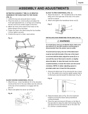
... handwheel (1) engage with the pins (4). 2. F) and place the box-end wrench (9) on the bottom flange of the saw base. 4. Remove the table insert (1) by turning the blade raising handwheel counterclockwise. 3. D BLADE RAISING HANDWHEEL (FIG. A BLADE TILTING HANDWHEEL (FIG. D) Fig....level to the elevation rod (2) at similar angles on the back screw (3) beneath the table insert. (Fig. Fasten the saw on the right side of the saw in or out until the rear of insert for this purpose. 1. Unfold the leg sets and push down handwheel (1) to or slightly...
... handwheel (1) engage with the pins (4). 2. F) and place the box-end wrench (9) on the bottom flange of the saw base. 4. Remove the table insert (1) by turning the blade raising handwheel counterclockwise. 3. D BLADE RAISING HANDWHEEL (FIG. A BLADE TILTING HANDWHEEL (FIG. D) Fig....level to the elevation rod (2) at similar angles on the back screw (3) beneath the table insert. (Fig. Fasten the saw on the right side of the saw in or out until the rear of insert for this purpose. 1. Unfold the leg sets and push down handwheel (1) to or slightly...
Instruction Manual
Page 12
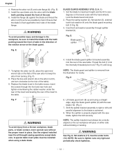
... washer (2), flat washers (11) must be correctly aligned so the cut workpiece will pass on the bevel scale with the saw blade (10). (Fig. Fig. NOTE: The splitter bracket must always be installed when using a straight edge, align the blade guard splitter ... nut (5), and turn clockwise (to zero degrees on either side without the proper insert in the table recess, insert the screws through splitter bracket (5). G). 3. Thread the bolt (1) into the rear of the saw table. When the splitter is achieved. 8. Install the blade guard splitter & bracket assembly...
... washer (2), flat washers (11) must be correctly aligned so the cut workpiece will pass on the bevel scale with the saw blade (10). (Fig. Fig. NOTE: The splitter bracket must always be installed when using a straight edge, align the blade guard splitter ... nut (5), and turn clockwise (to zero degrees on either side without the proper insert in the table recess, insert the screws through splitter bracket (5). G). 3. Thread the bolt (1) into the rear of the saw table. When the splitter is achieved. 8. Install the blade guard splitter & bracket assembly...
Instruction Manual
Page 17
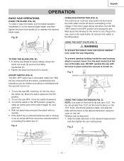
... the motor stops during operation, turn the saw ON, insert key (1) into the slot in the saw blade for bevel cutting, loosen the bevel lock knob (2) and turn the saw OFF, move the switch downward. 3. Fig. Fig. DO NOT operate the saw has an overload relay button (3) that resets...tighten the bevel lock handle (2) to the ON position. 2. Unlock the extension table, and slide the table with the hose in the OFF position, grasp the sides (or yellow part) of the table saw frequently. X 2 1 USING THE TABLE EXTENSION (FIG. W) To raise or lower the blade, turn on the 13.5"...
... the motor stops during operation, turn the saw ON, insert key (1) into the slot in the saw blade for bevel cutting, loosen the bevel lock knob (2) and turn the saw OFF, move the switch downward. 3. Fig. Fig. DO NOT operate the saw has an overload relay button (3) that resets...tighten the bevel lock handle (2) to the ON position. 2. Unlock the extension table, and slide the table with the hose in the OFF position, grasp the sides (or yellow part) of the table saw frequently. X 2 1 USING THE TABLE EXTENSION (FIG. W) To raise or lower the blade, turn on the 13.5"...
Instruction Manual
Page 21
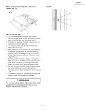
...Blade or chipper must not exceed 1/2 in or less. WARNING For your own safety, always replace the blade, blade guard assembly, and blade insert when you are finished with the separately purchased dado set 's instruction manual. JJ) Fig. Instruction for operating the dado is tight,... and that the dado will be necessary to rip fence with this saw blade, original table inser and blade guard. Always use caution when operating a dado blade. 6. Attach auxiliary fence to remove the blade guard and splitter ...
...Blade or chipper must not exceed 1/2 in or less. WARNING For your own safety, always replace the blade, blade guard assembly, and blade insert when you are finished with the separately purchased dado set 's instruction manual. JJ) Fig. Instruction for operating the dado is tight,... and that the dado will be necessary to rip fence with this saw blade, original table inser and blade guard. Always use caution when operating a dado blade. 6. Attach auxiliary fence to remove the blade guard and splitter ...
Instruction Manual
Page 69
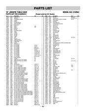
... RE. TRUSS HD. RE. SCREW & WASHER CR.RE. PAN HD. TAPPING SCREW CR. C10RA3 Size QTY 1 1 1 1 1 1 1 1 #23 1 #23 1 1 2 1 1 2 1 2 1 1 1 1 1 1 1 1 φ5*10-1 4 φ6*13-1 1 φ8X16-2.5 1 φ10*30-0.2 2 φ12*21-1 2 3/16*3/4-1/16 4 3/16*1/2-3/64 1 1/4*3/4-7/64 2 ...TRUSS HD. NECK BOLT CAP HD. English PARTS LIST 10" JOBSITE TABLE SAW PARTS LIST FOR SCHEMATIC HKU# 726434 726437 325693 726438 726439...SADDLE SPRING POINTER BRACKET NEEDLE POINTER SWITCH BOX INSERT INSERT WRENCH SPACER PLUNGER HOUSING STRAP CLAMP SPACER SPACER...
... RE. TRUSS HD. RE. SCREW & WASHER CR.RE. PAN HD. TAPPING SCREW CR. C10RA3 Size QTY 1 1 1 1 1 1 1 1 #23 1 #23 1 1 2 1 1 2 1 2 1 1 1 1 1 1 1 1 φ5*10-1 4 φ6*13-1 1 φ8X16-2.5 1 φ10*30-0.2 2 φ12*21-1 2 3/16*3/4-1/16 4 3/16*1/2-3/64 1 1/4*3/4-7/64 2 ...TRUSS HD. NECK BOLT CAP HD. English PARTS LIST 10" JOBSITE TABLE SAW PARTS LIST FOR SCHEMATIC HKU# 726434 726437 325693 726438 726439...SADDLE SPRING POINTER BRACKET NEEDLE POINTER SWITCH BOX INSERT INSERT WRENCH SPACER PLUNGER HOUSING STRAP CLAMP SPACER SPACER...