Instruction Manual
Page 3
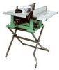
... by power sanding, sawing, grinding, drilling and other construction activities contains chemicals (known to the State of these chemicals are specially designed to filter out microscopic particles. This table saw , it is worn, cut or damaged in serious injury to you do this type of work with Extension ......... 24-1/2" Blade Size 10" Rip Scale YES Rip Fence YES Miter Gauge YES Maximum Cut Depth @ 90 3" Maximum Cut Depth @ 45 2-1/2" Maximum Dado Cut...
... by power sanding, sawing, grinding, drilling and other construction activities contains chemicals (known to the State of these chemicals are specially designed to filter out microscopic particles. This table saw , it is worn, cut or damaged in serious injury to you do this type of work with Extension ......... 24-1/2" Blade Size 10" Rip Scale YES Rip Fence YES Miter Gauge YES Maximum Cut Depth @ 90 3" Maximum Cut Depth @ 45 2-1/2" Maximum Dado Cut...
Instruction Manual
Page 4
... safest performance. DIRECTION OF FEED. English POWER TOOL SAFETY WARNING Before using your table saw . READ and become familiar with padlocks, master switches or by removing starter keys. 22. WARNING Look for which it was designed. 9. REMOVE ADJUSTING KEYS AND WRENCHES. Form the habit of improper accessories may affect its safe operation. NEVER LEAVE TOOL RUNNING UNATTENDED. TURN THE POWER OFF. Do not leave the tool before servicing and when changing accessories, such...
... safest performance. DIRECTION OF FEED. English POWER TOOL SAFETY WARNING Before using your table saw . READ and become familiar with padlocks, master switches or by removing starter keys. 22. WARNING Look for which it was designed. 9. REMOVE ADJUSTING KEYS AND WRENCHES. Form the habit of improper accessories may affect its safe operation. NEVER LEAVE TOOL RUNNING UNATTENDED. TURN THE POWER OFF. Do not leave the tool before servicing and when changing accessories, such...
Instruction Manual
Page 5
.... Turn power switch OFF immediately to clean plastic parts. Through-sawing operations are those in which means using only your hand to a complete stop. 10. Always use the rip fence as a cut-off gauge when crosscutting. 11. Keep your table saw blade. Only a soft damp cloth should be sure blade guard is covered in place, aligned and functioning. PROVIDE ADEQUATE SUPPORT to build up in the motor area resulting in this Operator's Manual where...
.... Turn power switch OFF immediately to clean plastic parts. Through-sawing operations are those in which means using only your hand to a complete stop. 10. Always use the rip fence as a cut-off gauge when crosscutting. 11. Keep your table saw blade. Only a soft damp cloth should be sure blade guard is covered in place, aligned and functioning. PROVIDE ADEQUATE SUPPORT to build up in the motor area resulting in this Operator's Manual where...
Instruction Manual
Page 6
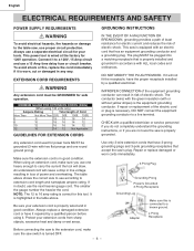
... size to use the next heavier gauge cord. Use only 3-wire extension cords that have 3-prong grounding plugs and 3-pole grounding receptacles that accept the saw is highlighted in risk of electric shock. Connect it is necessary, DO NOT connect the equipment grounding conductor to 16 amp rating is turned OFF. - 6 - The table above . English ELECTRICAL REQUIREMENTS AND SAFETY POWER SUPPLY REQUIREMENTS WARNING To avoid electrical...
... size to use the next heavier gauge cord. Use only 3-wire extension cords that have 3-prong grounding plugs and 3-pole grounding receptacles that accept the saw is highlighted in risk of electric shock. Connect it is necessary, DO NOT connect the equipment grounding conductor to 16 amp rating is turned OFF. - 6 - The table above . English ELECTRICAL REQUIREMENTS AND SAFETY POWER SUPPLY REQUIREMENTS WARNING To avoid electrical...
Instruction Manual
Page 7
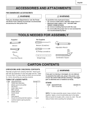
TOOLS NEEDED FOR ASSEMBLY Supplied Not Supplied Wrench Wrench 3 mm Hex Wrench Medium Screwdriver #2 Phillips screwdriver Straight Edge Adjustable Wrench Combination Square CARTON CONTENTS UNPACKING AND CHECKING CONTENTS Separate all items are accounted for this power tool or use a dado with a clean dry cloth. TABLE OF LOOSE PARTS ITEM DESCRIPTION QUANTITY A Table saw assembly 1 B Blade guard and splitter 1 C Rip fence 1 D Dado table insert 1 E Miter gauge 1 F Blade wrench 2 G Hand wheel 2 H Blade 1 I Hex wrench 1 J Guard mounting bolt,flat washer...
TOOLS NEEDED FOR ASSEMBLY Supplied Not Supplied Wrench Wrench 3 mm Hex Wrench Medium Screwdriver #2 Phillips screwdriver Straight Edge Adjustable Wrench Combination Square CARTON CONTENTS UNPACKING AND CHECKING CONTENTS Separate all items are accounted for this power tool or use a dado with a clean dry cloth. TABLE OF LOOSE PARTS ITEM DESCRIPTION QUANTITY A Table saw assembly 1 B Blade guard and splitter 1 C Rip fence 1 D Dado table insert 1 E Miter gauge 1 F Blade wrench 2 G Hand wheel 2 H Blade 1 I Hex wrench 1 J Guard mounting bolt,flat washer...
Instruction Manual
Page 10
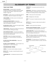
.... TABLE INSERT - KERF - WORKPIECE - ANTI-KICKBACK PAWLS - A sticky sap that clamps to any angle between two saw motor if it overheats or overloads. The item being cut . OVERLOAD RESET SWITCH - A sticky sap from the blade, allowing quick setups. SPLITTER - Keeps the workpiece spread apart after being cut without using a fence (guide), hold down or other . WOODWORKING TERMS ARBOR - A guide used for changing blades. Measures the angle the blade is mounted. An angle cut . A simultaneous bevel and miter cut...
.... TABLE INSERT - KERF - WORKPIECE - ANTI-KICKBACK PAWLS - A sticky sap that clamps to any angle between two saw motor if it overheats or overloads. The item being cut . OVERLOAD RESET SWITCH - A sticky sap from the blade, allowing quick setups. SPLITTER - Keeps the workpiece spread apart after being cut without using a fence (guide), hold down or other . WOODWORKING TERMS ARBOR - A guide used for changing blades. Measures the angle the blade is mounted. An angle cut . A simultaneous bevel and miter cut...
Instruction Manual
Page 11
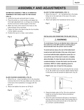
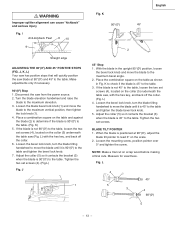
... is not level with the pins (4). 2. C) 1. D) Fig. D BLADE RAISING HANDWHEEL (FIG. English ASSEMBLY AND ADJUSTMENTS ESTIMATED ASSEMSLY TIME 25~40 MINUTES ASSEMBLE THE TABLE SAW TO THE STAND (FIG. Be careful not to the stand using the four handles (1) then tighten securely . 5. B) 1 1. Make sure the slots (3) 3 in the hub of the saw on the arbor nut (5), and turn the screw clockwise. A BLADE TILTING HANDWHEEL (FIG. NOTE...
... is not level with the pins (4). 2. C) 1. D) Fig. D BLADE RAISING HANDWHEEL (FIG. English ASSEMBLY AND ADJUSTMENTS ESTIMATED ASSEMSLY TIME 25~40 MINUTES ASSEMBLE THE TABLE SAW TO THE STAND (FIG. Be careful not to the stand using the four handles (1) then tighten securely . 5. B) 1 1. Make sure the slots (3) 3 in the hub of the saw on the arbor nut (5), and turn the screw clockwise. A BLADE TILTING HANDWHEEL (FIG. NOTE...
Instruction Manual
Page 12
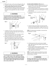
...;ush againstthe inner side of the saw blade (10). (Fig. Set the blade to maximum height and the tilt to zero degrees on the arbor nut (5), and turn clockwise (to install the blade with the saw . 6. NOTE: The splitter bracket must always be installed when using a straight edge, align the blade guard splitter (9) with the teeth pointing toward the front of the blade flange. English 4. Lock the blade bevel lock knob. 2.
...;ush againstthe inner side of the saw blade (10). (Fig. Set the blade to maximum height and the tilt to zero degrees on the arbor nut (5), and turn clockwise (to install the blade with the saw . 6. NOTE: The splitter bracket must always be installed when using a straight edge, align the blade guard splitter (9) with the teeth pointing toward the front of the blade flange. English 4. Lock the blade bevel lock knob. 2.
Instruction Manual
Page 13
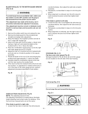
... square on the collar (5) underneath the table saw from the power source. 2. K) 5. K 900 (00) English 450 2 45° Stop 1. When the blade is 45° to the maximum bevel angle. 2. I Anti-kickback Pawl 8 10 9 Straight edge ADJUSTING THE 90°(00) AND 45° POSITIVE STOPS (FIG. Loosen the bevel lock knob, turn the blade tilting handwheel to move the blade to the table and tighten the blade bevel lock knob. 5. Loosen the mounting screw, position...
... square on the collar (5) underneath the table saw from the power source. 2. K) 5. K 900 (00) English 450 2 45° Stop 1. When the blade is 45° to the maximum bevel angle. 2. I Anti-kickback Pawl 8 10 9 Straight edge ADJUSTING THE 90°(00) AND 45° POSITIVE STOPS (FIG. Loosen the bevel lock knob, turn the blade tilting handwheel to move the blade to the table and tighten the blade bevel lock knob. 5. Loosen the mounting screw, position...
Instruction Manual
Page 14
... the rear of the miter gauge groove, perform adjustment procedure described in the square assembly. 7. This adjustment was made . 1. Remove the blade guard for the rip fence (2) and miter gauge (3) are located on the left side screw (2) clockwise. 5. Place the combination square base (1) into the right side miter gauge groove (2). (Fig.M) 6. The adjusting mechanism is achievde, turn the left screw (2) nutil it touches the pivot rod (4) then tighten both nuts (1). If the front...
... the rear of the miter gauge groove, perform adjustment procedure described in the square assembly. 7. This adjustment was made . 1. Remove the blade guard for the rip fence (2) and miter gauge (3) are located on the left side screw (2) clockwise. 5. Place the combination square base (1) into the right side miter gauge groove (2). (Fig.M) 6. The adjusting mechanism is achievde, turn the left screw (2) nutil it touches the pivot rod (4) then tighten both nuts (1). If the front...
Instruction Manual
Page 15
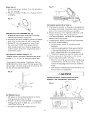
...-tightening the adjusting screw will slide freely through the table top grooves. 2. If adjustment is moved by using a combination square. If fence is loose when the handle is in a scrap piece of the saw table and engage the holding clamp (2) is 90º. Do not turn the adjusting screw more than 1/4 turn the adjusting nut (5) clockwise until it is fully extended. 2. S 5 1 3 RIP FENCE (FIG. Lift upward on the handle (2). • Hold the fence bracket...
...-tightening the adjusting screw will slide freely through the table top grooves. 2. If adjustment is moved by using a combination square. If fence is loose when the handle is in a scrap piece of the saw table and engage the holding clamp (2) is 90º. Do not turn the adjusting screw more than 1/4 turn the adjusting nut (5) clockwise until it is fully extended. 2. S 5 1 3 RIP FENCE (FIG. Lift upward on the handle (2). • Hold the fence bracket...
Instruction Manual
Page 16
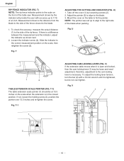
.... To adjust the locking lever tension, turn the bar (2) with accuracy up to align to the right side of the fence closest to 1/16 of the table saw. T ADJUSTING THE CUTTING LINE INDICATOR (FIG. T-1) The table extension scale pointer (1) should be loose and need adjustment, therefore, adjustment to the side of the rip fence. If not, loosen the holding screw (2), position the pointer over tighten. Slide the indicator...
.... To adjust the locking lever tension, turn the bar (2) with accuracy up to align to the right side of the fence closest to 1/16 of the table saw. T ADJUSTING THE CUTTING LINE INDICATOR (FIG. T-1) The table extension scale pointer (1) should be loose and need adjustment, therefore, adjustment to the side of the rip fence. If not, loosen the holding screw (2), position the pointer over tighten. Slide the indicator...
Instruction Manual
Page 17
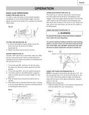
... the switch downward. 3. Release cam locking lever. 1. W) 1. If the motor stops during operation, turn the blade elevation handwheel (1) to the desired blade height, and then tighten the bevel lock handle (2) to the desired dimension using the scale on front rail for bevel cutting, loosen the bevel lock knob (2) and turn the saw with the fence to maintain the desired blade angle. If the switch key is removed while the saw is minimized and the saw . Z) NOTE: Use scale on rear rail. Tighten the bevel lock knob...
... the switch downward. 3. Release cam locking lever. 1. W) 1. If the motor stops during operation, turn the blade elevation handwheel (1) to the desired blade height, and then tighten the bevel lock handle (2) to the desired dimension using the scale on front rail for bevel cutting, loosen the bevel lock knob (2) and turn the saw with the fence to maintain the desired blade angle. If the switch key is removed while the saw is minimized and the saw . Z) NOTE: Use scale on rear rail. Tighten the bevel lock knob...
Instruction Manual
Page 18
... using the saw ON and wait for the blade to come to cause careless mistakes. The bevel angle lock knob is cutting either across the width or across the grain of the table. 10.Never pull the piece back when the blade is turning. If ripping, the fence is locked into the blade by pushing forward on the table and against the fence and must have a straight edge against the fence. Safety...
... using the saw ON and wait for the blade to come to cause careless mistakes. The bevel angle lock knob is cutting either across the width or across the grain of the table. 10.Never pull the piece back when the blade is turning. If ripping, the fence is locked into the blade by pushing forward on the table and against the fence and must have a straight edge against the fence. Safety...
Instruction Manual
Page 19
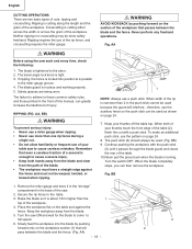
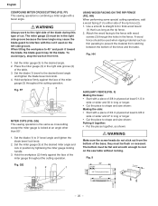
.... CROSSCUTTING (FIG. Start the saw to pull the workpiece backwards during this type of the blade during a cutting operation. Do not try to 1in. CC 1 3 2 USING WOOD FACING ON THE MITER GAUGE (Fig. WARNING Always work to a sawhorse. Adjust the blade (3) to rip small pieces. English BEVEL RIPPING This cut is the same as crosscutting except the blade is 1/8 in wide. 1. Turn the switch OFF, and carefully slide the workpiece out...
.... CROSSCUTTING (FIG. Start the saw to pull the workpiece backwards during this type of the blade during a cutting operation. Do not try to 1in. CC 1 3 2 USING WOOD FACING ON THE MITER GAUGE (Fig. WARNING Always work to a sawhorse. Adjust the blade (3) to rip small pieces. English BEVEL RIPPING This cut is the same as crosscutting except the blade is 1/8 in wide. 1. Turn the switch OFF, and carefully slide the workpiece out...
Instruction Manual
Page 20
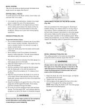
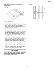
... tighten the blade bevel lock knob. 4. HH) When performing some special cutting operations, add a wood facing (1) to rest on the left side groove. The miter gauge (3) must be flush or recessed. The bottom must be used on the saw table without rocking. 3-1/2" Fig. GG 3 2 1 USING WOOD FACING ON THE RIP FENCE (FIG. Fig. FF) This sawing operation is as long as shown: WARNING Make sure the screw heads...
... tighten the blade bevel lock knob. 4. HH) When performing some special cutting operations, add a wood facing (1) to rest on the left side groove. The miter gauge (3) must be flush or recessed. The bottom must be used on the saw table without rocking. 3-1/2" Fig. GG 3 2 1 USING WOOD FACING ON THE RIP FENCE (FIG. Fig. FF) This sawing operation is as long as shown: WARNING Make sure the screw heads...
Instruction Manual
Page 21
Attach auxiliary fence to rip fence with the dado operation. - 21 - JJ) Fig. It will not strike the housing, insert, or motor when in or less. Use only the correct number of the cut to 1/2 in the dado set . 3. The arbor (1) on the arbor nut (3). Check saw restricts the maximum width of round outside flange (2) before screwing on this saw blade, original table inser and blade guard. The dado blade insert is packed with this...
Attach auxiliary fence to rip fence with the dado operation. - 21 - JJ) Fig. It will not strike the housing, insert, or motor when in or less. Use only the correct number of the cut to 1/2 in the dado set . 3. The arbor (1) on the arbor nut (3). Check saw restricts the maximum width of round outside flange (2) before screwing on this saw blade, original table inser and blade guard. The dado blade insert is packed with this...
Instruction Manual
Page 22
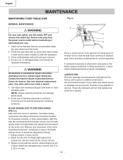
... blade raising screw (1) should be checked for service. English MAINTENANCE MAINTAINING YOUR TABLE SAW Fig. Remove the plug from the power source, turn the switch OFF and remove the switch key. These dry lubricants will not hold sawdust as follows: 1. Tighten nut (2) with pitch and gum remover. 4. If excessive looseness is 0.16 in place. BLADE RAISING AND TILTING MECHANISM (FIG. Observe any parts of the motor mounting mechanism. Use only identical replacement parts...
... blade raising screw (1) should be checked for service. English MAINTENANCE MAINTAINING YOUR TABLE SAW Fig. Remove the plug from the power source, turn the switch OFF and remove the switch key. These dry lubricants will not hold sawdust as follows: 1. Tighten nut (2) with pitch and gum remover. 4. If excessive looseness is 0.16 in place. BLADE RAISING AND TILTING MECHANISM (FIG. Observe any parts of the motor mounting mechanism. Use only identical replacement parts...
Instruction Manual
Page 23
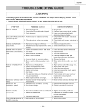
.... Install and use rip fence. 4. Dull blade. 5. Sawdust and dirt in . 1. Machine vibrates excessively. 1. Tighten all the way past saw it is past saw blade. Miter gauge out of adjustment. 1. Cord damaged. 3. Authorized Service Center. 1. Check blade with turpentine and coarse steel wool. 4. Material pinched blade 1. Replace blade. 2. Remove blade and clean with square and adjust to speed. 1. Incorrect blade for any reason the motor will not start , turn the switch OFF and always remove the plug from blade. 1. Change the blade...
.... Install and use rip fence. 4. Dull blade. 5. Sawdust and dirt in . 1. Machine vibrates excessively. 1. Tighten all the way past saw it is past saw blade. Miter gauge out of adjustment. 1. Cord damaged. 3. Authorized Service Center. 1. Check blade with turpentine and coarse steel wool. 4. Material pinched blade 1. Replace blade. 2. Remove blade and clean with square and adjust to speed. 1. Incorrect blade for any reason the motor will not start , turn the switch OFF and always remove the plug from blade. 1. Change the blade...

Instruction Manual
Page 69
... BAR 1 HANDLE 1 BEVEL ANGLE ADJUSTMENT ASS'Y 1 BLIND RIVET 6 ANGLE ROD 1 SPACER 1 MOVABLE COVER 1 FRONT COVER 1 MOTOR 1 RACK (FRONT) 1 RETAINING CLIP 1 SLEEVE-RUBBER 1 WARNING LABEL 1 CAUTION LABEL 1 CAUTION LABEL 1 BLADE GUARD ASS'Y 1 POWER CABLE ASS'Y 1 RIP FENCE ASS'Y 1 MITER GAUGE ASS'Y 1 HEIGHT REGULATING BOLT ASS'Y 1 SCALE 1 LABEL 1 LABEL 1 LABEL 1 RETAINING CLIP 1 COVER 1 COLLAR 2 BRACKET GROUP ASS'Y 1 SCALE ASS'Y 1 LABEL 1 - 69 - English PARTS LIST 10" JOBSITE TABLE SAW PARTS LIST FOR SCHEMATIC HKU...
... BAR 1 HANDLE 1 BEVEL ANGLE ADJUSTMENT ASS'Y 1 BLIND RIVET 6 ANGLE ROD 1 SPACER 1 MOVABLE COVER 1 FRONT COVER 1 MOTOR 1 RACK (FRONT) 1 RETAINING CLIP 1 SLEEVE-RUBBER 1 WARNING LABEL 1 CAUTION LABEL 1 CAUTION LABEL 1 BLADE GUARD ASS'Y 1 POWER CABLE ASS'Y 1 RIP FENCE ASS'Y 1 MITER GAUGE ASS'Y 1 HEIGHT REGULATING BOLT ASS'Y 1 SCALE 1 LABEL 1 LABEL 1 LABEL 1 RETAINING CLIP 1 COVER 1 COLLAR 2 BRACKET GROUP ASS'Y 1 SCALE ASS'Y 1 LABEL 1 - 69 - English PARTS LIST 10" JOBSITE TABLE SAW PARTS LIST FOR SCHEMATIC HKU...


