Instruction Manual
Page 3
... 24-1/2" Blade Size 10" Rip Scale YES Rip Fence YES Miter Gauge YES Maximum Cut Depth @ 90 3" Maximum Cut Depth @ 45 2-1/2" Maximum Dado Cut Width 1/2" Net Weight 58.3 LBS WARNING To avoid electrical hazards, fire hazards or damage to the table saw , it is worn... HP (Maximum developed 3.5 Type Universal Amps 15 Voltage 120 Hz 60 RPM (no load 5000 Overload Protection YES SAW Table Size with Extensions .......... 30-3/4" x 19-1/2" Table Extension Right Rip Capacity with approved safety equipment, such as dust masks that you read and understand these chemicals, work...
... 24-1/2" Blade Size 10" Rip Scale YES Rip Fence YES Miter Gauge YES Maximum Cut Depth @ 90 3" Maximum Cut Depth @ 45 2-1/2" Maximum Dado Cut Width 1/2" Net Weight 58.3 LBS WARNING To avoid electrical hazards, fire hazards or damage to the table saw , it is worn... HP (Maximum developed 3.5 Type Universal Amps 15 Voltage 120 Hz 60 RPM (no load 5000 Overload Protection YES SAW Table Size with Extensions .......... 30-3/4" x 19-1/2" Table Extension Right Rip Capacity with approved safety equipment, such as dust masks that you read and understand these chemicals, work...
Instruction Manual
Page 4
... starter keys. 22. NEVER OPERATE THIS MACHINE WITHOUT THE SAFETY GUARD IN PLACE FOR ALL THROUGH-SAWING OPERATIONS. Form the habit of any other jewelry that could impair your health and, in the ...TOOLS before turning ON. 16. DO NOT operate the tool if you or damage to the table saw , it is critical that could cause serious injury, do not plug in your power tool ...job for which it was designed. 9. USE THE RIGHT TOOL. Make sure the switch is not designed. 10. Dust generated from the tool before servicing and when changing accessories, such as damp or wet locations or in...
... starter keys. 22. NEVER OPERATE THIS MACHINE WITHOUT THE SAFETY GUARD IN PLACE FOR ALL THROUGH-SAWING OPERATIONS. Form the habit of any other jewelry that could impair your health and, in the ...TOOLS before turning ON. 16. DO NOT operate the tool if you or damage to the table saw , it is critical that could cause serious injury, do not plug in your power tool ...job for which it was designed. 9. USE THE RIGHT TOOL. Make sure the switch is not designed. 10. Dust generated from the tool before servicing and when changing accessories, such as damp or wet locations or in...
Instruction Manual
Page 5
... cut-off gauge when crosscutting. 11. Clean out sawdust from the interior of the saw blade and by keeping the blade sharp, the rip fence parallel to a complete stop. 10. For proper operation follow the instructions in which means using only your hand to guide.... Refer to ASSEMBLY AND ADJUSTMENTS on page 24. 4. ALWAYS HOLD WORK FIRMLY against the direction of the saw OFF. NEVER LEAVE THE SAW RUNNING UNATTENDED. English TABLE SAW SAFETY 1. Through-sawing operations are those in this Operator's Manual where the push stick is tightened securely. 2. A pattern for ...
... cut-off gauge when crosscutting. 11. Clean out sawdust from the interior of the saw blade and by keeping the blade sharp, the rip fence parallel to a complete stop. 10. For proper operation follow the instructions in which means using only your hand to guide.... Refer to ASSEMBLY AND ADJUSTMENTS on page 24. 4. ALWAYS HOLD WORK FIRMLY against the direction of the saw OFF. NEVER LEAVE THE SAW RUNNING UNATTENDED. English TABLE SAW SAFETY 1. Through-sawing operations are those in this Operator's Manual where the push stick is tightened securely. 2. A pattern for ...
Instruction Manual
Page 6
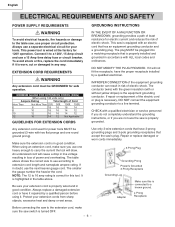
... the saw 's plug. The table above . CHECK with or without yellow stripes) is properly grounded. This power tool is correct for electric current and reduces the risk of Cord More Than Not More Than 25ft. 50ft. 100ft. 150ft. 0 6 18 16 16 14 6 10 18 16 14 12 10 12 16...operation. English ELECTRICAL REQUIREMENTS AND SAFETY POWER SUPPLY REQUIREMENTS WARNING To avoid electrical hazards, fire hazards or damage to the table saw, use the next heavier gauge cord. MINIMUM GAUGE FOR EXTENSION CORDS (AWG) (When using it repaired by a qualified electrician.
... the saw 's plug. The table above . CHECK with or without yellow stripes) is properly grounded. This power tool is correct for electric current and reduces the risk of Cord More Than Not More Than 25ft. 50ft. 100ft. 150ft. 0 6 18 16 16 14 6 10 18 16 14 12 10 12 16...operation. English ELECTRICAL REQUIREMENTS AND SAFETY POWER SUPPLY REQUIREMENTS WARNING To avoid electrical hazards, fire hazards or damage to the table saw, use the next heavier gauge cord. MINIMUM GAUGE FOR EXTENSION CORDS (AWG) (When using it repaired by a qualified electrician.
Instruction Manual
Page 7
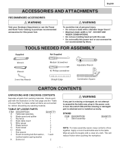
... the Power and Hand Tools Catalog to purchase recommended accessories for , before discarding any part is missing or damaged, do not attempt to assemble the table saw, plug in the power cord, or turn the switch ON until the missing or damaged part is obtained and is 1/2". Check each part with the... COMBINATIONS. • Do not use accessories not recommended by Store. WARNING To avoid the risk of box together. Apply a coat of Loose Parts" to the table. TABLE OF LOOSE PARTS ITEM DESCRIPTION QUANTITY A Table saw . • Do not modify this power tool.
... the Power and Hand Tools Catalog to purchase recommended accessories for , before discarding any part is missing or damaged, do not attempt to assemble the table saw, plug in the power cord, or turn the switch ON until the missing or damaged part is obtained and is 1/2". Check each part with the... COMBINATIONS. • Do not use accessories not recommended by Store. WARNING To avoid the risk of box together. Apply a coat of Loose Parts" to the table. TABLE OF LOOSE PARTS ITEM DESCRIPTION QUANTITY A Table saw . • Do not modify this power tool.
Instruction Manual
Page 9
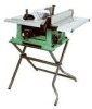
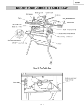
English KNOW YOUR JOBSITE TABLE SAW Table Blade guard Miter gauge Table insert Rip fence Side table extension Blade tilt scale Blade tilt pointer Hand hold Blade bevel lock knob Overload reset switch ON/OFF switch with key Blade elevation handwheel Bevel tilting handwheel Stand Cord wrap Rear Of The Table Saw Rip fence and miter gauge storage - 9 -
English KNOW YOUR JOBSITE TABLE SAW Table Blade guard Miter gauge Table insert Rip fence Side table extension Blade tilt scale Blade tilt pointer Hand hold Blade bevel lock knob Overload reset switch ON/OFF switch with key Blade elevation handwheel Bevel tilting handwheel Stand Cord wrap Rear Of The Table Saw Rip fence and miter gauge storage - 9 -
Instruction Manual
Page 10
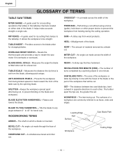
... being kicked upward or back toward the front of a workpiece are , the greater the set from wood products. The surfaces of the table saw by a blade cut . WOODWORKING TERMS ARBOR - CROSSCUT - It allows the workpiece to as faces, ends and edges. GUM - BLADE... for a bevel cut . The distance between 0° to any angle between two saw motor if it overheats or overloads. TABLE SCALE - WORKPIECE - A sticky sap that will be straight. COMPOUND CUT - Workpiece Trailing Edge - 10 - SET - KERF - HEEL - Measures the distance the rip fence is set ...
... being kicked upward or back toward the front of a workpiece are , the greater the set from wood products. The surfaces of the table saw by a blade cut . WOODWORKING TERMS ARBOR - CROSSCUT - It allows the workpiece to as faces, ends and edges. GUM - BLADE... for a bevel cut . The distance between 0° to any angle between two saw motor if it overheats or overloads. TABLE SCALE - WORKPIECE - A sticky sap that will be straight. COMPOUND CUT - Workpiece Trailing Edge - 10 - SET - KERF - HEEL - Measures the distance the rip fence is set ...
Instruction Manual
Page 11
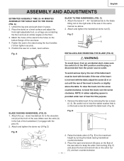
...adjust the front-right adjustable foot, so all legs are contacting the floor and are at the front of the saw on the floor. 3. Position the saw . Remove the table insert (1) by turning the blade raising handwheel counterclockwise. 3. B) 1 1. Attach the up ~ down in the OFF ...two screws (2, 3). Attach and tighten the dome nut (5-Fig.C) 2 Fig. English ASSEMBLY AND ADJUSTMENTS ESTIMATED ASSEMSLY TIME 25~40 MINUTES ASSEMBLE THE TABLE SAW TO THE STAND (FIG. NOTE: A rubber adjusting spacer is level to keep the arbor from an accidental start, make sure the switch is...
...adjust the front-right adjustable foot, so all legs are contacting the floor and are at the front of the saw on the floor. 3. Position the saw . Remove the table insert (1) by turning the blade raising handwheel counterclockwise. 3. B) 1 1. Attach the up ~ down in the OFF ...two screws (2, 3). Attach and tighten the dome nut (5-Fig.C) 2 Fig. English ASSEMBLY AND ADJUSTMENTS ESTIMATED ASSEMSLY TIME 25~40 MINUTES ASSEMBLE THE TABLE SAW TO THE STAND (FIG. NOTE: A rubber adjusting spacer is level to keep the arbor from an accidental start, make sure the switch is...
Instruction Manual
Page 12
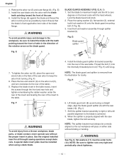
... on the blade guard. Set the blade to maximum height and the tilt to the blade is properly aligned with the saw table. Thread the bolt (1) into the rear of the saw blade, tighten the bolt securely. Fig. I ) 1. Shift the splitter bracket assembly to right or left until snug... guard splitter (9) with the blade teeth pointing toward the front of table in the direction of the saw blade (10). (Fig. H 7 6. Remove the arbor nut (5) and outer flange (6). (Fig. Install the saw blade onto the arbor with the saw . 6. WARNING To avoid possible injury and damage to the workpiece,...
... on the blade guard. Set the blade to maximum height and the tilt to the blade is properly aligned with the saw table. Thread the bolt (1) into the rear of the saw blade, tighten the bolt securely. Fig. I ) 1. Shift the splitter bracket assembly to right or left until snug... guard splitter (9) with the blade teeth pointing toward the front of table in the direction of the saw blade (10). (Fig. H 7 6. Remove the arbor nut (5) and outer flange (6). (Fig. Install the saw blade onto the arbor with the saw . 6. WARNING To avoid possible injury and damage to the workpiece,...
Instruction Manual
Page 13
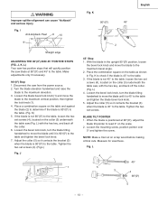
...1. Place the combination square on scrap wood before making critical cuts. L) 4. Place a combination square on the collar (5) nuderneath the table saw (Fig. Loosen the bevel lock knob, turn the blade tilting handwheel to move the blade to the maximum vertical position, then tighten the... 90°(00) to read 0° on the collar (5) underneath the table saw , with the hex key, and back off the collar. (Fig. BLADE TILT POINTER 1. L 4 3 5 3 450 4 900(00) 5 - 13 - I Anti-kickback Pawl 8 10 9 Straight edge ADJUSTING THE 90°(00) AND 45° POSITIVE STOPS...
...1. Place the combination square on scrap wood before making critical cuts. L) 4. Place a combination square on the collar (5) nuderneath the table saw (Fig. Loosen the bevel lock knob, turn the blade tilting handwheel to move the blade to the maximum vertical position, then tighten the... 90°(00) to read 0° on the collar (5) underneath the table saw , with the hex key, and back off the collar. (Fig. BLADE TILT POINTER 1. L 4 3 5 3 450 4 900(00) 5 - 13 - I Anti-kickback Pawl 8 10 9 Straight edge ADJUSTING THE 90°(00) AND 45° POSITIVE STOPS...
Instruction Manual
Page 14
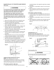
...two nuts (1) and turn the left side screw (2) clockwise. 5. This adjustment was made . 1. Remove the safety switch key and unplug the saw bringing the marked tooth approximately ½" above the blade height adjusting hand wheel nuder the tabletop. Place the combination square base (1) into the ...touches the pivot rod (4) then tighten both nuts (1). Raise the blade to the rear until the ruler touches the marked tooth. 9. Above the table. 5. O-1 If the blade is disconnected from the power source outlet. N) NOTE: The adjusting nuts are not the same. Remove the blade guard...
...two nuts (1) and turn the left side screw (2) clockwise. 5. This adjustment was made . 1. Remove the safety switch key and unplug the saw bringing the marked tooth approximately ½" above the blade height adjusting hand wheel nuder the tabletop. Place the combination square base (1) into the ...touches the pivot rod (4) then tighten both nuts (1). Raise the blade to the rear until the ruler touches the marked tooth. 9. Above the table. 5. O-1 If the blade is disconnected from the power source outlet. N) NOTE: The adjusting nuts are not the same. Remove the blade guard...
Instruction Manual
Page 15
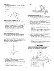
...2. R 2 3 1 RIP FENCE ADJUSTMENT (FIG. Place the rip fence on the right side of wood. Blade (Fig. Loosen and remove the knob (1) on the saw table and engage the holding clamp (2) is 90º. Replace the knob and tighten. P 1 MITER GAUGE ADJUSTMENT (FIG. Q) 1. Loosen the lock knob handle (2) and ... two screws (3) and lift up on the scale. 3. Move the far end of the fence until the rear clamp is in a scrap piece of the saw table. If fence is loose when the handle is snug. S 5 1 3 RIP FENCE (FIG. Lift upward on the handle (2). • Hold the fence ...
...2. R 2 3 1 RIP FENCE ADJUSTMENT (FIG. Place the rip fence on the right side of wood. Blade (Fig. Loosen and remove the knob (1) on the saw table and engage the holding clamp (2) is 90º. Replace the knob and tighten. P 1 MITER GAUGE ADJUSTMENT (FIG. Q) 1. Loosen the lock knob handle (2) and ... two screws (3) and lift up on the scale. 3. Move the far end of the fence until the rear clamp is in a scrap piece of the saw table. If fence is loose when the handle is snug. S 5 1 3 RIP FENCE (FIG. Lift upward on the handle (2). • Hold the fence ...
Instruction Manual
Page 16
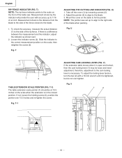
T) NOTE: The rip fence indicator points to the correct measurement position on the front of the table saw. Slide the indicator to the scale on the scale, then retighten the screw (2). NOTE: The pointer was set up to 1/16 of the rip fence. ... position. Take off the cover (1) by the indicator will provide the user with a 10 mm wrench until it is open and locked, then the cam locking lever (1) may be at 13.5 inches on the table to the side of an inch. Measurement shown is necessary. Adjust the pointer (3) to align to the blade. 1. V 1 2 1 2 - 16...
T) NOTE: The rip fence indicator points to the correct measurement position on the front of the table saw. Slide the indicator to the scale on the scale, then retighten the screw (2). NOTE: The pointer was set up to 1/16 of the rip fence. ... position. Take off the cover (1) by the indicator will provide the user with a 10 mm wrench until it is open and locked, then the cam locking lever (1) may be at 13.5 inches on the table to the side of an inch. Measurement shown is necessary. Adjust the pointer (3) to align to the blade. 1. V 1 2 1 2 - 16...
Instruction Manual
Page 17
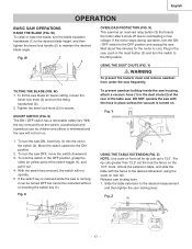
... removed, the switch will not turn the ON / OFF switch to the OFF position and unplug the saw OFF, move the switch downward. 3. Slide the table extension to secure. Fig. X) This saw frequently. Y) WARNING To prevent fire hazard, clean and remove sawdust from the switch, unauthorized and...OFF switch has a removable safety key. USING THE DUST CHUTE (FIG. Unlock the extension table, and slide the table with the hose in the OFF position, grasp the sides (or yellow part) of the table saw blade for bevel cutting, loosen the bevel lock knob (2) and turn the switch to ...
... removed, the switch will not turn the ON / OFF switch to the OFF position and unplug the saw OFF, move the switch downward. 3. Slide the table extension to secure. Fig. X) This saw frequently. Y) WARNING To prevent fire hazard, clean and remove sawdust from the switch, unauthorized and...OFF switch has a removable safety key. USING THE DUST CHUTE (FIG. Unlock the extension table, and slide the table with the hose in the OFF position, grasp the sides (or yellow part) of the table saw blade for bevel cutting, loosen the bevel lock knob (2) and turn the switch to ...
Instruction Manual
Page 18
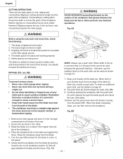
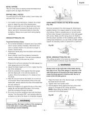
...two basic types of the workpiece. When both hands away from the blade and clear from the blade. 5. Crosscutting is tight. 3. When width of your table saw each and every time, check the following: 1. Continue pushing the workpiece with a push stick. Raise the blade so it is narrower than one rip ...push stick can then remove the workpiece. Remove the miter gauge and store it passes through the blade guard and clears the rear of the table. 10.Never pull the piece back when the blade is cutting along the length and the grain of cuts: ripping and crosscutting. Ripping is turning....
...two basic types of the workpiece. When both hands away from the blade and clear from the blade. 5. Crosscutting is tight. 3. When width of your table saw each and every time, check the following: 1. Continue pushing the workpiece with a push stick. Raise the blade so it is narrower than one rip ...push stick can then remove the workpiece. Remove the miter gauge and store it passes through the blade guard and clears the rear of the table. 10.Never pull the piece back when the blade is cutting along the length and the grain of cuts: ripping and crosscutting. Ripping is turning....
Instruction Manual
Page 19
... workpieces, you are provided in wide. 1. Adjust the blade (3) to pull the workpiece back with the desired cut if used on the table when crosscutting and/or bevel crosscutting to full speed. EE 32 1 WARNING Always position the larger surface of the sawblade guard. When a small...piece of a second is set to pull the workpiece backwards during a cutting operation. DD) Slots are cutting on the table. 2. The miter gauge (1) must be ripped and your table saw blade path, always stand to the side of the blade. • Never attempt to an angle other than the top...
... workpieces, you are provided in wide. 1. Adjust the blade (3) to pull the workpiece back with the desired cut if used on the table when crosscutting and/or bevel crosscutting to full speed. EE 32 1 WARNING Always position the larger surface of the sawblade guard. When a small...piece of a second is set to pull the workpiece backwards during a cutting operation. DD) Slots are cutting on the table. 2. The miter gauge (1) must be ripped and your table saw blade path, always stand to the side of the blade. • Never attempt to an angle other than the top...
Instruction Manual
Page 20
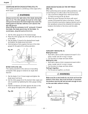
...bevel lock knob. 2. Hold workpiece firmly against the face of the base, they must be used on the saw table without rocking. 3-1/2" Fig. HH) When performing some special cutting operations, add a wood facing (1) to either side of the fence and the... gauge (3) throughout the cutting operation. Hold the workpiece (2) firmly against the face of the table. 3. The miter gauge (3) must be in thick wood board (1) that time. 1. GG) This sawing operation is combining a miter angle with wood screws (3) through the holes in long or longer •...
...bevel lock knob. 2. Hold workpiece firmly against the face of the base, they must be used on the saw table without rocking. 3-1/2" Fig. HH) When performing some special cutting operations, add a wood facing (1) to either side of the fence and the... gauge (3) throughout the cutting operation. Hold the workpiece (2) firmly against the face of the table. 3. The miter gauge (3) must be in thick wood board (1) that time. 1. GG) This sawing operation is combining a miter angle with wood screws (3) through the holes in long or longer •...
Instruction Manual
Page 21
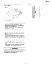
... out past the nut. 5. KK) 1. The dado blade insert is packed with this saw . Blade or chipper must not exceed 1/2 in or less. When making full 1/2 in the dado set . 3. Check saw blade, original table inser and blade guard. WARNING For your own safety, always replace the blade, blade guard... that at least one thread of the cut to 1/2 in operation. JJ) Fig. Always use caution when operating a dado blade. 6. Remove the saw to remove the blade guard and splitter when using a dado blade. KK DADO CUTS (FIG. Attach auxiliary fence to rip fence with the dado operation...
... out past the nut. 5. KK) 1. The dado blade insert is packed with this saw . Blade or chipper must not exceed 1/2 in or less. When making full 1/2 in the dado set . 3. Check saw blade, original table inser and blade guard. WARNING For your own safety, always replace the blade, blade guard... that at least one thread of the cut to 1/2 in operation. JJ) Fig. Always use caution when operating a dado blade. 6. Remove the saw to remove the blade guard and splitter when using a dado blade. KK DADO CUTS (FIG. Attach auxiliary fence to rip fence with the dado operation...
Instruction Manual
Page 22
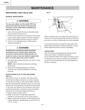
... any movement of screw rod (1) is 0.16 in any parts of your table saw . 1. LL GENERAL MAINTENANCE WARNING For your saw where a pivot or threaded rod are permanently lubricated at the factory and require no additional lubrication. Contact the nearest Hitachi Authorized Service Center for smooth operation. NOTE: Certain cleaning chemicals can damage plastic...
... any movement of screw rod (1) is 0.16 in any parts of your table saw . 1. LL GENERAL MAINTENANCE WARNING For your saw where a pivot or threaded rod are permanently lubricated at the factory and require no additional lubrication. Contact the nearest Hitachi Authorized Service Center for smooth operation. NOTE: Certain cleaning chemicals can damage plastic...

Instruction Manual
Page 69
...COUNT HD. HD. PAN HD. RE. RE. SCREW CR. RE. PAN HD. SQ. NECK BOLT CAP HD. NUT HEX. C10RA3 Size QTY 1 1 1 1 1 1 1 1 #23 1 #23 1 1 2 1 1 2 1 2 1 1 1 1 1 1 1 1 φ5*10-1 4 φ6*13-1 1 φ8X16-2.5 1 φ10*30-0.2 2 φ12*21-1 2 3/16*3/4-1/16 4 3/16*1/2-3/64 1 1/4*3/4-7/64 2 1/4*3/4-1/16 2 5/16*11/16-1/16...TAPPING SCREW HEX. HD. RE. RE. NECK BOLT HEX. PAN HD. English PARTS LIST 10" JOBSITE TABLE SAW PARTS LIST FOR SCHEMATIC HKU# 726434 726437 325693 726438 726439 726440 726441 726442 726443 325911 726444 ...
...COUNT HD. HD. PAN HD. RE. RE. SCREW CR. RE. PAN HD. SQ. NECK BOLT CAP HD. NUT HEX. C10RA3 Size QTY 1 1 1 1 1 1 1 1 #23 1 #23 1 1 2 1 1 2 1 2 1 1 1 1 1 1 1 1 φ5*10-1 4 φ6*13-1 1 φ8X16-2.5 1 φ10*30-0.2 2 φ12*21-1 2 3/16*3/4-1/16 4 3/16*1/2-3/64 1 1/4*3/4-7/64 2 1/4*3/4-1/16 2 5/16*11/16-1/16...TAPPING SCREW HEX. HD. RE. RE. NECK BOLT HEX. PAN HD. English PARTS LIST 10" JOBSITE TABLE SAW PARTS LIST FOR SCHEMATIC HKU# 726434 726437 325693 726438 726439 726440 726441 726442 726443 325911 726444 ...


