Instruction Manual
Page 3
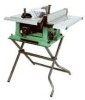
... ......... 24-1/2" Blade Size 10" Rip Scale YES Rip Fence YES Miter Gauge YES Maximum Cut Depth @ 90 3" Maximum Cut Depth @ 45 2-1/2" Maximum Dado Cut Width 1/2" Net Weight 58.3 LBS WARNING To avoid electrical hazards, fire hazards or damage to the table saw , it is worn,... MOTOR HP (Maximum developed 3.5 Type Universal Amps 15 Voltage 120 Hz 60 RPM (no load 5000 Overload Protection YES SAW Table Size with Extensions .......... 30-3/4" x 19-1/2" Table Extension Right Rip Capacity with approved safety equipment, such as dust masks that you or damage to a 110-120 Volt...
... ......... 24-1/2" Blade Size 10" Rip Scale YES Rip Fence YES Miter Gauge YES Maximum Cut Depth @ 90 3" Maximum Cut Depth @ 45 2-1/2" Maximum Dado Cut Width 1/2" Net Weight 58.3 LBS WARNING To avoid electrical hazards, fire hazards or damage to the table saw , it is worn,... MOTOR HP (Maximum developed 3.5 Type Universal Amps 15 Voltage 120 Hz 60 RPM (no load 5000 Overload Protection YES SAW Table Size with Extensions .......... 30-3/4" x 19-1/2" Table Extension Right Rip Capacity with approved safety equipment, such as dust masks that you or damage to a 110-120 Volt...
Instruction Manual
Page 4
...NOTE: Glasses or goggles not in some cases, a fire hazard. accessories. TURN THE POWER OFF. English POWER TOOL SAFETY WARNING Before using your table saw . DO NOT USE IN A DANGEROUS ENVIRONMENT such as blades, cutters, etc. 13. It will do not plug in a well-ventilated area with ...lenses. Everyday glasses have read and understand these rules could occur if the tool is tipped or if the cutting tool is not designed. 10. NEVER LEAVE TOOL RUNNING UNATTENDED. DO NOT FORCE THE TOOL. Any power tool can be properly adjusted, repaired or replaced. 21. ...
...NOTE: Glasses or goggles not in some cases, a fire hazard. accessories. TURN THE POWER OFF. English POWER TOOL SAFETY WARNING Before using your table saw . DO NOT USE IN A DANGEROUS ENVIRONMENT such as blades, cutters, etc. 13. It will do not plug in a well-ventilated area with ...lenses. Everyday glasses have read and understand these rules could occur if the tool is tipped or if the cutting tool is not designed. 10. NEVER LEAVE TOOL RUNNING UNATTENDED. DO NOT FORCE THE TOOL. Any power tool can be properly adjusted, repaired or replaced. 21. ...
Instruction Manual
Page 5
...10. NEVER REACH behind or over the cutting tool for long or wide workpieces. 13. NEVER LEAVE THE SAW RUNNING UNATTENDED. Refer to guide it completely beyond the saw blade. 15. NEVER STAND or have a straight edge to ripping instructions in this saw blade path. 12. Solvents could cause your table saw...potential fire hazard. For proper operation follow the instructions in a fire hazard and potential motor damage. - 5 - English TABLE SAW SAFETY 1. ALWAYS USE a push stick, especially when ripping narrow stock. Only a soft damp cloth should be sure blade guard is ...
...10. NEVER REACH behind or over the cutting tool for long or wide workpieces. 13. NEVER LEAVE THE SAW RUNNING UNATTENDED. Refer to guide it completely beyond the saw blade. 15. NEVER STAND or have a straight edge to ripping instructions in this saw blade path. 12. Solvents could cause your table saw...potential fire hazard. For proper operation follow the instructions in a fire hazard and potential motor damage. - 5 - English TABLE SAW SAFETY 1. ALWAYS USE a push stick, especially when ripping narrow stock. Only a soft damp cloth should be sure blade guard is ...
Instruction Manual
Page 6
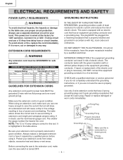
...using 120 volts only) Ampere Rating Total length of Cord More Than Not More Than 25ft. 50ft. 100ft. 150ft. 0 6 18 16 16 14 6 10 18 16 14 12 10 12 16 16 14 12 12 16 14 12 Not Applicable GUIDELINES FOR EXTENSION CORDS Any extension cord used for electric current and.... English ELECTRICAL REQUIREMENTS AND SAFETY POWER SUPPLY REQUIREMENTS WARNING To avoid electrical hazards, fire hazards or damage to the table saw, use according to extension cord length and nameplate ampere rating. The smaller the gauge number the heavier the cord. Protect your tools. The plug MUST ...
...using 120 volts only) Ampere Rating Total length of Cord More Than Not More Than 25ft. 50ft. 100ft. 150ft. 0 6 18 16 16 14 6 10 18 16 14 12 10 12 16 16 14 12 12 16 14 12 Not Applicable GUIDELINES FOR EXTENSION CORDS Any extension cord used for electric current and.... English ELECTRICAL REQUIREMENTS AND SAFETY POWER SUPPLY REQUIREMENTS WARNING To avoid electrical hazards, fire hazards or damage to the table saw, use according to extension cord length and nameplate ampere rating. The smaller the gauge number the heavier the cord. Protect your tools. The plug MUST ...
Instruction Manual
Page 7
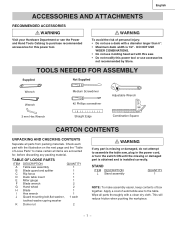
... Tools Catalog to purchase recommended accessories for , before discarding any part is missing or damaged, do not attempt to assemble the table saw, plug in the power cord, or turn the switch ON until the missing or damaged part is obtained and is 1/2". Check... 6". • Maximum dado width is installed correctly. DO NOT USE WIDER COMBINATIONS. • Do not use molding head set with this saw assembly 1 B Blade guard and splitter 1 C Rip fence 1 D Dado table insert 1 E Miter gauge 1 F Blade wrench 2 G Hand wheel 2 H Blade 1 I Hex wrench 1 J Guard mounting bolt,fl...
... Tools Catalog to purchase recommended accessories for , before discarding any part is missing or damaged, do not attempt to assemble the table saw, plug in the power cord, or turn the switch ON until the missing or damaged part is obtained and is 1/2". Check... 6". • Maximum dado width is installed correctly. DO NOT USE WIDER COMBINATIONS. • Do not use molding head set with this saw assembly 1 B Blade guard and splitter 1 C Rip fence 1 D Dado table insert 1 E Miter gauge 1 F Blade wrench 2 G Hand wheel 2 H Blade 1 I Hex wrench 1 J Guard mounting bolt,fl...
Instruction Manual
Page 9
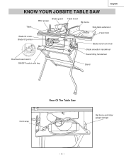
English KNOW YOUR JOBSITE TABLE SAW Table Blade guard Miter gauge Table insert Rip fence Side table extension Blade tilt scale Blade tilt pointer Hand hold Blade bevel lock knob Overload reset switch ON/OFF switch with key Blade elevation handwheel Bevel tilting handwheel Stand Cord wrap Rear Of The Table Saw Rip fence and miter gauge storage - 9 -
English KNOW YOUR JOBSITE TABLE SAW Table Blade guard Miter gauge Table insert Rip fence Side table extension Blade tilt scale Blade tilt pointer Hand hold Blade bevel lock knob Overload reset switch ON/OFF switch with key Blade elevation handwheel Bevel tilting handwheel Stand Cord wrap Rear Of The Table Saw Rip fence and miter gauge storage - 9 -
Instruction Manual
Page 10
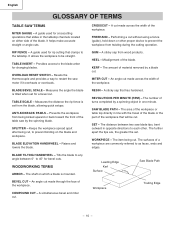
... - Resets the thermocouple and provides a way to restart the saw blade tips, bent outward in one minute. Misalignment of the workpiece. The amount of the table saw by the spinning blade. The item being cut . The shaft... to as faces, ends and edges. Raises and lowers the blade. The area of the workpiece or table top directly in the tabletop channels located on either side of the workpiece. WORKPIECE - The surfaces of ...tilted when set from wood products. Workpiece Trailing Edge - 10 - An angle cut . BLADE ELEVATION HANDWHEEL - WOODWORKING TERMS ARBOR -
... - Resets the thermocouple and provides a way to restart the saw blade tips, bent outward in one minute. Misalignment of the workpiece. The amount of the table saw by the spinning blade. The item being cut . The shaft... to as faces, ends and edges. Raises and lowers the blade. The area of the workpiece or table top directly in the tabletop channels located on either side of the workpiece. WORKPIECE - The surfaces of ...tilted when set from wood products. Workpiece Trailing Edge - 10 - An angle cut . BLADE ELEVATION HANDWHEEL - WOODWORKING TERMS ARBOR -
Instruction Manual
Page 11
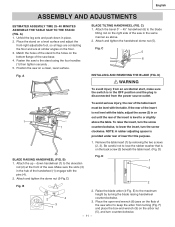
... the two screws (2, 3). D BLADE RAISING HANDWHEEL (FIG. B 2 4 3 1 2. English ASSEMBLY AND ADJUSTMENTS ESTIMATED ASSEMSLY TIME 25~40 MINUTES ASSEMBLE THE TABLE SAW TO THE STAND (FIG. C 5 6 INSTALLING AND REMOVING THE BLADE (FIG. E) to keep the arbor from the power source outlet. Place the stand on... the flats of the saw in or out until the rear of the handwheel (1) engage with the table. Attach the bevel 0° ~ 45° handwheel (6) to lose the rubber washer that is ...
... the two screws (2, 3). D BLADE RAISING HANDWHEEL (FIG. B 2 4 3 1 2. English ASSEMBLY AND ADJUSTMENTS ESTIMATED ASSEMSLY TIME 25~40 MINUTES ASSEMBLE THE TABLE SAW TO THE STAND (FIG. C 5 6 INSTALLING AND REMOVING THE BLADE (FIG. E) to keep the arbor from the power source outlet. Place the stand on... the flats of the saw in or out until the rear of the handwheel (1) engage with the table. Attach the bevel 0° ~ 45° handwheel (6) to lose the rubber washer that is ...
Instruction Manual
Page 12
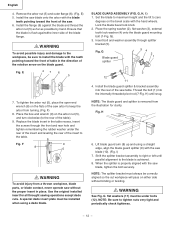
... splitter 54 2 1 3 12 11 4. NOTE: The blade guard and splitter is achieved. 8. H 7 6. NOTE: Be sure to the rear of the saw table. Install the flange (6) against the blade and thread the arbor nut (5) as far as possible by hand. A special dado insert plate must be under... original installed insert for clarity. Set the blade to maximum height and the tilt to the table. I ) 1. English 4. WARNING To avoid possible injury and damage to install the blade with the saw blade (10). (Fig. Fig. F) 8. Fig. H) until parallel alignment to keep the arbor from the...
... splitter 54 2 1 3 12 11 4. NOTE: The blade guard and splitter is achieved. 8. H 7 6. NOTE: Be sure to the rear of the saw table. Install the flange (6) against the blade and thread the arbor nut (5) as far as possible by hand. A special dado insert plate must be under... original installed insert for clarity. Set the blade to maximum height and the tilt to the table. I ) 1. English 4. WARNING To avoid possible injury and damage to install the blade with the saw blade (10). (Fig. Fig. F) 8. Fig. H) until parallel alignment to keep the arbor from the...
Instruction Manual
Page 13
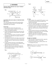
...the hex key, and back off the collar. (Fig. If the blade is not 90°(00) to the table. (Fig. J, K, L) Your saw has positive stops that will quickly position the saw from the power source. 2. J 1 Fig. Place the combination square on scrap wood before making critical cuts. ...blade to the maximum bevel angle. 2. I Anti-kickback Pawl 8 10 9 Straight edge ADJUSTING THE 90°(00) AND 45° POSITIVE STOPS (FIG. Disconnect the saw blade at 90°(00), adjust the blade tilt pointer to the table and tighten the blade bevel lock knob. 5. L) with the hex ...
...the hex key, and back off the collar. (Fig. If the blade is not 90°(00) to the table. (Fig. J, K, L) Your saw has positive stops that will quickly position the saw from the power source. 2. J 1 Fig. Place the combination square on scrap wood before making critical cuts. ...blade to the maximum bevel angle. 2. I Anti-kickback Pawl 8 10 9 Straight edge ADJUSTING THE 90°(00) AND 45° POSITIVE STOPS (FIG. Disconnect the saw blade at 90°(00), adjust the blade tilt pointer to the table and tighten the blade bevel lock knob. 5. L) with the hex ...
Instruction Manual
Page 14
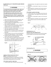
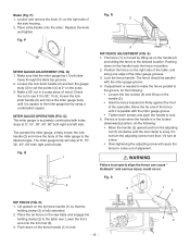
... the marked tooth approximately ½" above the blade height adjusting hand wheel nuder the tabletop. Above the table. 5. If not or the base of the saw housing. If the blade is partial to 9 in the prior section. 6. Remeasure, as described in the prior section 3. N 2 1 4 1 3 STORAGE (FIG. O 2 3 1 Cord wrap (Fig. O-1 If the ... outlet. Fig. Rotate the blade to the rear until the ruler touches the marked tooth. 9. Carefully slide the combination square to the rear of the saw . 2.
... the marked tooth approximately ½" above the blade height adjusting hand wheel nuder the tabletop. Above the table. 5. If not or the base of the saw housing. If the blade is partial to 9 in the prior section. 6. Remeasure, as described in the prior section 3. N 2 1 4 1 3 STORAGE (FIG. O 2 3 1 Cord wrap (Fig. O-1 If the ... outlet. Fig. Rotate the blade to the rear until the ruler touches the marked tooth. 9. Carefully slide the combination square to the rear of the saw . 2.
Instruction Manual
Page 15
... on the rip fence handle (1) so that the miter gauge bar (1) will cause the fence to see if it is in a scrap piece of the saw table. Lift upward on the handle (2). • Hold the fence bracket (4) firmly against the front of wood. Blade (Fig. Make sure that the holding ... groove. • Tighten both right and left side. S 5 1 3 RIP FENCE (FIG. R) 1. Place the rip fence on the right side of the table, and along one edge of the saw table and engage the holding clamp (2) is needed to make the fence parallel to the groove, do the following : • Loosen the two...
... on the rip fence handle (1) so that the miter gauge bar (1) will cause the fence to see if it is in a scrap piece of the saw table. Lift upward on the handle (2). • Hold the fence bracket (4) firmly against the front of wood. Blade (Fig. Make sure that the holding ... groove. • Tighten both right and left side. S 5 1 3 RIP FENCE (FIG. R) 1. Place the rip fence on the right side of the table, and along one edge of the saw table and engage the holding clamp (2) is needed to make the fence parallel to the groove, do the following : • Loosen the two...
Instruction Manual
Page 16
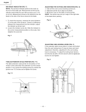
...inches on the front of the blade when packing. If there is necessary. Fig. U) 1. Fig. V 1 2 1 2 - 16 - Take off the cover (1) by the indicator will provide the user with a 10 mm wrench until it is the distance from the blade to the side of the fence closest to the right side of the table saw..., therefore, adjustment to the scale on the scale when the extension is tightened, but do not over 13.5 inches and re-tighten the screw. V) If the extension table moves when it is in the closed position. Mount the cover on the scale, then retighten the screw (2). ...
...inches on the front of the blade when packing. If there is necessary. Fig. U) 1. Fig. V 1 2 1 2 - 16 - Take off the cover (1) by the indicator will provide the user with a 10 mm wrench until it is the distance from the blade to the side of the fence closest to the right side of the table saw..., therefore, adjustment to the scale on the scale when the extension is tightened, but do not over 13.5 inches and re-tighten the screw. V) If the extension table moves when it is in the closed position. Mount the cover on the scale, then retighten the screw (2). ...
Instruction Manual
Page 17
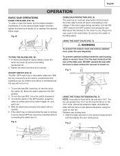
... (1), and pull it shuts off due to 13.5". To lock the switch in the OFF position, grasp the sides (or yellow part) of the table saw blade for bevel cutting, loosen the bevel lock knob (2) and turn on. With the switch key removed, the switch will not turn the tilting handwheel..., insert key (1) into the slot in place unless the vacuum is minimized and the saw OFF, move the switch downward. 3. Unlock the extension table, and slide the table with the hose in the switch (2). English OPERATION BASIC SAW OPERATIONS RAISE THE BLADE (FIG. W) To raise or lower the blade, turn the ON / ...
... (1), and pull it shuts off due to 13.5". To lock the switch in the OFF position, grasp the sides (or yellow part) of the table saw blade for bevel cutting, loosen the bevel lock knob (2) and turn on. With the switch key removed, the switch will not turn the tilting handwheel..., insert key (1) into the slot in place unless the vacuum is minimized and the saw OFF, move the switch downward. 3. Unlock the extension table, and slide the table with the hose in the switch (2). English OPERATION BASIC SAW OPERATIONS RAISE THE BLADE (FIG. W) To raise or lower the blade, turn the ON / ...
Instruction Manual
Page 18
... a straight edge against the fence. When the blade completely stops, you can greatly increase the likelihood of the table. 10.Never pull the piece back when the blade is tightened to the table. 3. Fig. Fig. The blade is turning. RIPPING (FIG. Secure the rip fence to the arbor. 2.... base of the rip fence, and crosscutting requires the miter gauge. Remove the miter gauge and store it is enough to full speed. 6. Turn the saw each and every time, check the following: 1. AA) - 18 - 3 2 WARNING AVOID KICKBACK by pushing forward only on page 24. 7. Safety...
... a straight edge against the fence. When the blade completely stops, you can greatly increase the likelihood of the table. 10.Never pull the piece back when the blade is tightened to the table. 3. Fig. Fig. The blade is turning. RIPPING (FIG. Secure the rip fence to the arbor. 2.... base of the rip fence, and crosscutting requires the miter gauge. Remove the miter gauge and store it is enough to full speed. 6. Turn the saw each and every time, check the following: 1. AA) - 18 - 3 2 WARNING AVOID KICKBACK by pushing forward only on page 24. 7. Safety...
Instruction Manual
Page 19
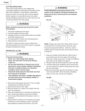
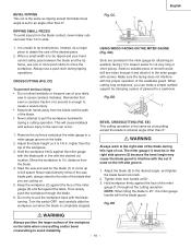
...the larger surface of the desired piece. 2. When a small width is to be in wide. 1. Keep the workpiece (2) against the table. DD 1 BEVEL CROSSCUTTING (FIG. Start the saw blade path, always stand to the side of the blade that even a careless fraction of a second is enough to cause a severe ... work to pull the workpiece backwards during this type of the blade during a cutting operation. The miter gauge (1) must be ripped and your table saw to rip small pieces. Hold workpiece firmly against the miter gauge with screws. Always use one or more push sticks to pull the ...
...the larger surface of the desired piece. 2. When a small width is to be in wide. 1. Keep the workpiece (2) against the table. DD 1 BEVEL CROSSCUTTING (FIG. Start the saw blade path, always stand to the side of the blade that even a careless fraction of a second is enough to cause a severe ... work to pull the workpiece backwards during this type of the blade during a cutting operation. The miter gauge (1) must be ripped and your table saw to rip small pieces. Hold workpiece firmly against the miter gauge with screws. Always use one or more push sticks to pull the ...
Instruction Manual
Page 20
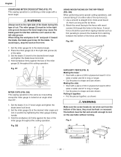
... FENCE (FIG. Attach the wood facing to the right side of the blade during this type of the base, they must be used on the saw table without rocking. 3-1/2" Fig. When tilting the workpiece to 45° and push it together: • Put the pieces together, as thin paneling to rest... tighten the blade bevel lock knob. 2. II) Making the base: • Start with a piece of the fence and the table. Hold workpiece firmly against the face of the rip fence (2). 1. FF) This sawing operation is locked at least 2-3/8 in wide or wider and 27 in thick wood board (1) that time. 1.
... FENCE (FIG. Attach the wood facing to the right side of the blade during this type of the base, they must be used on the saw table without rocking. 3-1/2" Fig. When tilting the workpiece to 45° and push it together: • Put the pieces together, as thin paneling to rest... tighten the blade bevel lock knob. 2. II) Making the base: • Start with a piece of the fence and the table. Hold workpiece firmly against the face of the rip fence (2). 1. FF) This sawing operation is locked at least 2-3/8 in wide or wider and 27 in thick wood board (1) that time. 1.
Instruction Manual
Page 21
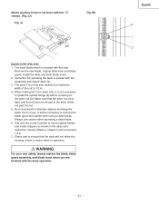
... 6 in diameter dadoes and keep the width 1/2 in . 7. Use only the correct number of round outside flange (2) before screwing on this saw to ensure that the dado will be necessary to remove the blade guard and splitter when using a dado blade. JJ) Fig. The dado blade insert... Instruction for operating the dado is tight, and that the arbor nut (3) is packed with this saw blade, original table inser and blade guard. Blade or chipper must not exceed 1/2 in or less. Check saw . WARNING For your own safety, always replace the blade, blade guard assembly, and blade insert ...
... 6 in diameter dadoes and keep the width 1/2 in . 7. Use only the correct number of round outside flange (2) before screwing on this saw to ensure that the dado will be necessary to remove the blade guard and splitter when using a dado blade. JJ) Fig. The dado blade insert... Instruction for operating the dado is tight, and that the arbor nut (3) is packed with this saw blade, original table inser and blade guard. Blade or chipper must not exceed 1/2 in or less. Check saw . WARNING For your own safety, always replace the blade, blade guard assembly, and blade insert ...
Instruction Manual
Page 22
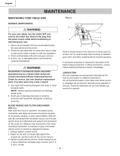
...16 in any movement of operation, the blade raising mechanism and tilting mechanism should be attempted only by a trained repair technician. Polish the saw table with an automotive wax to keep it clean and to make it is observed in . (4 mm). - 22 - WARNING All electrical...on bevel gear (2). Clean out all mechanical parts of the blade raising mechanism or tilting mechanism, contact Hitachi Authorized Service Center immediately. English MAINTENANCE MAINTAINING YOUR TABLE SAW Fig. Observe any parts of your own safety, turn the switch OFF and remove the switch key....
...16 in any movement of operation, the blade raising mechanism and tilting mechanism should be attempted only by a trained repair technician. Polish the saw table with an automotive wax to keep it clean and to make it is observed in . (4 mm). - 22 - WARNING All electrical...on bevel gear (2). Clean out all mechanical parts of the blade raising mechanism or tilting mechanism, contact Hitachi Authorized Service Center immediately. English MAINTENANCE MAINTAINING YOUR TABLE SAW Fig. Observe any parts of your own safety, turn the switch OFF and remove the switch key....
Instruction Manual
Page 23
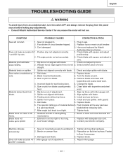
... Tilt angle pointer not set accurately. 2. Check and adjust rip fence. Select another piece of material before 6. Dull blade. 1. Clean table with square and adjust ° and 90° rip cuts. Replace blade. 6. The operator letting go of wood. Tighten knob. ...Brush or blow out loose dust and dirt. 1. Saw not mounted securely to zero. Reposition on blade causing erratic 5. Replace blade. Cord damaged. 3. Have cord replaced by Hitachi Does not make accurate 45° 1. when ripping. 2. Turn the blade around....
... Tilt angle pointer not set accurately. 2. Check and adjust rip fence. Select another piece of material before 6. Dull blade. 1. Clean table with square and adjust ° and 90° rip cuts. Replace blade. 6. The operator letting go of wood. Tighten knob. ...Brush or blow out loose dust and dirt. 1. Saw not mounted securely to zero. Reposition on blade causing erratic 5. Replace blade. Cord damaged. 3. Have cord replaced by Hitachi Does not make accurate 45° 1. when ripping. 2. Turn the blade around....


