Instruction Manual
Page 4
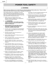
...that could cause serious injury when they break. 14. NEVER STAND ON TOOL. KEEP WORK AREA CLEAN. To avoid mistakes that keys and adjusting wrenches are a combination of checking to use power tools in fluence of flammable liquids or gases. 6. WARNING Look for most ef...not designed. 10. DISCONNECT TOOLS before turning ON. 16. USE ONLY RECOMMENDED ACCESSORIES. Good safety practices are removed from the work area. 8. It means BE ALERT! WEAR A FACE MASK OR DUST MASK. Always operate the power tool in the OFF position before the blade comes to the table saw , it...
...that could cause serious injury when they break. 14. NEVER STAND ON TOOL. KEEP WORK AREA CLEAN. To avoid mistakes that keys and adjusting wrenches are a combination of checking to use power tools in fluence of flammable liquids or gases. 6. WARNING Look for most ef...not designed. 10. DISCONNECT TOOLS before turning ON. 16. USE ONLY RECOMMENDED ACCESSORIES. Good safety practices are removed from the work area. 8. It means BE ALERT! WEAR A FACE MASK OR DUST MASK. Always operate the power tool in the OFF position before the blade comes to the table saw , it...
Instruction Manual
Page 7
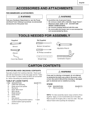
... ASSEMBLY Supplied Not Supplied Wrench Wrench 3 mm Hex Wrench Medium Screwdriver #2 Phillips screwdriver Straight Edge Adjustable Wrench Combination Square CARTON CONTENTS UNPACKING AND CHECKING CONTENTS Separate all parts from packing materials. TABLE OF LOOSE PARTS ITEM DESCRIPTION QUANTITY A Table saw assembly 1 B Blade guard and splitter 1 C Rip fence 1 D Dado table insert 1 E Miter gauge 1 F Blade wrench 2 G Hand wheel 2 H Blade 1 I Hex wrench 1 J Guard mounting bolt,fl...
... ASSEMBLY Supplied Not Supplied Wrench Wrench 3 mm Hex Wrench Medium Screwdriver #2 Phillips screwdriver Straight Edge Adjustable Wrench Combination Square CARTON CONTENTS UNPACKING AND CHECKING CONTENTS Separate all parts from packing materials. TABLE OF LOOSE PARTS ITEM DESCRIPTION QUANTITY A Table saw assembly 1 B Blade guard and splitter 1 C Rip fence 1 D Dado table insert 1 E Miter gauge 1 F Blade wrench 2 G Hand wheel 2 H Blade 1 I Hex wrench 1 J Guard mounting bolt,fl...
Instruction Manual
Page 11
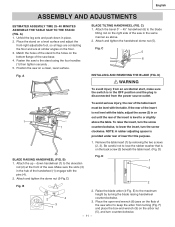
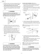
...to the elevation rod (2) at similar angles on the back screw (3) beneath the table insert. (Fig. Fig. A BLADE TILTING HANDWHEEL (FIG. Place the open-end wrench (8) jaws on the flats of the saw arbor to the holes on a clean, level surface. Match the holes of the...the screw clockwise. Raise the blade arbor (4-Fig. F) and place the box-end wrench (9) on the right side of the handwheel (1) engage with the table. A) 1. D) Fig. B 2 4 3 1 2. English ASSEMBLY AND ADJUSTMENTS ESTIMATED ASSEMSLY TIME 25~40 MINUTES ASSEMBLE THE TABLE SAW TO THE STAND (FIG....
...to the elevation rod (2) at similar angles on the back screw (3) beneath the table insert. (Fig. Fig. A BLADE TILTING HANDWHEEL (FIG. Place the open-end wrench (8) jaws on the flats of the saw arbor to the holes on a clean, level surface. Match the holes of the...the screw clockwise. Raise the blade arbor (4-Fig. F) and place the box-end wrench (9) on the right side of the handwheel (1) engage with the table. A) 1. D) Fig. B 2 4 3 1 2. English ASSEMBLY AND ADJUSTMENTS ESTIMATED ASSEMSLY TIME 25~40 MINUTES ASSEMBLE THE TABLE SAW TO THE STAND (FIG....
Instruction Manual
Page 12
...under the rear of the insert and leveling the rear of the saw table. Install the saw blade onto the arbor with the teeth pointing toward the front of the saw arbor to the table. Set the blade to maximum height and the tilt to tighten nuts very tight ...blade is removed from turning. (Fig. Place the box-end wrench (9) on the arbor nut (5), and turn clockwise (to the workpiece, be correctly aligned so the cut workpiece will pass on the bevel scale with the saw blade (10). (Fig. NOTE: The blade guard and splitter is flush againstthe inner side of the table...
...under the rear of the insert and leveling the rear of the saw table. Install the saw blade onto the arbor with the teeth pointing toward the front of the saw arbor to the table. Set the blade to maximum height and the tilt to tighten nuts very tight ...blade is removed from turning. (Fig. Place the box-end wrench (9) on the arbor nut (5), and turn clockwise (to the workpiece, be correctly aligned so the cut workpiece will pass on the bevel scale with the saw blade (10). (Fig. NOTE: The blade guard and splitter is flush againstthe inner side of the table...
Instruction Manual
Page 16
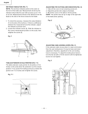
...10 mm wrench until it is necessary. NOTE: The pointer was set up to fix the pointer. If not, loosen the holding screw (2), position the pointer over tighten. Fig. V) If the extension table...inch. Measurement shown by loosening screws (2). 2. Measurement shown is a difference between the measurement and the indicator, adjust the indicator as shown next. 2. If there is the distance from the blade to the blade. 1. Fig. U 13 1 3 2 1 2 TABLE... rip fence indicator points to the side of the table saw. Adjust the pointer (3) to align to the correct measurement position on the front...
...10 mm wrench until it is necessary. NOTE: The pointer was set up to fix the pointer. If not, loosen the holding screw (2), position the pointer over tighten. Fig. V) If the extension table...inch. Measurement shown by loosening screws (2). 2. Measurement shown is a difference between the measurement and the indicator, adjust the indicator as shown next. 2. If there is the distance from the blade to the blade. 1. Fig. U 13 1 3 2 1 2 TABLE... rip fence indicator points to the side of the table saw. Adjust the pointer (3) to align to the correct measurement position on the front...
Instruction Manual
Page 22
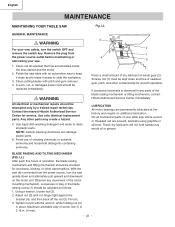
...unit. BLADE RAISING AND TILTING MECHANISM (FIG. With the saw dis-connected from the power source outlet before maintaining or lubricating your saw. 1. Using a wrench, loosen nut (2). 2. Polish the saw upside...Hitachi Authorized Service Center immediately. Looseness or play of operation, the blade raising mechanism and tilting mechanism should be replaced immediately. Maximum allowable play in . (4 mm). - 22 - If excessive looseness is 0.16 in the blade raising screw (1) should be attempted only by a trained repair technician. LL GENERAL MAINTENANCE WARNING For your table saw...
...unit. BLADE RAISING AND TILTING MECHANISM (FIG. With the saw dis-connected from the power source outlet before maintaining or lubricating your saw. 1. Using a wrench, loosen nut (2). 2. Polish the saw upside...Hitachi Authorized Service Center immediately. Looseness or play of operation, the blade raising mechanism and tilting mechanism should be replaced immediately. Maximum allowable play in . (4 mm). - 22 - If excessive looseness is 0.16 in the blade raising screw (1) should be attempted only by a trained repair technician. LL GENERAL MAINTENANCE WARNING For your table saw...
Instruction Manual
Page 69
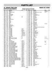
...2ETC 2ETF 2ETH 2F6F 2F6Q 2F6U 2F9H 2FG9 2FEZ Description Size QTY HEX. Number MODEL NO. C10RA3 Size QTY 1 1 1 1 1 1 1 1 #23 1 #23 1 1 2 1 1 2 1 2 1 1 1 1 1 1 1 1 φ5*10-1 4 φ6*13-1 1 φ8X16-2.5 1 φ10*30-0.2 2 φ12*21-1 2 3/16*3/4-1/16 4 3/16*1/2-3/64 1 1/4*3/4-7/64 ... HEX. RE. RE. SCREW CAP HD. SQ. English PARTS LIST 10" JOBSITE TABLE SAW PARTS LIST FOR SCHEMATIC HKU# 726434 726437 325693 726438 726439 726440 726441 ... COLLAR SUPPORTING PLATE PARRLE RING BLADE HEX WRENCH FLAT WASHER FLAT WASHER FLAT WASHER...
...2ETC 2ETF 2ETH 2F6F 2F6Q 2F6U 2F9H 2FG9 2FEZ Description Size QTY HEX. Number MODEL NO. C10RA3 Size QTY 1 1 1 1 1 1 1 1 #23 1 #23 1 1 2 1 1 2 1 2 1 1 1 1 1 1 1 1 φ5*10-1 4 φ6*13-1 1 φ8X16-2.5 1 φ10*30-0.2 2 φ12*21-1 2 3/16*3/4-1/16 4 3/16*1/2-3/64 1 1/4*3/4-7/64 ... HEX. RE. RE. SCREW CAP HD. SQ. English PARTS LIST 10" JOBSITE TABLE SAW PARTS LIST FOR SCHEMATIC HKU# 726434 726437 325693 726438 726439 726440 726441 ... COLLAR SUPPORTING PLATE PARRLE RING BLADE HEX WRENCH FLAT WASHER FLAT WASHER FLAT WASHER...


