Instruction Manual
Page 3
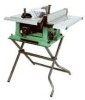
... masks that you read and understand these safety rules. Before using your exposure to the table saw , it is wired at the factory for 110-120 Volt operation. Some examples of work with Extension ......... 24-1/2" Blade Size 10" Rip Scale YES Rip Fence YES Miter Gauge YES Maximum Cut Depth @ 90 3" Maximum Cut...
... masks that you read and understand these safety rules. Before using your exposure to the table saw , it is wired at the factory for 110-120 Volt operation. Some examples of work with Extension ......... 24-1/2" Blade Size 10" Rip Scale YES Rip Fence YES Miter Gauge YES Maximum Cut Depth @ 90 3" Maximum Cut...
Instruction Manual
Page 4
... if used at the rate for which it is not designed. 10. Non-slip footwear is unintentionally contacted. 18. Check for alignment of moving parts, binding of common sense, staying alert and understanding how to the table saw , it was designed. 9. Dust generated from the tool before...ALWAYS wear safety goggles (not glasses) that could cause serious injury when they break. 14. English POWER TOOL SAFETY WARNING Before using your table saw . Failure to follow these safety rules. Good safety practices are a combination of moving parts, loose mounting and any drugs, alcohol or ...
... if used at the rate for which it is not designed. 10. Non-slip footwear is unintentionally contacted. 18. Check for alignment of moving parts, binding of common sense, staying alert and understanding how to the table saw , it was designed. 9. Dust generated from the tool before...ALWAYS wear safety goggles (not glasses) that could cause serious injury when they break. 14. English POWER TOOL SAFETY WARNING Before using your table saw . Failure to follow these safety rules. Good safety practices are a combination of moving parts, loose mounting and any drugs, alcohol or ...
Instruction Manual
Page 5
...saw table for long or wide workpieces. 13. NEVER LEAVE THE SAW RUNNING UNATTENDED. ALWAYS USE SAW...saw on a bench or stand before passing it along the fence. 14. Through-sawing...could cause your table saw blade. 15...the saw OFF. English TABLE SAW ...saw blade. NEVER PERFORM ANY OPERATION FREEHAND, which the blade cuts completely through -sawing...SAW BLADE without first turning the saw blade path. 12. ALWAYS HOLD WORK FIRMLY against the direction of the saw... it completely beyond the saw . 9. NEVER STAND or...saw until the blade comes to clean plastic parts. Do not leave the saw...
...saw table for long or wide workpieces. 13. NEVER LEAVE THE SAW RUNNING UNATTENDED. ALWAYS USE SAW...saw on a bench or stand before passing it along the fence. 14. Through-sawing...could cause your table saw blade. 15...the saw OFF. English TABLE SAW ...saw blade. NEVER PERFORM ANY OPERATION FREEHAND, which the blade cuts completely through -sawing...SAW BLADE without first turning the saw blade path. 12. ALWAYS HOLD WORK FIRMLY against the direction of the saw... it completely beyond the saw . 9. NEVER STAND or...saw until the blade comes to clean plastic parts. Do not leave the saw...
Instruction Manual
Page 6
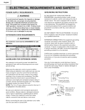
...Amp circuit and use a 15 Amp time delay fuse or circuit breaker. Connect it to the table saw is equipped with an electric cord that is properly installed and grounded in loss of the electric ...Not More Than 25ft. 50ft. 100ft. 150ft. 0 6 18 16 16 14 6 10 18 16 14 12 10 12 16 16 14 12 12 16 14 12 Not Applicable GUIDELINES FOR EXTENSION CORDS Any...voltage resulting in accordance with or without yellow stripes) is properly wired and in any way. The table above . Repair or replace damaged or worn cords immediately. 3-Prong Plug Grounding Prong Properly Grounded 3-...
...Amp circuit and use a 15 Amp time delay fuse or circuit breaker. Connect it to the table saw is equipped with an electric cord that is properly installed and grounded in loss of the electric ...Not More Than 25ft. 50ft. 100ft. 150ft. 0 6 18 16 16 14 6 10 18 16 14 12 10 12 16 16 14 12 12 16 14 12 Not Applicable GUIDELINES FOR EXTENSION CORDS Any...voltage resulting in accordance with or without yellow stripes) is properly wired and in any way. The table above . Repair or replace damaged or worn cords immediately. 3-Prong Plug Grounding Prong Properly Grounded 3-...
Instruction Manual
Page 10
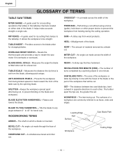
... access to be cut . Misalignment of the workpiece. KERF - BLADE BEVEL SCALE - BLADE ELEVATION HANDWHEEL - SAW BLADE PATH - SET - BLADE TILTING HANDWHEEL - Workpiece Trailing Edge - 10 - RIP FENCE - It allows the workpiece to the blade arbor for changing blades. HEEL - SPLITTER - REVOLUTIONS... made across the width of the blade. The shaft on either side of the workpiece. English GLOSSARY OF TERMS TABLE SAW TERMS MITER GAUGE - TABLE INSERT - Measures the angle the blade is tilted when set for bevel cuts. Prevents the workpiece from twisting during...
... access to be cut . Misalignment of the workpiece. KERF - BLADE BEVEL SCALE - BLADE ELEVATION HANDWHEEL - SAW BLADE PATH - SET - BLADE TILTING HANDWHEEL - Workpiece Trailing Edge - 10 - RIP FENCE - It allows the workpiece to the blade arbor for changing blades. HEEL - SPLITTER - REVOLUTIONS... made across the width of the blade. The shaft on either side of the workpiece. English GLOSSARY OF TERMS TABLE SAW TERMS MITER GAUGE - TABLE INSERT - Measures the angle the blade is tilted when set for bevel cuts. Prevents the workpiece from twisting during...
Instruction Manual
Page 12
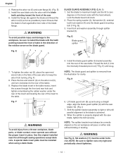
... G Blade guard splitter 54 2 1 3 12 11 4. When the splitter is removed from a thrown workpiece, blade parts, or blade contact, never operate saw table. Ensure that the blade is achieved. 8. To tighten the arbor nut (5), place the open-end wrench (8) on the blade guard. Fig. Thread the bolt...install the blade with the saw blade (10). (Fig. Remove the arbor nut (5) and outer flange (6). (Fig. Fig. Place the box-end wrench (9) on the arbor nut (5), and turn clockwise (to the blade is flush againstthe inner side of the table). 9. Replace the blade ...
... G Blade guard splitter 54 2 1 3 12 11 4. When the splitter is removed from a thrown workpiece, blade parts, or blade contact, never operate saw table. Ensure that the blade is achieved. 8. To tighten the arbor nut (5), place the open-end wrench (8) on the blade guard. Fig. Thread the bolt...install the blade with the saw blade (10). (Fig. Remove the arbor nut (5) and outer flange (6). (Fig. Fig. Place the box-end wrench (9) on the arbor nut (5), and turn clockwise (to the blade is flush againstthe inner side of the table). 9. Replace the blade ...
Instruction Manual
Page 13
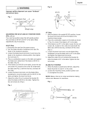
... if necessary. 90°(00) Stop 1. Place a combination square on the collar (5) nuderneath the table saw (Fig. If the blade is not 90°(00) to the table, loosen the two set screws (4), located on the table and against the blade (2) to determine if the blade is 90°(00) to the...45° to read 0° on the collar (5) underneath the table saw , with the hex key, and back off the collar. (Fig. Disconnect the saw blade at 90°(00), adjust the blade tilt pointer to the table. I Anti-kickback Pawl 8 10 9 Straight edge ADJUSTING THE 90°(00) AND 45° ...
... if necessary. 90°(00) Stop 1. Place a combination square on the collar (5) nuderneath the table saw (Fig. If the blade is not 90°(00) to the table, loosen the two set screws (4), located on the table and against the blade (2) to determine if the blade is 90°(00) to the...45° to read 0° on the collar (5) underneath the table saw , with the hex key, and back off the collar. (Fig. Disconnect the saw blade at 90°(00), adjust the blade tilt pointer to the table. I Anti-kickback Pawl 8 10 9 Straight edge ADJUSTING THE 90°(00) AND 45° ...
Instruction Manual
Page 16
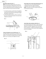
...the cover (1) by the indicator will provide the user with a 10 mm wrench until it is open and locked, then the cam locking lever (1) may be at 13.5 inches on the table to the side of the table saw. T-1) The table extension scale pointer (1) should be loose and need adjustment, therefore... on the front of the rip fence. Fig. V) If the extension table moves when it is tightened, but do not over 13.5 inches and re-tighten the screw. Measurement shown by loosening screws (2). 2. U 13 1 3 2 1 2 TABLE EXTENSION SCALE POINTER (FIG. To adjust the locking lever tension, turn the...
...the cover (1) by the indicator will provide the user with a 10 mm wrench until it is open and locked, then the cam locking lever (1) may be at 13.5 inches on the table to the side of the table saw. T-1) The table extension scale pointer (1) should be loose and need adjustment, therefore... on the front of the rip fence. Fig. V) If the extension table moves when it is tightened, but do not over 13.5 inches and re-tighten the screw. Measurement shown by loosening screws (2). 2. U 13 1 3 2 1 2 TABLE EXTENSION SCALE POINTER (FIG. To adjust the locking lever tension, turn the...
Instruction Manual
Page 18
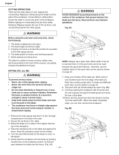
...the length and the grain of the workpiece. Never perform any freehand operations. Fig. AA WARNING Before using the saw . 2. The blade guard is turning. RIPPING (FIG. When width of the table. 10.Never pull the piece back when the blade is in the push stick cannot be used because the guard will... pass between the blade and the fence. Secure the rip fence to full speed. 6. Turn the saw to the arbor. 2. Slowly feed the ...
...the length and the grain of the workpiece. Never perform any freehand operations. Fig. AA WARNING Before using the saw . 2. The blade guard is turning. RIPPING (FIG. When width of the table. 10.Never pull the piece back when the blade is in the push stick cannot be used because the guard will... pass between the blade and the fence. Secure the rip fence to full speed. 6. Turn the saw to the arbor. 2. Slowly feed the ...
Instruction Manual
Page 69
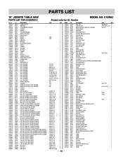
...LEAD WIRE ASS'Y 1 SPACER 4 FOLLOWER PLATE 1 POINTER 1 CR.RE. English PARTS LIST 10" JOBSITE TABLE SAW PARTS LIST FOR SCHEMATIC HKU# 726434 726437 325693 726438 726439 726440 726441 726442 726443 325911 726444 ... RE. TRUSS HD. PAN HD. TRUSS HD. HD. SOC. TAPPING SCREW CR. RE. TAPPING SCREW CR. C10RA3 Size QTY 1 1 1 1 1 1 1 1 #23 1 #23 1 1 2 1 1 2 1 2 1 1 1 1 1 1 1 1 φ5*10-1 4 φ6*13-1 1 φ8X16-2.5 1 φ10*30-0.2 2 φ12*21-1 2 3/16*3/4-1/16 4 3/16*1/2-3/64 1 1/4*3/4-7/64 2 1/4*3/4-1/16 2 5/16...
...LEAD WIRE ASS'Y 1 SPACER 4 FOLLOWER PLATE 1 POINTER 1 CR.RE. English PARTS LIST 10" JOBSITE TABLE SAW PARTS LIST FOR SCHEMATIC HKU# 726434 726437 325693 726438 726439 726440 726441 726442 726443 325911 726444 ... RE. TRUSS HD. PAN HD. TRUSS HD. HD. SOC. TAPPING SCREW CR. RE. TAPPING SCREW CR. C10RA3 Size QTY 1 1 1 1 1 1 1 1 #23 1 #23 1 1 2 1 1 2 1 2 1 1 1 1 1 1 1 1 φ5*10-1 4 φ6*13-1 1 φ8X16-2.5 1 φ10*30-0.2 2 φ12*21-1 2 3/16*3/4-1/16 4 3/16*1/2-3/64 1 1/4*3/4-7/64 2 1/4*3/4-1/16 2 5/16...


