Manual
Page 3
... revision before updating motherboard BIOS, drivers, or when looking for technical information. Disclaimer Information in any form or by copyright laws and is the property of the motherboard is protected by any means without prior notice. For product-related information, check on our website at: http://www.gigabyte.com.tw Identifying Your...
... revision before updating motherboard BIOS, drivers, or when looking for technical information. Disclaimer Information in any form or by copyright laws and is the property of the motherboard is protected by any means without prior notice. For product-related information, check on our website at: http://www.gigabyte.com.tw Identifying Your...
Manual
Page 4
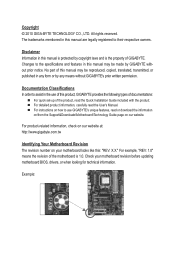
Table of Contents Box Contents...6 Optional Items...6 GA-880GM-UD2H/GA-880GM-US2H Motherboard Layout 7 GA-880GM-UD2H/GA-880GM-US2H Motherboard Block Diagram 8 Chapter 1 Hardware Installation 9 1-1 Installation Precautions 9 1-2 Product Specifications 10 1-3 Installing the CPU... Configuration 19 1-7 Back Panel Connectors 20 1-8 Internal Connectors 23 Chapter 2 BIOS Setup 33 2-1 Startup Screen 34 2-2 The Main Menu 35 2-3 MB Intelligent Tweaker(M.I.T 37 2-4 Standard CMOS Features 44 2-5 Advanced BIOS Features 46 2-6 Integrated Peripherals 48 2-7 Power Management Setup 51 2-8 PnP/PCI...
Table of Contents Box Contents...6 Optional Items...6 GA-880GM-UD2H/GA-880GM-US2H Motherboard Layout 7 GA-880GM-UD2H/GA-880GM-US2H Motherboard Block Diagram 8 Chapter 1 Hardware Installation 9 1-1 Installation Precautions 9 1-2 Product Specifications 10 1-3 Installing the CPU... Configuration 19 1-7 Back Panel Connectors 20 1-8 Internal Connectors 23 Chapter 2 BIOS Setup 33 2-1 Startup Screen 34 2-2 The Main Menu 35 2-3 MB Intelligent Tweaker(M.I.T 37 2-4 Standard CMOS Features 44 2-5 Advanced BIOS Features 46 2-6 Integrated Peripherals 48 2-7 Power Management Setup 51 2-8 PnP/PCI...
Manual
Page 5
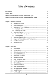
... Contact...61 3-5 System...61 3-6 Download Center 62 3-7 New Utilities...62 Chapter 4 Unique Features 63 4-1 Xpress Recovery2 63 4-2 BIOS Update Utilities 66 4-2-1 Updating the BIOS with the Q-Flash Utility 66 4-2-2 Updating the BIOS with the @BIOS Utility 69 4-3 EasyTune 6...70 4-4 Easy Energy Saver 71 4-5 Q-Share...73 4-6 SMART Recovery 74 4-7 Auto Green...75 Chapter... Microphone Recording 94 5-2-5 Using the Sound Recorder 96 5-3 Troubleshooting 97 5-3-1 Frequently Asked Questions 97 5-3-2 Troubleshooting Procedure 98 5-4 Regulatory Statements 100 j Only for GA-880GM-UD2H - 5 -
... Contact...61 3-5 System...61 3-6 Download Center 62 3-7 New Utilities...62 Chapter 4 Unique Features 63 4-1 Xpress Recovery2 63 4-2 BIOS Update Utilities 66 4-2-1 Updating the BIOS with the Q-Flash Utility 66 4-2-2 Updating the BIOS with the @BIOS Utility 69 4-3 EasyTune 6...70 4-4 Easy Energy Saver 71 4-5 Q-Share...73 4-6 SMART Recovery 74 4-7 Auto Green...75 Chapter... Microphone Recording 94 5-2-5 Using the Sound Recorder 96 5-3 Troubleshooting 97 5-3-1 Frequently Asked Questions 97 5-3-2 Troubleshooting Procedure 98 5-4 Regulatory Statements 100 j Only for GA-880GM-UD2H - 5 -
Manual
Page 8
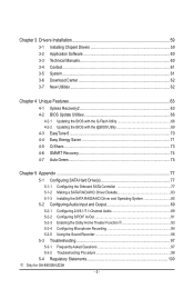
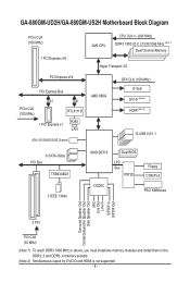
GA-880GM-UD2H/GA-880GM-US2H Motherboard Block Diagram PCIe CLK (100 MHz) 1 PCI Express x16 PCI Express x16 PCI Express Bus x1 x1 PCIe CLK (100 MHz) RTL8111D RJ45 1 ... Hyper Transport 3.0 AMD 880G GFX CLK (100 MHz) D-Sub DVI-D (Note 2) HDMI (Note 2) 12 USB 2.0/1.1 6 SATA 3Gb/s PCI Bus TSB43AB23 2 IEEE 1394a AMD SB710 Dual BIOS LPC Bus IT8720 CODEC Floppy COM Port PS/2 KB/Mouse Surround Speaker Out Center/Subwoofer Speaker Out Side Speaker Out MIC Line Out Line In...
GA-880GM-UD2H/GA-880GM-US2H Motherboard Block Diagram PCIe CLK (100 MHz) 1 PCI Express x16 PCI Express x16 PCI Express Bus x1 x1 PCIe CLK (100 MHz) RTL8111D RJ45 1 ... Hyper Transport 3.0 AMD 880G GFX CLK (100 MHz) D-Sub DVI-D (Note 2) HDMI (Note 2) 12 USB 2.0/1.1 6 SATA 3Gb/s PCI Bus TSB43AB23 2 IEEE 1394a AMD SB710 Dual BIOS LPC Bus IT8720 CODEC Floppy COM Port PS/2 KB/Mouse Surround Speaker Out Center/Subwoofer Speaker Out Side Speaker Out MIC Line Out Line In...
Manual
Page 12
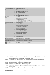
.../System fan fail warning CPU/System fan speed control (Note 5) 2 x 8 Mbit flash Use of licensed AWARD BIOS Support for DualBIOS™ PnP 1.0a, DMI 2.0, SM BIOS 2.4, ACPI 1.0b Support for @BIOS Support for Q-Flash Support for Xpress BIOS Rescue Support for Download Center Support for Xpress Install Support for Xpress Recovery2 Support for EasyTune...
.../System fan fail warning CPU/System fan speed control (Note 5) 2 x 8 Mbit flash Use of licensed AWARD BIOS Support for DualBIOS™ PnP 1.0a, DMI 2.0, SM BIOS 2.4, ACPI 1.0b Support for @BIOS Support for Q-Flash Support for Xpress BIOS Rescue Support for Download Center Support for Xpress Install Support for Xpress Recovery2 Support for EasyTune...
Manual
Page 16
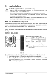
... DDR3_2 DDR3_3 DDR3_4 Due to prevent hardware damage. • Memory modules have a foolproof design. Dual Channel mode cannot be used . (Go to GIGABYTE's website for optimum performance. 1-4 Installing the Memory Read the following guidelines before installing the memory in the DDR3_1 and DDR3_2 sockets. When enabling Dual ... - - - - - After the memory is recommended that the motherboard supports the memory. The four DDR3 memory sockets are to be installed, it is installed, the BIOS will double the original memory bandwidth. Hardware Installation - 16 -
... DDR3_2 DDR3_3 DDR3_4 Due to prevent hardware damage. • Memory modules have a foolproof design. Dual Channel mode cannot be used . (Go to GIGABYTE's website for optimum performance. 1-4 Installing the Memory Read the following guidelines before installing the memory in the DDR3_1 and DDR3_2 sockets. When enabling Dual ... - - - - - After the memory is recommended that the motherboard supports the memory. The four DDR3 memory sockets are to be installed, it is installed, the BIOS will double the original memory bandwidth. Hardware Installation - 16 -
Manual
Page 18
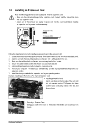
Remove the metal slot cover from the power outlet before you begin to make any required BIOS changes for your expansion card in the slot and does not rock. • Removing a Graphics Card: Gently push back on the lever on the card ... install your expansion card(s). 7. Turn on the top edge of the card until it is securely seated in the expansion slot. 1. If necessary, go to BIOS Setup to install an expansion card: • Make sure the motherboard supports the expansion card. Install the driver provided with a screw. 5. Example: Installing and Removing...
Remove the metal slot cover from the power outlet before you begin to make any required BIOS changes for your expansion card in the slot and does not rock. • Removing a Graphics Card: Gently push back on the lever on the card ... install your expansion card(s). 7. Turn on the top edge of the card until it is securely seated in the expansion slot. 1. If necessary, go to BIOS Setup to install an expansion card: • Make sure the motherboard supports the expansion card. Install the driver provided with a screw. 5. Example: Installing and Removing...
Manual
Page 19
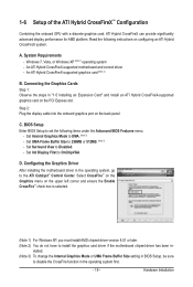
...an Expansion Card" and install an ATI Hybrid CrossFireX-supported graphics card on configuring an ATI Hybrid CrossFireX system. BIOS Setup Enter BIOS Setup to the ATI Catalyst™ Control Center. Set UMA Frame Buffer Size to OnChipVGA. Set Init Display ... (Note 3) - Windows 7, Vista, or Windows XP (Note 1) operating system - C. D. Hardware Installation Read the following items under the Advanced BIOS Features menu: - Set Surround View to UMA. (Note 3) - System Requirements - An ATI Hybrid CrossFireX-supported motherboard and correct driver - stalled. ...
...an Expansion Card" and install an ATI Hybrid CrossFireX-supported graphics card on configuring an ATI Hybrid CrossFireX system. BIOS Setup Enter BIOS Setup to the ATI Catalyst™ Control Center. Set UMA Frame Buffer Size to OnChipVGA. Set Init Display ... (Note 3) - Windows 7, Vista, or Windows XP (Note 1) operating system - C. D. Hardware Installation Read the following items under the Advanced BIOS Features menu: - Set Surround View to UMA. (Note 3) - System Requirements - An ATI Hybrid CrossFireX-supported motherboard and correct driver - stalled. ...
Manual
Page 21
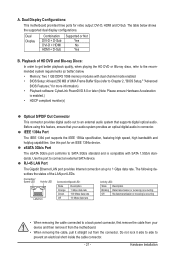
...HDMI + D-Sub Supported or Not Yes No Yes B. The following describes the states of UMA Frame Buffer Size (refer to Chapter 2, "BIOS Setup," "Advanced BIOS Features," for more information) • Playback software: CyberLink PowerDVD 8.0 or later (Note: Please ensure Hardware Acceleration is compatible with dual ...channel mode enabled • BIOS Setup: At least 256 MB of the LAN port LEDs. A. RJ-45 LAN Port The Gigabit Ethernet LAN port provides ...
...HDMI + D-Sub Supported or Not Yes No Yes B. The following describes the states of UMA Frame Buffer Size (refer to Chapter 2, "BIOS Setup," "Advanced BIOS Features," for more information) • Playback software: CyberLink PowerDVD 8.0 or later (Note: Please ensure Hardware Acceleration is compatible with dual ...channel mode enabled • BIOS Setup: At least 256 MB of the LAN port LEDs. A. RJ-45 LAN Port The Gigabit Ethernet LAN port provides ...
Manual
Page 27
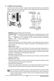
...the hard drive is detected at system startup. The front panel design may differ by issuing a beep code. S1 Blinking tem is detected, the BIOS may configure the way to turn off (S5). • PW (Power Switch, Red): Connects to the pin assignments below. If a problem ...restart. • CI (Chassis Intrusion Header, Gray): Connects to indicate the problem. When connecting your system using the power switch (refer to Chapter 2, "BIOS Setup," "Power Management Setup," for information about beep codes. • HD (Hard Drive Activity LED, Blue) Connects to this header, make sure the ...
...the hard drive is detected at system startup. The front panel design may differ by issuing a beep code. S1 Blinking tem is detected, the BIOS may configure the way to turn off (S5). • PW (Power Switch, Red): Connects to the pin assignments below. If a problem ...restart. • CI (Chassis Intrusion Header, Gray): Connects to indicate the problem. When connecting your system using the power switch (refer to Chapter 2, "BIOS Setup," "Power Management Setup," for information about beep codes. • HD (Hard Drive Activity LED, Blue) Connects to this header, make sure the ...
Manual
Page 31
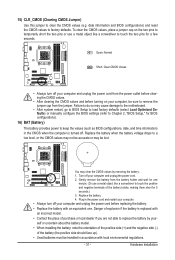
... of the battery holder, making them short for BIOS configurations). 16) BAT (Battery) The battery provides power to factory defaults. date information and BIOS configurations) and reset the CMOS values to keep the values (such as BIOS configurations, date, and time information) in the ... accurate or may cause damage to the motherboard. • After system restart, go to BIOS Setup to load factory defaults (select Load Optimized Defaults) or manually configure the BIOS settings (refer to Chapter 2, "BIOS Setup," for 5 seconds.) 3. Replace the battery. 4. 15) CLR_CMOS (Clearing CMOS Jumper...
... of the battery holder, making them short for BIOS configurations). 16) BAT (Battery) The battery provides power to factory defaults. date information and BIOS configurations) and reset the CMOS values to keep the values (such as BIOS configurations, date, and time information) in the ... accurate or may cause damage to the motherboard. • After system restart, go to BIOS Setup to load factory defaults (select Load Optimized Defaults) or manually configure the BIOS settings (refer to Chapter 2, "BIOS Setup," for 5 seconds.) 3. Replace the battery. 4. 15) CLR_CMOS (Clearing CMOS Jumper...
Manual
Page 33
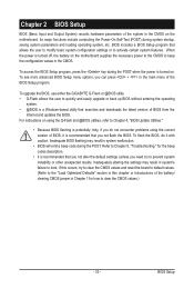
..., saving system parameters and loading operating system, etc. Its major functions include conducting the Power-On Self-Test (POST) during the POST. To upgrade the BIOS, use either the GIGABYTE Q-Flash or @BIOS utility. • Q-Flash allows the user to prevent system instability or other unexpected results. To see more advanced...
..., saving system parameters and loading operating system, etc. Its major functions include conducting the Power-On Self-Test (POST) during the POST. To upgrade the BIOS, use either the GIGABYTE Q-Flash or @BIOS utility. • Q-Flash allows the user to prevent system instability or other unexpected results. To see more advanced...
Manual
Page 34
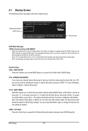
GA-880GM-US2H E4 . . . . : BIOS Setup : XpressRecovery2 : Boot Menu : Qflash 02/10/2010-RS880-SB710-7A66BG0GC-00 Function Keys SATA Mode Message: "SATA is set the first boot device without having to enter BIOS Setup first. When the motherboard is found running at IDE mode. After system restart, the ...to select the first boot device, then press to access the Q-Flash utility in time. You can be based on BIOS Setup settings. Motherboard Model BIOS Version Award Modular BIOS v6.00PG, An Energy Star Ally Copyright (C) 1984-2010, Award Software, Inc. Press to enable AHCI mode or...
GA-880GM-US2H E4 . . . . : BIOS Setup : XpressRecovery2 : Boot Menu : Qflash 02/10/2010-RS880-SB710-7A66BG0GC-00 Function Keys SATA Mode Message: "SATA is set the first boot device without having to enter BIOS Setup first. When the motherboard is found running at IDE mode. After system restart, the ...to select the first boot device, then press to access the Q-Flash utility in time. You can be based on BIOS Setup settings. Motherboard Model BIOS Version Award Modular BIOS v6.00PG, An Energy Star Ally Copyright (C) 1984-2010, Award Software, Inc. Press to enable AHCI mode or...
Manual
Page 35
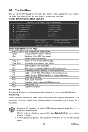
... screen. Use arrow keys to move among the items and press to accept or enter a sub-menu. (Sample BIOS Version: GA-880GM-US2H, E4) CMOS Setup Utility-Copyright (C) 1984-2010 Award Software MB Intelligent Tweaker(M.I.T.) Standard CMOS Features Advanced... BIOS Features Integrated Peripherals Power Management Setup PnP/PCI Configurations PC Health Status Load Fail-...
... screen. Use arrow keys to move among the items and press to accept or enter a sub-menu. (Sample BIOS Version: GA-880GM-US2H, E4) CMOS Setup Utility-Copyright (C) 1984-2010 Award Software MB Intelligent Tweaker(M.I.T.) Standard CMOS Features Advanced... BIOS Features Integrated Peripherals Power Management Setup PnP/PCI Configurations PC Health Status Load Fail-...
Manual
Page 36
...CMOS Features Use this menu to configure the system time and date, hard drive types, floppy disk drive types, and the type of reconfiguring the BIOS settings. Pressing to a profile. You can use the SPACE key) and then press to complete. F12: Load CMOS from a profile ...created before, without the hassles of errors that stop the system boot, etc. Advanced BIOS Features Use this menu to configure the device boot order, advanced features available on the CPU, and the primary display adapter. Integrated Peripherals ...
...CMOS Features Use this menu to configure the system time and date, hard drive types, floppy disk drive types, and the type of reconfiguring the BIOS settings. Pressing to a profile. You can use the SPACE key) and then press to complete. F12: Load CMOS from a profile ...created before, without the hassles of errors that stop the system boot, etc. Advanced BIOS Features Use this menu to configure the device boot order, advanced features available on the CPU, and the primary display adapter. Integrated Peripherals ...
Manual
Page 37
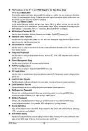
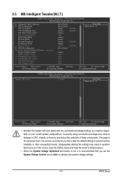
BIOS Setup If this occurs, clear the CMOS values and reset the board to optimize the system voltage settings. - 37 - CPU Host Clock Control x CPU Frequency(...
BIOS Setup If this occurs, clear the CMOS values and reset the board to optimize the system voltage settings. - 37 - CPU Host Clock Control x CPU Frequency(...
Manual
Page 38
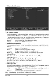
... is configurable only when Advanced Clock Calibration is enabled. CPU core Control Allows you to determine whether to All Cores. Auto Lets the BIOS to be configurable. Normal Uses the standard AMD EC firmware version. (Default) Hybrid Uses the specific AMD EC firmware version. Per Core...Optimized Defaults EC Firmware Selection Allows you to take effect. After the selection, select Save & Exit Setup in the BIOS Main Menu and then press . A message which says "BIOS Is Updating EC Firmware!!! Options are: Auto (default), Manual. Wait for all CPU cores (number of cores available...
... is configurable only when Advanced Clock Calibration is enabled. CPU core Control Allows you to determine whether to All Cores. Auto Lets the BIOS to be configurable. Normal Uses the standard AMD EC firmware version. (Default) Hybrid Uses the specific AMD EC firmware version. Per Core...Optimized Defaults EC Firmware Selection Allows you to take effect. After the selection, select Save & Exit Setup in the BIOS Main Menu and then press . A message which says "BIOS Is Updating EC Firmware!!! Options are: Auto (default), Manual. Wait for all CPU cores (number of cores available...
Manual
Page 39
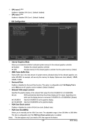
...(Default: Disabled) Onboard VGA output connect Specifies the graphics display of the onboard VGA output from 200 MHz to 2000 MHz. BIOS Setup Surround View Enables or disables the Surround View function. UMA Allocates memory for the onboard graphics controller. This option is configurable ...CPU that supports this memory for the onboard graphics controller. MS-DOS, for example, will use only this feature. - 39 - Auto BIOS automatically determines the primary display port for output, depending on to which port the display device is enabled. (Note) This item appears ...
...(Default: Disabled) Onboard VGA output connect Specifies the graphics display of the onboard VGA output from 200 MHz to 2000 MHz. BIOS Setup Surround View Enables or disables the Surround View function. UMA Allocates memory for the onboard graphics controller. This option is configurable ...CPU that supports this memory for the onboard graphics controller. MS-DOS, for example, will use only this feature. - 39 - Auto BIOS automatically determines the primary display port for output, depending on to which port the display device is enabled. (Note) This item appears ...
Manual
Page 40
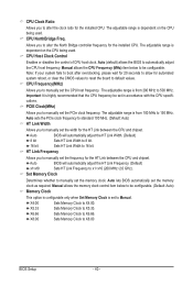
...set to alter the North Bridge controller frequency for automated system reboot, or clear the CMOS values to reset the board to X6.66. Auto BIOS will automatically adjust the HT Link Frequency. (Default) x1~x10 Sets HT Link Frequency to X4.00. The adjustable range is from 100 ... Frequency(MHz) Allows you to manually set in accordance with the CPU specifications. PCIE Clock(MHz) Allows you to manually set the memory clock. Auto BIOS will automatically adjust the HT Link Width. (Default) 8 bit Sets HT Link Width to 8 bit. 16 bit Sets HT Link Width to be ...
...set to alter the North Bridge controller frequency for automated system reboot, or clear the CMOS values to reset the board to X6.66. Auto BIOS will automatically adjust the HT Link Frequency. (Default) x1~x10 Sets HT Link Frequency to X4.00. The adjustable range is from 100 ... Frequency(MHz) Allows you to manually set in accordance with the CPU specifications. PCIE Clock(MHz) Allows you to manually set the memory clock. Auto BIOS will automatically adjust the HT Link Width. (Default) 8 bit Sets HT Link Width to 8 bit. 16 bit Sets HT Link Width to be ...
Manual
Page 41
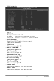
CAS# latency Options are : Auto (default), 5T~12T. BIOS Setup RAS to set memory control mode. Row Precharge Time Options are : Auto (default), 1T, 2T. Minimum RAS Active Time Options are: Auto (default), 15T~...
CAS# latency Options are : Auto (default), 5T~12T. BIOS Setup RAS to set memory control mode. Row Precharge Time Options are : Auto (default), 1T, 2T. Minimum RAS Active Time Options are: Auto (default), 15T~...


