Manual
Page 4
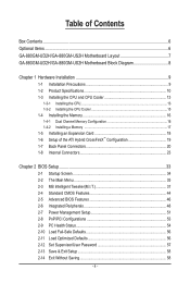
Table of Contents Box Contents...6 Optional Items...6 GA-880GM-UD2H/GA-880GM-US2H Motherboard Layout 7 GA-880GM-UD2H/GA-880GM-US2H Motherboard Block Diagram 8 Chapter 1 Hardware Installation 9 1-1 Installation Precautions 9 1-2 Product Specifications 10 1-3 Installing the CPU and CPU Cooler 13 1-3-1 Installing the CPU 13 1-3-2 Installing the CPU Cooler 15 1-4 Installing the Memory 16 1-4-1 Dual Channel Memory Configuration 16 1-4-2 Installing a Memory 17 1-5 Installing an Expansion Card 18...
Table of Contents Box Contents...6 Optional Items...6 GA-880GM-UD2H/GA-880GM-US2H Motherboard Layout 7 GA-880GM-UD2H/GA-880GM-US2H Motherboard Block Diagram 8 Chapter 1 Hardware Installation 9 1-1 Installation Precautions 9 1-2 Product Specifications 10 1-3 Installing the CPU and CPU Cooler 13 1-3-1 Installing the CPU 13 1-3-2 Installing the CPU Cooler 15 1-4 Installing the Memory 16 1-4-1 Dual Channel Memory Configuration 16 1-4-2 Installing a Memory 17 1-5 Installing an Expansion Card 18...
Manual
Page 8
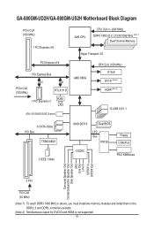
GA-880GM-UD2H/GA-880GM-US2H Motherboard Block Diagram PCIe CLK (100 MHz) 1 PCI Express x16 PCI Express x16 PCI Express Bus x1 x1 PCIe CLK (100 MHz) RTL8111D RJ45 1 PCI Express x1 LAN ATA-133/100/66/33 IDE Channel AM3 CPU CPU CLK+/- (200 MHz) DDR3 1800 (O.C.)/1333/1066 MHz (Note 1) Dual Channel Memory Hyper Transport...
GA-880GM-UD2H/GA-880GM-US2H Motherboard Block Diagram PCIe CLK (100 MHz) 1 PCI Express x16 PCI Express x16 PCI Express Bus x1 x1 PCIe CLK (100 MHz) RTL8111D RJ45 1 PCI Express x1 LAN ATA-133/100/66/33 IDE Channel AM3 CPU CPU CLK+/- (200 MHz) DDR3 1800 (O.C.)/1333/1066 MHz (Note 1) Dual Channel Memory Hyper Transport...
Manual
Page 9
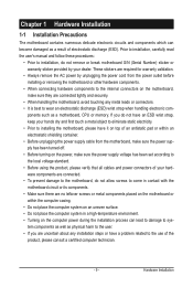
... are connected. • To prevent damage to the motherboard, do not have an ESD wrist strap, keep your dealer. Hardware Installation ponents such as a motherboard, CPU or memory. Chapter 1 Hardware Installation 1-1 Installation Precautions The motherboard contains numerous delicate electronic circuits and components which can lead to damage to system components as...
... are connected. • To prevent damage to the motherboard, do not have an ESD wrist strap, keep your dealer. Hardware Installation ponents such as a motherboard, CPU or memory. Chapter 1 Hardware Installation 1-1 Installation Precautions The motherboard contains numerous delicate electronic circuits and components which can lead to damage to system components as...
Manual
Page 10
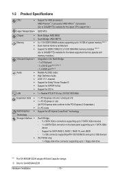
... up to 1 floppy disk drive "*" The GA-880GM-UD2H adopts All-Solid Capacitor design. 1-2 Product Specifications CPU Support for AM3 processors: AMD Phenom™ II processor/ AMD Athlon™ II processor (Go to GIGABYTE's website for the latest CPU support list.) Hyper Transport Bus 5200 ... to 16 GB of system memory (Note 1) Dual channel memory architecture Support for DDR3 1800(O.C.)/1333/1066 MHz memory modules (Note 2) (Go to GIGABYTE's website for the latest supported memory speeds and memory modules.) Integrated in the North Bridge: - 1 x D-Sub port - 1 x DVI-D port...
... up to 1 floppy disk drive "*" The GA-880GM-UD2H adopts All-Solid Capacitor design. 1-2 Product Specifications CPU Support for AM3 processors: AMD Phenom™ II processor/ AMD Athlon™ II processor (Go to GIGABYTE's website for the latest CPU support list.) Hyper Transport Bus 5200 ... to 16 GB of system memory (Note 1) Dual channel memory architecture Support for DDR3 1800(O.C.)/1333/1066 MHz memory modules (Note 2) (Go to GIGABYTE's website for the latest supported memory speeds and memory modules.) Integrated in the North Bridge: - 1 x D-Sub port - 1 x DVI-D port...
Manual
Page 11
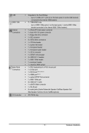
... IEEE 1394a headers) Internal w 1 x 24-pin ATX main power connector Connectors w 1 x 8-pin ATX 12V power connector w 1 x floppy disk drive connector w 1 x IDE connector w 5 x SATA 3Gb/s connectors w 1 x CPU fan header w 1 x system fan header w 1 x front panel header w 1 x front panel audio header w 1 x CD In connector w 1 x S/PDIF In/Out header w 3 x USB 2.0/1.1 headers w 1 x IEEE 1394a header w 1 x serial...
... IEEE 1394a headers) Internal w 1 x 24-pin ATX main power connector Connectors w 1 x 8-pin ATX 12V power connector w 1 x floppy disk drive connector w 1 x IDE connector w 5 x SATA 3Gb/s connectors w 1 x CPU fan header w 1 x system fan header w 1 x front panel header w 1 x front panel audio header w 1 x CD In connector w 1 x S/PDIF In/Out header w 3 x USB 2.0/1.1 headers w 1 x IEEE 1394a header w 1 x serial...
Manual
Page 12
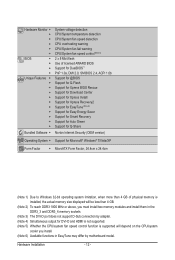
... w w Unique Features w w w w w w w w w w w Bundled Software w System voltage detection CPU/System temperature detection CPU/System fan speed detection CPU overheating warning CPU/System fan fail warning CPU/System fan speed control (Note 5) 2 x 8 Mbit flash Use of licensed AWARD BIOS Support for DualBIOS™ ... for DVI-D and HDMI is not supported. (Note 5) Whether the CPU/system fan speed control function is supported will depend on the CPU/system cooler you install. (Note 6) Available functions in EasyTune may differ...
... w w Unique Features w w w w w w w w w w w Bundled Software w System voltage detection CPU/System temperature detection CPU/System fan speed detection CPU overheating warning CPU/System fan fail warning CPU/System fan speed control (Note 5) 2 x 8 Mbit flash Use of licensed AWARD BIOS Support for DualBIOS™ ... for DVI-D and HDMI is not supported. (Note 5) Whether the CPU/system fan speed control function is supported will depend on the CPU/system cooler you install. (Note 6) Available functions in EasyTune may differ...
Manual
Page 13
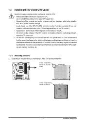
...both sides of the CPU and alignment keys on the CPU socket.) • Apply an even and thin layer of thermal grease on the surface of the CPU. • Do not turn on the computer if the CPU cooler is not recommended that the motherboard supports the CPU. (Go to GIGABYTE's website for the ...peripherals. A Small Triangle Mark Denotes Pin One of the CPU. If you wish to set beyond the standard...
...both sides of the CPU and alignment keys on the CPU socket.) • Apply an even and thin layer of thermal grease on the surface of the CPU. • Do not turn on the computer if the CPU cooler is not recommended that the motherboard supports the CPU. (Go to GIGABYTE's website for the ...peripherals. A Small Triangle Mark Denotes Pin One of the CPU. If you wish to set beyond the standard...
Manual
Page 14
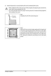
... power cord from the power outlet to prevent damage to the CPU. • Do not force the CPU into their holes. The CPU cannot fit in if oriented incorrectly. Adjust the CPU orientation if this occurs. Make sure that the CPU pins fit perfectly into the CPU socket. CPU Socket Locking Lever Step 1: Completely lift up the...
... power cord from the power outlet to prevent damage to the CPU. • Do not force the CPU into their holes. The CPU cannot fit in if oriented incorrectly. Adjust the CPU orientation if this occurs. Make sure that the CPU pins fit perfectly into the CPU socket. CPU Socket Locking Lever Step 1: Completely lift up the...
Manual
Page 15
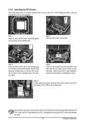
... lug on one side of the retention frame. Step 2: Place the CPU cooler on the CPU. 1-3-2 Installing the CPU Cooler Follow the steps below to correctly install the CPU cooler on the CPU. (The following procedure uses the GIGABYTE cooler as the picture above shows) to lock into place. (Refer ...to your CPU cooler installation manual for instructions on installing the cooler.) Step 5: Finally, attach the power connector of the CPU cooler to the ...
... lug on one side of the retention frame. Step 2: Place the CPU cooler on the CPU. 1-3-2 Installing the CPU Cooler Follow the steps below to correctly install the CPU cooler on the CPU. (The following procedure uses the GIGABYTE cooler as the picture above shows) to lock into place. (Refer ...to your CPU cooler installation manual for instructions on installing the cooler.) Step 5: Finally, attach the power connector of the CPU cooler to the ...
Manual
Page 16
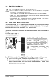
...Dual Channel mode cannot be installed in the DDR3_1 and DDR3_2 sockets. 1-4 Installing the Memory Read the following guidelines before you begin to CPU limitations, read the following : Channel 0: DDR3_1, DDR3_3 Channel 1: DDR3_2, DDR3_4 Dual Channel Memory Configurations Table DDR3_1 DDR3_2 DDR3_3 DDR3_4 Two... two channels and each channel has two memory sockets as following guidelines before installing the memory to be used . (Go to GIGABYTE's website for the latest supported memory speeds and memory modules.) • Always turn off the computer and unplug the power cord...
...Dual Channel mode cannot be installed in the DDR3_1 and DDR3_2 sockets. 1-4 Installing the Memory Read the following guidelines before you begin to CPU limitations, read the following : Channel 0: DDR3_1, DDR3_3 Channel 1: DDR3_2, DDR3_4 Dual Channel Memory Configurations Table DDR3_1 DDR3_2 DDR3_3 DDR3_4 Two... two channels and each channel has two memory sockets as following guidelines before installing the memory to be used . (Go to GIGABYTE's website for the latest supported memory speeds and memory modules.) • Always turn off the computer and unplug the power cord...
Manual
Page 24
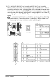
... stable power to an unstable or unbootable system. 1 5 4 8 ATX_12V_2X4 ATX_12V_2X4: Pin No. The power connector possesses a foolproof design. Connect the power supply cable to the CPU. 1/2) ATX_12V_2X4/ATX (2x4 12V Power Connector and 2x12 Main Power Connector) With the use of the power connector, the power supply can lead to all...
... stable power to an unstable or unbootable system. 1 5 4 8 ATX_12V_2X4 ATX_12V_2X4: Pin No. The power connector possesses a foolproof design. Connect the power supply cable to the CPU. 1/2) ATX_12V_2X4/ATX (2x4 12V Power Connector and 2x12 Main Power Connector) With the use of the power connector, the power supply can lead to all...
Manual
Page 25
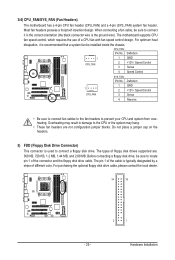
...connector is typically designated by a stripe of different color. The pin 1 of floppy disk drives supported are not configuration jumper blocks. The motherboard supports CPU fan speed control, which requires the use of the connector and the floppy disk drive cable. Definition 1 1 GND CPU_FAN 2 +12V / Speed ... the cable is used to connect a floppy disk drive. For optimum heat dissipation, it in damage to locate pin 1 of a CPU fan with fan speed control design. Overheating may result in the correct orientation (the black connector wire is recommended that a system fan be...
...connector is typically designated by a stripe of different color. The pin 1 of floppy disk drives supported are not configuration jumper blocks. The motherboard supports CPU fan speed control, which requires the use of the connector and the floppy disk drive cable. Definition 1 1 GND CPU_FAN 2 +12V / Speed ... the cable is used to connect a floppy disk drive. For optimum heat dissipation, it in damage to locate pin 1 of a CPU fan with fan speed control design. Overheating may result in the correct orientation (the black connector wire is recommended that a system fan be...
Manual
Page 35
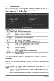
...are for the menu. BIOS Setup Use arrow keys to move among the items and press to accept or enter a sub-menu. (Sample BIOS Version: GA-880GM-US2H, E4) CMOS Setup Utility-Copyright (C) 1984-2010 Award Software MB Intelligent Tweaker(M.I.T.) Standard CMOS Features Advanced BIOS Features ... Saving ESC: Quit F8: Q-Flash Select Item F10: Save & Exit Setup F11: Save CMOS to BIOS F12: Load CMOS from BIOS Change CPU's Clock & Voltage BIOS Setup Program Function Keys Move the selection bar to select an item Execute command or enter the submenu Main Menu: Exit...
...are for the menu. BIOS Setup Use arrow keys to move among the items and press to accept or enter a sub-menu. (Sample BIOS Version: GA-880GM-US2H, E4) CMOS Setup Utility-Copyright (C) 1984-2010 Award Software MB Intelligent Tweaker(M.I.T.) Standard CMOS Features Advanced BIOS Features ... Saving ESC: Quit F8: Q-Flash Select Item F10: Save & Exit Setup F11: Save CMOS to BIOS F12: Load CMOS from BIOS Change CPU's Clock & Voltage BIOS Setup Program Function Keys Move the selection bar to select an item Execute command or enter the submenu Main Menu: Exit...
Manual
Page 36
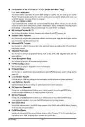
...that stop the system boot, etc. Advanced BIOS Features Use this menu to configure the device boot order, advanced features available on the CPU, and the primary display adapter. Integrated Peripherals Use this menu to configure all peripheral devices, such as IDE, SATA, USB, integrated...Use this menu to configure the system's PCI & PnP resources. PC Health Status Use this menu to see information about autodetected system/CPU temperature, system voltage and fan speed, etc. Load Fail-Safe Defaults Fail-Safe defaults are factory settings for the most stable, ...
...that stop the system boot, etc. Advanced BIOS Features Use this menu to configure the device boot order, advanced features available on the CPU, and the primary display adapter. Integrated Peripherals Use this menu to configure all peripheral devices, such as IDE, SATA, USB, integrated...Use this menu to configure the system's PCI & PnP resources. PC Health Status Use this menu to see information about autodetected system/CPU temperature, system voltage and fan speed, etc. Load Fail-Safe Defaults Fail-Safe defaults are factory settings for the most stable, ...
Manual
Page 37
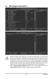
...Memory Clock } DRAM Configuration ******** System Voltage Optimized ******** System Voltage Control x DDR3 Voltage Control x NorthBridge Volt Control x SouthBridge Volt Control x CPU NB VID Control x CPU Voltage Control [Press Enter] [Press Enter] [Auto] 2800Mhz [Auto] 2000Mhz [Auto] 200 [Auto] [Auto] [Auto] 2000Mhz [Auto...recommended that you made is for advanced users only and we recommend you not to alter the default settings to CPU, chipset, or memory and reduce the useful life of these components. 2-3 MB Intelligent Tweaker(M.I.T.) CMOS Setup Utility...
...Memory Clock } DRAM Configuration ******** System Voltage Optimized ******** System Voltage Control x DDR3 Voltage Control x NorthBridge Volt Control x SouthBridge Volt Control x CPU NB VID Control x CPU Voltage Control [Press Enter] [Press Enter] [Auto] 2800Mhz [Auto] 2000Mhz [Auto] 200 [Auto] [Auto] [Auto] 2000Mhz [Auto...recommended that you made is for advanced users only and we recommend you not to alter the default settings to CPU, chipset, or memory and reduce the useful life of these components. 2-3 MB Intelligent Tweaker(M.I.T.) CMOS Setup Utility...
Manual
Page 38
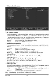
... few seconds and the system will appear. Per Core Individually configures Advanced Clock Calibration for all CPU cores (number of cores available depends on the CPU being used). Value (Core 0), Value (Core 1), Value (Core 2), Value (Core 3) ... Selection Advanced Clock Calibration x Value (All Cores) x Value (Core 0) x Value (Core 1) x Value (Core 2) x Value (Core 3) CPU core Control x CPU core 2 (Note) x CPU core 3 (Note) [Normal] [Disabled] -2% -2% -2% -2% -2% [Auto] Enabled Enabled Item Help Menu Level Move Enter: Select...
... few seconds and the system will appear. Per Core Individually configures Advanced Clock Calibration for all CPU cores (number of cores available depends on the CPU being used). Value (Core 0), Value (Core 1), Value (Core 2), Value (Core 3) ... Selection Advanced Clock Calibration x Value (All Cores) x Value (Core 0) x Value (Core 1) x Value (Core 2) x Value (Core 3) CPU core Control x CPU core 2 (Note) x CPU core 3 (Note) [Normal] [Disabled] -2% -2% -2% -2% -2% [Auto] Enabled Enabled Item Help Menu Level Move Enter: Select...
Manual
Page 39
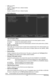
... is configurable only if the VGA Core Clock control option is enabled. (Note) This item appears only if you install a CPU that supports this memory for display. Auto BIOS automatically determines the primary display port for example, will use only this feature. ... Clock(MHz) Allows you to determine whether to allocate system memory for the onboard graphics controller. CPU core 2 (Note) Enables or disables CPU Core 2. (Default: Enabled) CPU core 3 (Note) Enables or disables CPU Core 3. (Default: Enabled) IGX Configuration CMOS Setup Utility-Copyright (C) 1984-2010 Award Software IGX...
... is configurable only if the VGA Core Clock control option is enabled. (Note) This item appears only if you install a CPU that supports this memory for display. Auto BIOS automatically determines the primary display port for example, will use only this feature. ... Clock(MHz) Allows you to determine whether to allocate system memory for the onboard graphics controller. CPU core 2 (Note) Enables or disables CPU Core 2. (Default: Enabled) CPU core 3 (Note) Enables or disables CPU Core 3. (Default: Enabled) IGX Configuration CMOS Setup Utility-Copyright (C) 1984-2010 Award Software IGX...
Manual
Page 40
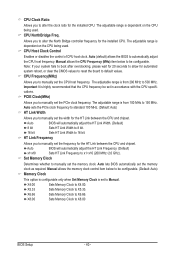
....66 Sets Memory Clock to X8.00 BIOS Setup - 40 - X8.00 Sets Memory Clock to X6.66. The adjustable range is dependent on the CPU being used . Auto BIOS will automatically adjust the HT Link Frequency. (Default) x1~x10 Sets HT Link Frequency to x1~x10 (200 MHz~2.0 GHz). X5... allow for automated system reboot, or clear the CMOS values to reset the board to X5.33. Important It is set in accordance with the CPU specifications. Set Memory Clock Determines whether to manually set the memory clock as required. Manual allows the memory clock control item below to be set...
....66 Sets Memory Clock to X8.00 BIOS Setup - 40 - X8.00 Sets Memory Clock to X6.66. The adjustable range is dependent on the CPU being used . Auto BIOS will automatically adjust the HT Link Frequency. (Default) x1~x10 Sets HT Link Frequency to x1~x10 (200 MHz~2.0 GHz). X5... allow for automated system reboot, or clear the CMOS values to reset the board to X5.33. Important It is set in accordance with the CPU specifications. Set Memory Clock Determines whether to manually set the memory clock as required. Manual allows the memory clock control item below to be set...

Manual
Page 43
... range is dependent on the CPU being installed. (Default: Normal) Note: Increasing CPU voltage may result in damage to your CPU or reduce the useful life of the CPU. The adjustable range is dependent on the CPU being installed. (Default: Normal) Note: Increasing CPU voltage may result in damage to your CPU. - 43 - CPU NB VID Control Allows...
... range is dependent on the CPU being installed. (Default: Normal) Note: Increasing CPU voltage may result in damage to your CPU or reduce the useful life of the CPU. The adjustable range is dependent on the CPU being installed. (Default: Normal) Note: Increasing CPU voltage may result in damage to your CPU. - 43 - CPU NB VID Control Allows...
Manual
Page 46
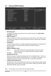
... the boot order from the installed hard drives. AMD C1E Support (Note) Enables or disables the C1E CPU power-saving function in this function. When enabled, the CPU core frequency and voltage will be reduced during system halt state to decrease power consumption. (Default: Disabled)..., CDROM, ZIP, USB-FDD, USB-ZIP, USB-CDROM, USB-HDD, Legacy LAN, Disabled. (Note) This item appears only if you install a CPU that supports this menu when finished. 2-5 Advanced BIOS Features CMOS Setup Utility-Copyright (C) 1984-2010 Award Software Advanced BIOS Features } IGX Configuration AMD C1E ...
... the boot order from the installed hard drives. AMD C1E Support (Note) Enables or disables the C1E CPU power-saving function in this function. When enabled, the CPU core frequency and voltage will be reduced during system halt state to decrease power consumption. (Default: Disabled)..., CDROM, ZIP, USB-FDD, USB-ZIP, USB-CDROM, USB-HDD, Legacy LAN, Disabled. (Note) This item appears only if you install a CPU that supports this menu when finished. 2-5 Advanced BIOS Features CMOS Setup Utility-Copyright (C) 1984-2010 Award Software Advanced BIOS Features } IGX Configuration AMD C1E ...


