Manual
Page 4
... Contents Box Contents...6 Optional Items...6 GA-880GM-UD2H/GA-880GM-US2H Motherboard Layout 7 GA-880GM-UD2H/GA-880GM-US2H Motherboard Block Diagram 8 Chapter 1 Hardware Installation 9 1-1 Installation Precautions 9 1-2 Product Specifications 10 1-3 Installing the CPU and CPU Cooler 13 1-3-1 Installing the CPU 13 1-3-2 Installing the CPU Cooler 15 1-4 Installing the Memory 16 1-4-1 Dual Channel Memory Configuration 16 1-4-2 Installing a Memory 17 1-5 Installing an Expansion Card 18...
... Contents Box Contents...6 Optional Items...6 GA-880GM-UD2H/GA-880GM-US2H Motherboard Layout 7 GA-880GM-UD2H/GA-880GM-US2H Motherboard Block Diagram 8 Chapter 1 Hardware Installation 9 1-1 Installation Precautions 9 1-2 Product Specifications 10 1-3 Installing the CPU and CPU Cooler 13 1-3-1 Installing the CPU 13 1-3-2 Installing the CPU Cooler 15 1-4 Installing the Memory 16 1-4-1 Dual Channel Memory Configuration 16 1-4-2 Installing a Memory 17 1-5 Installing an Expansion Card 18...
Manual
Page 8
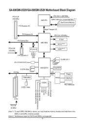
GA-880GM-UD2H/GA-880GM-US2H Motherboard Block Diagram PCIe CLK (100 MHz) 1 PCI Express x16 PCI Express x16 PCI Express Bus x1 x1 PCIe CLK (100 MHz) RTL8111D RJ45 1 PCI Express x1 LAN ATA-133/100/66/33 IDE Channel AM3 CPU CPU CLK+/- (200 MHz) DDR3 1800 (O.C.)/1333/1066 MHz (Note 1) Dual Channel Memory Hyper... Line Out Line In S/PDIF In S/PDIF Out 2 PCI PCI CLK (33 MHz) (Note 1) To reach DDR3 1800 MHz or above, you must install two memory modules and install them in the DDR3_3 and DDR3_4 memory sockets. (Note 2) Simultaneous output for DVD-D and HDMI is not supported. - 8 -
GA-880GM-UD2H/GA-880GM-US2H Motherboard Block Diagram PCIe CLK (100 MHz) 1 PCI Express x16 PCI Express x16 PCI Express Bus x1 x1 PCIe CLK (100 MHz) RTL8111D RJ45 1 PCI Express x1 LAN ATA-133/100/66/33 IDE Channel AM3 CPU CPU CLK+/- (200 MHz) DDR3 1800 (O.C.)/1333/1066 MHz (Note 1) Dual Channel Memory Hyper... Line Out Line In S/PDIF In S/PDIF Out 2 PCI PCI CLK (33 MHz) (Note 1) To reach DDR3 1800 MHz or above, you must install two memory modules and install them in the DDR3_3 and DDR3_4 memory sockets. (Note 2) Simultaneous output for DVD-D and HDMI is not supported. - 8 -
Manual
Page 9
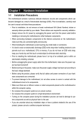
... 1-1 Installation Precautions The motherboard contains numerous delicate electronic circuits and components which can lead to damage to system components as well as a motherboard, CPU or memory. If you are connected tightly and securely. • When handling the motherboard, avoid touching any installation steps or have a problem related to the use of...
... 1-1 Installation Precautions The motherboard contains numerous delicate electronic circuits and components which can lead to damage to system components as well as a motherboard, CPU or memory. If you are connected tightly and securely. • When handling the motherboard, avoid touching any installation steps or have a problem related to the use of...
Manual
Page 10
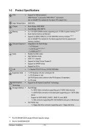
... drive "*" The GA-880GM-UD2H adopts All-Solid Capacitor design. Support for GA-880GM-UD2H Hardware Installation - 10 - 1-2 Product Specifications CPU Support for AM3 processors: AMD Phenom™ II processor/ AMD Athlon™ II processor (Go to GIGABYTE's website for the latest CPU support list.) Hyper Transport Bus 5200 MT/s Chipset Memory Onboard Graphics ...
... drive "*" The GA-880GM-UD2H adopts All-Solid Capacitor design. Support for GA-880GM-UD2H Hardware Installation - 10 - 1-2 Product Specifications CPU Support for AM3 processors: AMD Phenom™ II processor/ AMD Athlon™ II processor (Go to GIGABYTE's website for the latest CPU support list.) Hyper Transport Bus 5200 MT/s Chipset Memory Onboard Graphics ...
Manual
Page 12
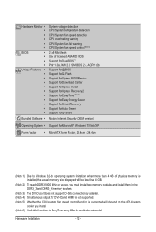
... Form Factor w MicroATX Form Factor; 24.4cm x 24.4cm (Note 1) Due to Windows 32-bit operating system limitation, when more than 4 GB of physical memory is installed, the actual memory size displayed will be less than 4 GB. (Note 2) To reach DDR3 1800 MHz or above, you must install two... memory modules and install them in the DDR3_3 and DDR3_4 memory sockets. (Note 3) The DVI-D port does not support D-Sub connection by adapter. (Note 4) Simultaneous output for DVI-D and HDMI is not supported. ...
... Form Factor w MicroATX Form Factor; 24.4cm x 24.4cm (Note 1) Due to Windows 32-bit operating system limitation, when more than 4 GB of physical memory is installed, the actual memory size displayed will be less than 4 GB. (Note 2) To reach DDR3 1800 MHz or above, you must install two... memory modules and install them in the DDR3_3 and DDR3_4 memory sockets. (Note 3) The DVI-D port does not support D-Sub connection by adapter. (Note 4) Simultaneous output for DVI-D and HDMI is not supported. ...
Manual
Page 13
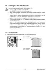
If you wish to set beyond the standard specifications, please do so according to your hardware specifications including the CPU, graphics card, memory, hard drive, etc. 1-3-1 Installing the CPU A. A Small Triangle Mark Denotes Pin One of the CPU socket and the CPU. It is not ...the pin one of thermal grease on the computer if the CPU cooler is not recommended that the motherboard supports the CPU. (Go to GIGABYTE's website for the peripherals. The CPU cannot be set the frequency beyond hardware specifications since it does not meet the standard requirements for the...
If you wish to set beyond the standard specifications, please do so according to your hardware specifications including the CPU, graphics card, memory, hard drive, etc. 1-3-1 Installing the CPU A. A Small Triangle Mark Denotes Pin One of the CPU socket and the CPU. It is not ...the pin one of thermal grease on the computer if the CPU cooler is not recommended that the motherboard supports the CPU. (Go to GIGABYTE's website for the peripherals. The CPU cannot be set the frequency beyond hardware specifications since it does not meet the standard requirements for the...
Manual
Page 16
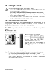
... installed in Dual Channel mode. 1. After the memory is installed. 2. Dual Channel mode cannot be used . (Go to GIGABYTE's website for the latest supported memory speeds and memory modules.) • Always turn off the computer and unplug the power cord from the power outlet before installing the memory in the same colored DDR3 sockets for...
... installed in Dual Channel mode. 1. After the memory is installed. 2. Dual Channel mode cannot be used . (Go to GIGABYTE's website for the latest supported memory speeds and memory modules.) • Always turn off the computer and unplug the power cord from the power outlet before installing the memory in the same colored DDR3 sockets for...
Manual
Page 17
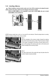
...securely inserted. - 17 - Step 2: The clips at both ends of the socket will snap into the memory socket. Spread the retaining clips at both ends of the memory socket. Place the memory module on this motherboard. DDR3 and DDR2 DIMMs are not compatible to each other or DDR DIMMs. Be sure... to install DDR3 DIMMs on the socket. 1-4-2 Installing a Memory Before installing a memory module, make sure to turn off the computer and unplug the power cord from the power outlet to prevent damage to correctly install your...
...securely inserted. - 17 - Step 2: The clips at both ends of the socket will snap into the memory socket. Spread the retaining clips at both ends of the memory socket. Place the memory module on this motherboard. DDR3 and DDR2 DIMMs are not compatible to each other or DDR DIMMs. Be sure... to install DDR3 DIMMs on the socket. 1-4-2 Installing a Memory Before installing a memory module, make sure to turn off the computer and unplug the power cord from the power outlet to prevent damage to correctly install your...
Manual
Page 21
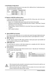
... to a back panel connector, first remove the cable from your audio system provides an optical digital audio in connector. The table below . • Memory: Two 1 GB DDR3 1066 memory modules with SATA 1.5Gb/s standards. The following describes the states of HD DVD and Blu-ray Discs: In order to get better playback...
... to a back panel connector, first remove the cable from your audio system provides an optical digital audio in connector. The table below . • Memory: Two 1 GB DDR3 1066 memory modules with SATA 1.5Gb/s standards. The following describes the states of HD DVD and Blu-ray Discs: In order to get better playback...
Manual
Page 36
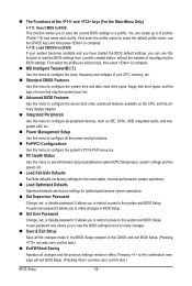
... Change, set , or disable password. You can use the SPACE key) and then press to complete. F12: Load CMOS from BIOS If your CPU, memory, etc. Standard CMOS Features Use this menu to configure the system time and date, hard drive types, floppy disk drive types, and the type...
... Change, set , or disable password. You can use the SPACE key) and then press to complete. F12: Load CMOS from BIOS If your CPU, memory, etc. Standard CMOS Features Use this menu to configure the system time and date, hard drive types, floppy disk drive types, and the type...
Manual
Page 37
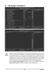
...the board to default values.) • When the System Voltage Optimized item blinks in damage to CPU, chipset, or memory and reduce the useful life of these components. Incorrectly doing overclock/overvoltage may result in system's failure to optimize the... settings. - 37 - CPU Host Clock Control x CPU Frequency(MHz) PCIE Clock(MHz) HT Link Width HT Link Frequency Set Memory Clock x Memory Clock } DRAM Configuration ******** System Voltage Optimized ******** System Voltage Control x DDR3 Voltage Control x NorthBridge Volt Control x SouthBridge Volt Control...
...the board to default values.) • When the System Voltage Optimized item blinks in damage to CPU, chipset, or memory and reduce the useful life of these components. Incorrectly doing overclock/overvoltage may result in system's failure to optimize the... settings. - 37 - CPU Host Clock Control x CPU Frequency(MHz) PCIE Clock(MHz) HT Link Width HT Link Frequency Set Memory Clock x Memory Clock } DRAM Configuration ******** System Voltage Optimized ******** System Voltage Control x DDR3 Voltage Control x NorthBridge Volt Control x SouthBridge Volt Control...
Manual
Page 39
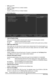
...F6: Fail-Safe Defaults ESC: Exit F1: General Help F7: Optimized Defaults Internal Graphics Mode Allows you to determine whether to allocate system memory for the onboard graphics controller. Options are: Auto (default), 128MB, 256MB, 512MB. This option is configurable only if Init Display First... the control of VGA Core clock. (Default: Auto) VGA Core Clock(MHz) Allows you install a CPU that supports this memory for output, depending on to which port the display device is installed. (Default: Disabled) Onboard VGA output connect Specifies the graphics display ...
...F6: Fail-Safe Defaults ESC: Exit F1: General Help F7: Optimized Defaults Internal Graphics Mode Allows you to determine whether to allocate system memory for the onboard graphics controller. Options are: Auto (default), 128MB, 256MB, 512MB. This option is configurable only if Init Display First... the control of VGA Core clock. (Default: Auto) VGA Core Clock(MHz) Allows you install a CPU that supports this memory for output, depending on to which port the display device is installed. (Default: Disabled) Onboard VGA output connect Specifies the graphics display ...
Manual
Page 40
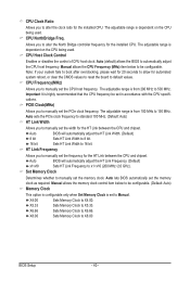
... and chipset. Auto sets the PCIe clock frequency to standard 100 MHz. (Default: Auto) HT Link Width Allows you to X5.33. Manual allows the memory clock control item below to manually set the frequency for the HT Link between the CPU and chipset. CPU NorthBridge Freq. CPU Host Clock Control... reboot, or clear the CMOS values to reset the board to 500 MHz. Manual allows the CPU Frequency (MHz) item below to be set the memory clock as required. The adjustable range is from 100 MHz to x1~x10 (200 MHz~2.0 GHz). Note: If your system fails to boot after overclocking...
... and chipset. Auto sets the PCIe clock frequency to standard 100 MHz. (Default: Auto) HT Link Width Allows you to X5.33. Manual allows the memory clock control item below to manually set the frequency for the HT Link between the CPU and chipset. CPU NorthBridge Freq. CPU Host Clock Control... reboot, or clear the CMOS values to reset the board to 500 MHz. Manual allows the CPU Frequency (MHz) item below to be set the memory clock as required. The adjustable range is from 100 MHz to x1~x10 (200 MHz~2.0 GHz). Note: If your system fails to boot after overclocking...
Manual
Page 41
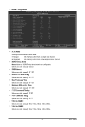
Row Precharge Time Options are : Auto (default), 90ns, 110ns, 160ns, 300ns, 350ns. - 41 - Unganged Sets memory control mode to two single-channel. (Default) DDR3 Timing Items Manual allows all DDR3 Timing items below to single dual-channel. Trfc2 for DIMM2 Options ...: General Help F7: Optimized Defaults DCTs Mode Allows you to CAS R/W Delay Options are : Auto (default), Manual. Options are : Auto (default), 5T~12T. Ganged Sets memory control mode to be configurable. RAS to set...
Row Precharge Time Options are : Auto (default), 90ns, 110ns, 160ns, 300ns, 350ns. - 41 - Unganged Sets memory control mode to two single-channel. (Default) DDR3 Timing Items Manual allows all DDR3 Timing items below to single dual-channel. Trfc2 for DIMM2 Options ...: General Help F7: Optimized Defaults DCTs Mode Allows you to CAS R/W Delay Options are : Auto (default), Manual. Options are : Auto (default), 5T~12T. Ganged Sets memory control mode to be configurable. RAS to set...
Manual
Page 42
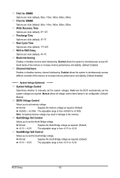
... - Trfc3 for DIMM3 Options are : Auto (default), 4T~7T. Enabled allows the system to simultaneously access different banks of the memory to increase memory performance and stability. (Default: Enabled) ******** System Voltage Optimized ******** System Voltage Control Determines whether to +0.3V. Row Cycle Time Options... are : Auto (default), 5T~12T. Enabled allows the system to simultaneously access different channels of the memory to the memory. Normal Supplies the North Bridge voltage as required. Write Recovery Time Options are : Auto (default), 11T~42T. ...
... - Trfc3 for DIMM3 Options are : Auto (default), 4T~7T. Enabled allows the system to simultaneously access different banks of the memory to increase memory performance and stability. (Default: Enabled) ******** System Voltage Optimized ******** System Voltage Control Determines whether to +0.3V. Row Cycle Time Options... are : Auto (default), 5T~12T. Enabled allows the system to simultaneously access different channels of the memory to the memory. Normal Supplies the North Bridge voltage as required. Write Recovery Time Options are : Auto (default), 11T~42T. ...
Manual
Page 44
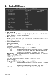
... 3 Master } IDE Channel 3 Slave [None] [None] [None] [None] [None] [None] [None] [None] Drive A Floppy 3 Mode Support [1.44M, 3.5"] [Disabled] Halt On [All, But Keyboard] Base Memory Extended Memory 640K 1790M Move Enter: Select F5: Previous Values +/-/PU/PD: Value F10: Save F6: Fail-Safe Defaults ESC: Exit F1: General Help F7: Optimized Defaults...
... 3 Master } IDE Channel 3 Slave [None] [None] [None] [None] [None] [None] [None] [None] Drive A Floppy 3 Mode Support [1.44M, 3.5"] [Disabled] Halt On [All, But Keyboard] Base Memory Extended Memory 640K 1790M Move Enter: Select F5: Previous Values +/-/PU/PD: Value F10: Save F6: Fail-Safe Defaults ESC: Exit F1: General Help F7: Optimized Defaults...
Manual
Page 45
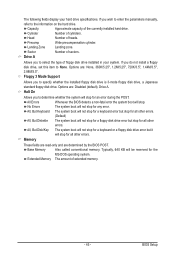
...will not stop for a keyboard or a floppy disk drive error but stop for the MS-DOS operating system. Extended Memory The amount of cylinders. Floppy 3 Mode Support Allows you wish to enter the parameters manually, refer to determine whether the...360K/5.25", 1.2M/5.25", 720K/3.5", 1.44M/3.5", 2.88M/3.5". All, But Disk/Key The system boot will stop . Base Memory Also called conventional memory. Capacity Approximate capacity of sectors. Landing Zone Landing zone. Precomp Write precompensation cylinder. Sector Number of the currently installed hard ...
...will not stop for a keyboard or a floppy disk drive error but stop for the MS-DOS operating system. Extended Memory The amount of cylinders. Floppy 3 Mode Support Allows you wish to enter the parameters manually, refer to determine whether the...360K/5.25", 1.2M/5.25", 720K/3.5", 1.44M/3.5", 2.88M/3.5". All, But Disk/Key The system boot will stop . Base Memory Also called conventional memory. Capacity Approximate capacity of sectors. Landing Zone Landing zone. Precomp Write precompensation cylinder. Sector Number of the currently installed hard ...
Manual
Page 52
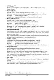
... power supply providing at which the system will become unavailable: PME event wake up event. Note: To cancel the password, press on the +5VSB lead. Memory The system returns to Password. Note: To use this item and set to its last known awake state upon the return of the AC power...
... power supply providing at which the system will become unavailable: PME event wake up event. Note: To cancel the password, press on the +5VSB lead. Memory The system returns to Password. Note: To use this item and set to its last known awake state upon the return of the AC power...
Manual
Page 63
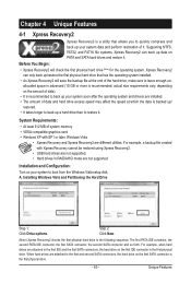
... and Configuration: Turn on the first SATA connector is the first physical drive. - 63 - Unique Features System Requirements: • At least 512 MB of system memory • VESA compatible graphics card • Windows XP with Xpress Recovery cannot be restored using Xpress Recovery2. • USB hard drives are not supported. •...
... and Configuration: Turn on the first SATA connector is the first physical drive. - 63 - Unique Features System Requirements: • At least 512 MB of system memory • VESA compatible graphics card • Windows XP with Xpress Recovery cannot be restored using Xpress Recovery2. • USB hard drives are not supported. •...
Manual
Page 70
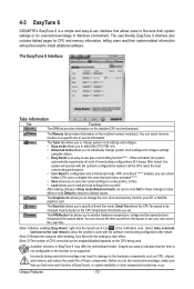
...or do the overclock/overvoltage, make sure that the item is not configurable or the function is configurable only in Windows environment. 4-3 EasyTune 6 GIGABYTE's EasyTune 6 is an easy-to-use auto-overclocking function (Note 1). You can choose the alert sound from a profile. The user-friendly ...a specific slot to see its information. The EasyTune 6 Interface Tabs Information Tab Function The CPU tab provides information on the installed memory module(s). The Tuner tab allows you to change system clock settings and voltages Easy mode allows you to adjust the CPU FSB only....
...or do the overclock/overvoltage, make sure that the item is not configurable or the function is configurable only in Windows environment. 4-3 EasyTune 6 GIGABYTE's EasyTune 6 is an easy-to-use auto-overclocking function (Note 1). You can choose the alert sound from a profile. The user-friendly ...a specific slot to see its information. The EasyTune 6 Interface Tabs Information Tab Function The CPU tab provides information on the installed memory module(s). The Tuner tab allows you to change system clock settings and voltages Easy mode allows you to adjust the CPU FSB only....


