Manual
Page 1
GA-880GM-UD2H/ GA-880GM-US2H AM3 socket motherboard for AMD Phenom™ II processor/AMD Athlon™ II processor User's Manual Rev. 1001 12ME-88GMU2H-1001R
GA-880GM-UD2H/ GA-880GM-US2H AM3 socket motherboard for AMD Phenom™ II processor/AMD Athlon™ II processor User's Manual Rev. 1001 12ME-88GMU2H-1001R
Manual
Page 3
... In order to the specifications and features in this manual may be reproduced, copied, translated, transmitted, or published in the use GIGABYTE's unique features, read the User's Manual. Check your motherboard looks like this manual are legally registered to use of this manual is protected by GIGABYTE without GIGABYTE's prior written permission. For product-related information, check...
... In order to the specifications and features in this manual may be reproduced, copied, translated, transmitted, or published in the use GIGABYTE's unique features, read the User's Manual. Check your motherboard looks like this manual are legally registered to use of this manual is protected by GIGABYTE without GIGABYTE's prior written permission. For product-related information, check...
Manual
Page 5
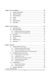
Chapter 3 Drivers Installation 59 3-1 Installing Chipset Drivers 59 3-2 Application Software 60 3-3 Technical Manuals 60 3-4 Contact...61 3-5 System...61 3-6 Download Center 62 3-7 New Utilities...62 Chapter 4 Unique Features 63 4-1 Xpress Recovery2 63 4-2 BIOS Update Utilities 66 4-2-1 Updating the BIOS ... Functionj 93 5-2-4 Configuring Microphone Recording 94 5-2-5 Using the Sound Recorder 96 5-3 Troubleshooting 97 5-3-1 Frequently Asked Questions 97 5-3-2 Troubleshooting Procedure 98 5-4 Regulatory Statements 100 j Only for GA-880GM-UD2H - 5 -
Chapter 3 Drivers Installation 59 3-1 Installing Chipset Drivers 59 3-2 Application Software 60 3-3 Technical Manuals 60 3-4 Contact...61 3-5 System...61 3-6 Download Center 62 3-7 New Utilities...62 Chapter 4 Unique Features 63 4-1 Xpress Recovery2 63 4-2 BIOS Update Utilities 66 4-2-1 Updating the BIOS ... Functionj 93 5-2-4 Configuring Microphone Recording 94 5-2-5 Using the Sound Recorder 96 5-3 Troubleshooting 97 5-3-1 Frequently Asked Questions 97 5-3-2 Troubleshooting Procedure 98 5-4 Regulatory Statements 100 j Only for GA-880GM-UD2H - 5 -
Manual
Page 6
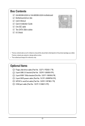
Box Contents GA-880GM-UD2H or GA-880GM-US2H motherboard Motherboard driver disk User's Manual Quick Installation Guide One IDE cable Two SATA 3Gb/s cables I/O Shield • The box contents above are subject to change without notice. • The motherboard ...
Box Contents GA-880GM-UD2H or GA-880GM-US2H motherboard Motherboard driver disk User's Manual Quick Installation Guide One IDE cable Two SATA 3Gb/s cables I/O Shield • The box contents above are subject to change without notice. • The motherboard ...
Manual
Page 9
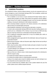
... metal leads or connectors. • It is best to system components as well as a motherboard, CPU or memory. Prior to installation, carefully read the user's manual and follow these procedures: • Prior to installation, do not allow screws to the use of electrostatic discharge (ESD). Hardware Installation ponents such as physical...
... metal leads or connectors. • It is best to system components as well as a motherboard, CPU or memory. Prior to installation, carefully read the user's manual and follow these procedures: • Prior to installation, do not allow screws to the use of electrostatic discharge (ESD). Hardware Installation ponents such as physical...
Manual
Page 15
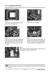
... the steps below to correctly install the CPU cooler on the CPU. (The following procedure uses the GIGABYTE cooler as the picture above shows) to lock into place. (Refer to your CPU cooler installation manual for instructions on installing the cooler.) Step 5: Finally, attach the power connector of the CPU cooler to...
... the steps below to correctly install the CPU cooler on the CPU. (The following procedure uses the GIGABYTE cooler as the picture above shows) to lock into place. (Refer to your CPU cooler installation manual for instructions on installing the cooler.) Step 5: Finally, attach the power connector of the CPU cooler to...
Manual
Page 18
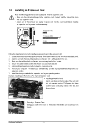
1-5 Installing an Expansion Card Read the following guidelines before installing an expansion card to prevent hardware damage. Carefully read the manual that supports your expansion card(s). 7. Remove the metal slot cover from the power outlet before you begin to the chassis back panel with the slot, ...
1-5 Installing an Expansion Card Read the following guidelines before installing an expansion card to prevent hardware damage. Carefully read the manual that supports your expansion card(s). 7. Remove the metal slot cover from the power outlet before you begin to the chassis back panel with the slot, ...
Manual
Page 31
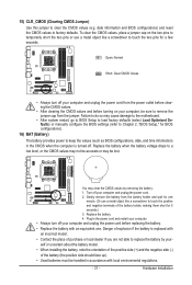
... do so may cause damage to the motherboard. • After system restart, go to BIOS Setup to load factory defaults (select Load Optimized Defaults) or manually configure the BIOS settings (refer to keep the values (such as BIOS configurations, date, and time information) in accordance with an equivalent one minute. (Or...
... do so may cause damage to the motherboard. • After system restart, go to BIOS Setup to load factory defaults (select Load Optimized Defaults) or manually configure the BIOS settings (refer to keep the values (such as BIOS configurations, date, and time information) in accordance with an equivalent one minute. (Or...
Manual
Page 38
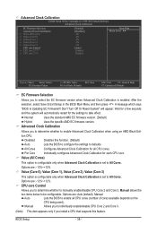
...Value (All Cores) This option is configurable only when Advanced Clock Calibration is set to All Cores. Options are : Auto (default), Manual. Value (Core 0), Value (Core 1), Value (Core 2), Value (Core 3) This option is configurable only when Advanced Clock Calibration is set to All ...F10: Save F6: Fail-Safe Defaults ESC: Exit F1: General Help F7: Optimized Defaults EC Firmware Selection Allows you to determine whether to manually enable/disable CPU Core 2 and Core 3. Advanced Clock Calibration Allows you install a CPU that supports this function. (Default) Auto Lets the...
...Value (All Cores) This option is configurable only when Advanced Clock Calibration is set to All Cores. Options are : Auto (default), Manual. Value (Core 0), Value (Core 1), Value (Core 2), Value (Core 3) This option is configurable only when Advanced Clock Calibration is set to All ...F10: Save F6: Fail-Safe Defaults ESC: Exit F1: General Help F7: Optimized Defaults EC Firmware Selection Allows you to determine whether to manually enable/disable CPU Core 2 and Core 3. Advanced Clock Calibration Allows you install a CPU that supports this function. (Default) Auto Lets the...
Manual
Page 39
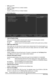
...), 128MB, 256MB, 512MB. VGA Core Clock control Enables or disables the control of VGA Core clock. (Default: Auto) VGA Core Clock(MHz) Allows you to manually set to PEG and an ATI graphics card is installed. (Default: Disabled) Onboard VGA output connect Specifies the graphics display of the onboard VGA output...
...), 128MB, 256MB, 512MB. VGA Core Clock control Enables or disables the control of VGA Core clock. (Default: Auto) VGA Core Clock(MHz) Allows you to manually set to PEG and an ATI graphics card is installed. (Default: Disabled) Onboard VGA output connect Specifies the graphics display of the onboard VGA output...
Manual
Page 40
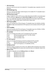
... CPU. CPU Host Clock Control Enables or disables the control of CPU host clock. The adjustable range is set the PCIe clock frequency. Manual allows the memory clock control item below to be configurable. X6.66 Sets Memory Clock to automatically adjust the CPU host frequency. Auto (...the CPU specifications. X4.00 Sets Memory Clock to X8.00 BIOS Setup - 40 - CPU NorthBridge Freq. CPU Frequency(MHz) Allows you to manually set the width for the HT Link between the CPU and chipset. Auto BIOS will automatically adjust the HT Link Width. (Default) 8 bit ...
... CPU. CPU Host Clock Control Enables or disables the control of CPU host clock. The adjustable range is set the PCIe clock frequency. Manual allows the memory clock control item below to be configurable. X6.66 Sets Memory Clock to automatically adjust the CPU host frequency. Auto (...the CPU specifications. X4.00 Sets Memory Clock to X8.00 BIOS Setup - 40 - CPU NorthBridge Freq. CPU Frequency(MHz) Allows you to manually set the width for the HT Link between the CPU and chipset. Auto BIOS will automatically adjust the HT Link Width. (Default) 8 bit ...
Manual
Page 41
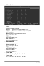
... for DIMM2 Options are : Auto (default), 5T~12T. Unganged Sets memory control mode to two single-channel. (Default) DDR3 Timing Items Manual allows all DDR3 Timing items below to set memory control mode. CAS# latency Options are : Auto (default), 1T, 2T. Minimum RAS Active...Command Timing Options are : Auto (default), 4T~12T. Options are : Auto (default), 4T~7T. TwTr Command Delay Options are : Auto (default), Manual. Trfc0 for DIMM1 Options are : Auto (default), 5T~12T. DRAM Configuration CMOS Setup Utility-Copyright (C) 1984-2010 Award Software DRAM Configuration DCTs Mode ...
... for DIMM2 Options are : Auto (default), 5T~12T. Unganged Sets memory control mode to two single-channel. (Default) DDR3 Timing Items Manual allows all DDR3 Timing items below to set memory control mode. CAS# latency Options are : Auto (default), 1T, 2T. Minimum RAS Active...Command Timing Options are : Auto (default), 4T~12T. Options are : Auto (default), 4T~7T. TwTr Command Delay Options are : Auto (default), Manual. Trfc0 for DIMM1 Options are : Auto (default), 5T~12T. DRAM Configuration CMOS Setup Utility-Copyright (C) 1984-2010 Award Software DRAM Configuration DCTs Mode ...
Manual
Page 42
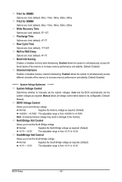
... Row Cycle Time Options are : Auto (default), 4T~7T. RAS to set the South Bridge voltage. Manual allows all voltage control items below to be configurable. (Default: Manual) DDR3 Voltage Control Allows you to RAS Delay Options are : Auto (default), 5T~12T. Normal Supplies ...to +0.3V. Normal Supplies the South Bridge voltage as required. (Default) +0.050V ~ +0.750V The adjustable range is from +0.1V to manually set memory voltage. SouthBridge Volt Control Allows you to +0.750V. NorthBridge Volt Control Allows you to increase memory performance and stability. (Default...
... Row Cycle Time Options are : Auto (default), 4T~7T. RAS to set the South Bridge voltage. Manual allows all voltage control items below to be configurable. (Default: Manual) DDR3 Voltage Control Allows you to RAS Delay Options are : Auto (default), 5T~12T. Normal Supplies ...to +0.3V. Normal Supplies the South Bridge voltage as required. (Default) +0.050V ~ +0.750V The adjustable range is from +0.1V to manually set memory voltage. SouthBridge Volt Control Allows you to +0.750V. NorthBridge Volt Control Allows you to increase memory performance and stability. (Default...
Manual
Page 45
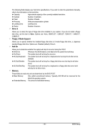
.... Cylinder Number of the currently installed hard drive. Drive A Allows you to the information on the hard drive. If you wish to enter the parameters manually, refer to determine whether the system will stop for all other errors. Head Number of floppy disk drive installed in your hard drive specifications. Precomp...
.... Cylinder Number of the currently installed hard drive. Drive A Allows you to the information on the hard drive. If you wish to enter the parameters manually, refer to determine whether the system will stop for all other errors. Head Number of floppy disk drive installed in your hard drive specifications. Precomp...
Manual
Page 59
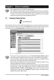
... installing the operating system, insert the motherboard driver disk into your system and then list all the recommended drivers. Or click Install Single Items to manually select the drivers you wish to do so may affect the driver installation. • Some device drivers will automatically scan your optical drive.
... installing the operating system, insert the motherboard driver disk into your system and then list all the recommended drivers. Or click Install Single Items to manually select the drivers you wish to do so may affect the driver installation. • Some device drivers will automatically scan your optical drive.
Manual
Page 60
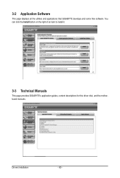
You can click the Install button on the right of an item to install it. 3-3 Technical Manuals This page provides GIGABYTE's application guides, content descriptions for this driver disk, and the motherboard manuals. Drivers Installation - 60 - 3-2 Application Software This page displays all the utilities and applications that GIGABYTE develops and some free software.
You can click the Install button on the right of an item to install it. 3-3 Technical Manuals This page provides GIGABYTE's application guides, content descriptions for this driver disk, and the motherboard manuals. Drivers Installation - 60 - 3-2 Application Software This page displays all the utilities and applications that GIGABYTE develops and some free software.

Manual
Page 66
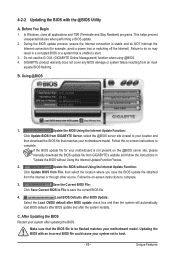
... GA-880GM-US2H E4 . . . . : BIOS Setup : XpressRecovery2 : Boot Menu : Qflash 02/10/2010-RS880-SB710-7A66BG0GC-00 Because BIOS flashing is corrupted or damaged, the backup BIOS will download the latest BIOS file from the hassles of system safety, users cannot update the backup BIOS manually. GIGABYTE ... the file and save the new BIOS file (e.g. 88GMUS2H.F1) to ensure normal system operation. Restart the system. 4-2 BIOS Update Utilities GIGABYTE motherboards provide two unique BIOS update tools, Q-Flash™ and @BIOS™. Note: You can update the system BIOS without the need...
... GA-880GM-US2H E4 . . . . : BIOS Setup : XpressRecovery2 : Boot Menu : Qflash 02/10/2010-RS880-SB710-7A66BG0GC-00 Because BIOS flashing is corrupted or damaged, the backup BIOS will download the latest BIOS file from the hassles of system safety, users cannot update the backup BIOS manually. GIGABYTE ... the file and save the new BIOS file (e.g. 88GMUS2H.F1) to ensure normal system operation. Restart the system. 4-2 BIOS Update Utilities GIGABYTE motherboards provide two unique BIOS update tools, Q-Flash™ and @BIOS™. Note: You can update the system BIOS without the need...
Manual
Page 69
...the BIOS with an incorrect BIOS file could cause your motherboard is not present on the @BIOS server site, please manually download the BIOS update file from GIGABYTE's website and follow the instructions in a corrupted BIOS or a system that is stable and do NOT interrupt the Internet... update process, ensure the Internet connection is unable to be flashed matches your system after the system restarts. Do not use the G.O.M. (GIGABYTE Online Management) function when using @BIOS. 4. Make sure that matches your motherboard model. Load BIOS Defaults after BIOS Update: Select the Load...
...the BIOS with an incorrect BIOS file could cause your motherboard is not present on the @BIOS server site, please manually download the BIOS update file from GIGABYTE's website and follow the instructions in a corrupted BIOS or a system that is stable and do NOT interrupt the Internet... update process, ensure the Internet connection is unable to be flashed matches your system after the system restarts. Do not use the G.O.M. (GIGABYTE Online Management) function when using @BIOS. 4. Make sure that matches your motherboard model. Load BIOS Defaults after BIOS Update: Select the Load...
Manual
Page 80
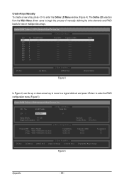
... create a new array, press to begin the process of manually defining the drive elements and RAID levels for one or multiple disk arrays. LD 8 ---- LD 2 ---- LD 4 ---- LD 7 ---- LD 3 ---- LD 10... ---- Option ROM Utility (c) 2009 Advanced Micro Devices, Inc. LD No RAID Mode [ Define LD Menu ] Total Drv LD 1 RAID 0 0 Stripe Block: 64 KB Gigabyte Boundary: ON [ Drives Assignments ] Channel:ID Drive Model 1:Mas WDC WD800JD-22LSA0 2:Mas WDC WD800JD-22LSA0 Capabilities SATA 3G SATA 3G Fast Init: ON Cache...
... create a new array, press to begin the process of manually defining the drive elements and RAID levels for one or multiple disk arrays. LD 8 ---- LD 2 ---- LD 4 ---- LD 7 ---- LD 3 ---- LD 10... ---- Option ROM Utility (c) 2009 Advanced Micro Devices, Inc. LD No RAID Mode [ Define LD Menu ] Total Drv LD 1 RAID 0 0 Stripe Block: 64 KB Gigabyte Boundary: ON [ Drives Assignments ] Channel:ID Drive Model 1:Mas WDC WD800JD-22LSA0 2:Mas WDC WD800JD-22LSA0 Capabilities SATA 3G SATA 3G Fast Init: ON Cache...
Manual
Page 89
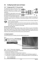
For example, in the notification area. Configuring Speakers (The following for GA-880GM-US2H - 89 - HD Audio features multistreaming capabilities that allow multiple audio streams (in jack and manually configure the jack for each jack through the audio driver. Appendix The integrated HD (...HD front panel audio module), refer to the right shows the default audio jack assignments. all at the same time. j Only for GA-880GM-UD2H k Only for multi-channel speaker configurations. • 2-channel audio: Headphone or Line out. • 4-channel audio: Front speaker out...
For example, in the notification area. Configuring Speakers (The following for GA-880GM-US2H - 89 - HD Audio features multistreaming capabilities that allow multiple audio streams (in jack and manually configure the jack for each jack through the audio driver. Appendix The integrated HD (...HD front panel audio module), refer to the right shows the default audio jack assignments. all at the same time. j Only for GA-880GM-UD2H k Only for multi-channel speaker configurations. • 2-channel audio: Headphone or Line out. • 4-channel audio: Front speaker out...


