Manual
Page 1
GA-880GM-UD2H/ GA-880GM-US2H AM3 socket motherboard for AMD Phenom™ II processor/AMD Athlon™ II processor User's Manual Rev. 1001 12ME-88GMU2H-1001R
GA-880GM-UD2H/ GA-880GM-US2H AM3 socket motherboard for AMD Phenom™ II processor/AMD Athlon™ II processor User's Manual Rev. 1001 12ME-88GMU2H-1001R
Manual
Page 2
Motherboard GA-880GM-UD2H/GA-880GM-US2H Mar. 5, 2010 Motherboard GA-880GM-UD2H/ GA-880GM-US2H Mar. 5, 2010
Motherboard GA-880GM-UD2H/GA-880GM-US2H Mar. 5, 2010 Motherboard GA-880GM-UD2H/ GA-880GM-US2H Mar. 5, 2010
Manual
Page 3
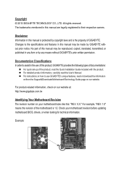
... 1.0. Copyright © 2010 GIGA-BYTE TECHNOLOGY CO., LTD. For product-related information, check on our website at: http://www.gigabyte.com.tw Identifying Your Motherboard Revision The revision number on our website. Check your motherboard looks like this manual may be reproduced, copied, translated, transmitted, or published in this manual is protected by...
... 1.0. Copyright © 2010 GIGA-BYTE TECHNOLOGY CO., LTD. For product-related information, check on our website at: http://www.gigabyte.com.tw Identifying Your Motherboard Revision The revision number on our website. Check your motherboard looks like this manual may be reproduced, copied, translated, transmitted, or published in this manual is protected by...
Manual
Page 4
Table of Contents Box Contents...6 Optional Items...6 GA-880GM-UD2H/GA-880GM-US2H Motherboard Layout 7 GA-880GM-UD2H/GA-880GM-US2H Motherboard Block Diagram 8 Chapter 1 Hardware Installation 9 1-1 Installation Precautions 9 1-2 Product Specifications 10 1-3 Installing the CPU and CPU Cooler 13 1-3-1 Installing the CPU 13 1-3-2 Installing the CPU Cooler ...
Table of Contents Box Contents...6 Optional Items...6 GA-880GM-UD2H/GA-880GM-US2H Motherboard Layout 7 GA-880GM-UD2H/GA-880GM-US2H Motherboard Block Diagram 8 Chapter 1 Hardware Installation 9 1-1 Installation Precautions 9 1-2 Product Specifications 10 1-3 Installing the CPU and CPU Cooler 13 1-3-1 Installing the CPU 13 1-3-2 Installing the CPU Cooler ...
Manual
Page 6
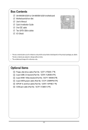
The box contents are for reference only. Box Contents GA-880GM-UD2H or GA-880GM-US2H motherboard Motherboard driver disk User's Manual Quick Installation Guide One IDE cable Two SATA 3Gb/s cables I/O Shield • The box contents above are subject to change without notice. • The motherboard image is for reference only and the actual items shall depend on...
The box contents are for reference only. Box Contents GA-880GM-UD2H or GA-880GM-US2H motherboard Motherboard driver disk User's Manual Quick Installation Guide One IDE cable Two SATA 3Gb/s cables I/O Shield • The box contents above are subject to change without notice. • The motherboard image is for reference only and the actual items shall depend on...
Manual
Page 7
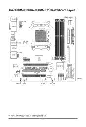
GA-880GM-UD2H/GA-880GM-US2H Motherboard Layout KB_MS_USB ATX_12V_2X4 VGA_DVI Socket AM3 M_BIOS B_BIOS ATX FDD iTE IT8720 HDMI OPTICAL ESATA_1394_USB CPU_FAN USB_LAN F_AUDIO AUDIO PCIEX1 AMD 880G PCIEX16 RTL8111D CD_IN CODEC PCI1 GA-880GM-UD2H/GA-880GM-US2H BAT CLR_CMOS PCI2 TSB43AB23 DDR3_1 DDR3_2 DDR3_4 IDE DDR3_3 AMD SB710 SATA2_4 SPDIF_IO COM F_1394_1 SYS_FAN F_USB1 F_USB2 F_USB3 SATA2_1 SATA2_3 SATA2_0 SATA2_2 F_PANEL "*" The GA-880GM-UD2H adopts All-Solid Capacitor design. - 7 -
GA-880GM-UD2H/GA-880GM-US2H Motherboard Layout KB_MS_USB ATX_12V_2X4 VGA_DVI Socket AM3 M_BIOS B_BIOS ATX FDD iTE IT8720 HDMI OPTICAL ESATA_1394_USB CPU_FAN USB_LAN F_AUDIO AUDIO PCIEX1 AMD 880G PCIEX16 RTL8111D CD_IN CODEC PCI1 GA-880GM-UD2H/GA-880GM-US2H BAT CLR_CMOS PCI2 TSB43AB23 DDR3_1 DDR3_2 DDR3_4 IDE DDR3_3 AMD SB710 SATA2_4 SPDIF_IO COM F_1394_1 SYS_FAN F_USB1 F_USB2 F_USB3 SATA2_1 SATA2_3 SATA2_0 SATA2_2 F_PANEL "*" The GA-880GM-UD2H adopts All-Solid Capacitor design. - 7 -
Manual
Page 8
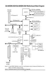
GA-880GM-UD2H/GA-880GM-US2H Motherboard Block Diagram PCIe CLK (100 MHz) 1 PCI Express x16 PCI Express x16 PCI Express Bus x1 x1 PCIe CLK (100 MHz) RTL8111D RJ45 1 PCI Express ...
GA-880GM-UD2H/GA-880GM-US2H Motherboard Block Diagram PCIe CLK (100 MHz) 1 PCI Express x16 PCI Express x16 PCI Express Bus x1 x1 PCIe CLK (100 MHz) RTL8111D RJ45 1 PCI Express ...
Manual
Page 9
.... • When connecting hardware components to the internal connectors on the computer power during the installation process can become damaged as a motherboard, CPU or memory. These stickers are required for warranty validation. • Always remove the AC power by your dealer. Hardware Installation... or have it on top of your hands dry and first touch a metal object to eliminate static electricity. • Prior to installing the motherboard, please have a problem related to the use of the product, please consult a certified computer technician. - 9 - If you are uncertain ...
.... • When connecting hardware components to the internal connectors on the computer power during the installation process can become damaged as a motherboard, CPU or memory. These stickers are required for warranty validation. • Always remove the AC power by your dealer. Hardware Installation... or have it on top of your hands dry and first touch a metal object to eliminate static electricity. • Prior to installing the motherboard, please have a problem related to the use of the product, please consult a certified computer technician. - 9 - If you are uncertain ...
Manual
Page 12
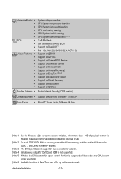
... CPU/system fan speed control function is supported will depend on the CPU/system cooler you install. (Note 6) Available functions in EasyTune may differ by motherboard model. Hardware Installation - 12 -
... CPU/system fan speed control function is supported will depend on the CPU/system cooler you install. (Note 6) Available functions in EasyTune may differ by motherboard model. Hardware Installation - 12 -
Manual
Page 13
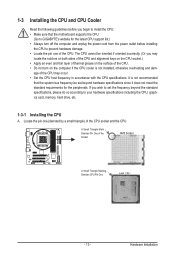
...- Locate the pin one of the CPU. • Do not turn on the surface of the CPU. It is not recommended that the motherboard supports the CPU. (Go to GIGABYTE's website for the peripherals. If you may occur. • Set the CPU host frequency in accordance with the CPU specifications. age of...
...- Locate the pin one of the CPU. • Do not turn on the surface of the CPU. It is not recommended that the motherboard supports the CPU. (Go to GIGABYTE's website for the peripherals. If you may occur. • Set the CPU host frequency in accordance with the CPU specifications. age of...
Manual
Page 14
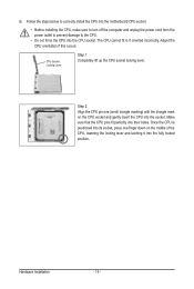
... socket. CPU Socket Locking Lever Step 1: Completely lift up the CPU socket locking lever. Follow the steps below to correctly install the CPU into the motherboard CPU socket. • Before installing the CPU, make sure to turn off the computer and unplug the power cord from the power outlet to prevent...
... socket. CPU Socket Locking Lever Step 1: Completely lift up the CPU socket locking lever. Follow the steps below to correctly install the CPU into the motherboard CPU socket. • Before installing the CPU, make sure to turn off the computer and unplug the power cord from the power outlet to prevent...
Manual
Page 15
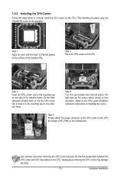
...Step 3: Hook the CPU cooler clip to the mounting lug on one side of the CPU cooler to the CPU fan header (CPU_FAN) on the motherboard. Step 2: Place the CPU cooler on the retention frame. Step 4: Turn the cam handle from the left side to the right side (as the...Hardware Installation 1-3-2 Installing the CPU Cooler Follow the steps below to correctly install the CPU cooler on the CPU. (The following procedure uses the GIGABYTE cooler as the picture above shows) to lock into place. (Refer to your CPU cooler installation manual for instructions on the surface of the ...
...Step 3: Hook the CPU cooler clip to the mounting lug on one side of the CPU cooler to the CPU fan header (CPU_FAN) on the motherboard. Step 2: Place the CPU cooler on the retention frame. Step 4: Turn the cam handle from the left side to the right side (as the...Hardware Installation 1-3-2 Installing the CPU Cooler Follow the steps below to correctly install the CPU cooler on the CPU. (The following procedure uses the GIGABYTE cooler as the picture above shows) to lock into place. (Refer to your CPU cooler installation manual for instructions on the surface of the ...
Manual
Page 16
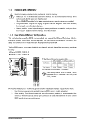
... Memory Configurations Table DDR3_1 DDR3_2 DDR3_3 DDR3_4 Two Modules DS/SS DS/SS - - - - - - - - It is recommended that the motherboard supports the memory. When enabling Dual Channel mode with two or four memory modules, it is installed. 2. If you are divided into two channels...direction. The four DDR3 memory sockets are unable to GIGABYTE's website for optimum performance. A memory module can be used . (Go to insert the memory, switch the direction. 1-4-1 Dual Channel Memory Configuration This motherboard provides four DDR3 memory sockets and supports Dual Channel ...
... Memory Configurations Table DDR3_1 DDR3_2 DDR3_3 DDR3_4 Two Modules DS/SS DS/SS - - - - - - - - It is recommended that the motherboard supports the memory. When enabling Dual Channel mode with two or four memory modules, it is installed. 2. If you are divided into two channels...direction. The four DDR3 memory sockets are unable to GIGABYTE's website for optimum performance. A memory module can be used . (Go to insert the memory, switch the direction. 1-4-1 Dual Channel Memory Configuration This motherboard provides four DDR3 memory sockets and supports Dual Channel ...
Manual
Page 17
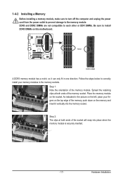
..., make sure to turn off the computer and unplug the power cord from the power outlet to prevent damage to install DDR3 DIMMs on this motherboard.
..., make sure to turn off the computer and unplug the power cord from the power outlet to prevent damage to install DDR3 DIMMs on this motherboard.
Manual
Page 18
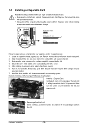
... seated in the slot. 3. Remove the metal slot cover from the power outlet before you begin to install an expansion card: • Make sure the motherboard supports the expansion card. Align the card with a screw. 5. Make sure the card is fully inserted into the slot. 4. Example: Installing and Removing a PCI Express...
... seated in the slot. 3. Remove the metal slot cover from the power outlet before you begin to install an expansion card: • Make sure the motherboard supports the expansion card. Align the card with a screw. 5. Make sure the card is fully inserted into the slot. 4. Example: Installing and Removing a PCI Express...
Manual
Page 19
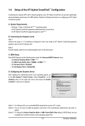
... Read the following items under the Advanced BIOS Features menu: - Set Surround View to OnChipVGA. Configuring the Graphics Driver After installing the motherboard driver in the operating system first. - 19 - System Requirements - Windows 7, Vista, or Windows XP (Note 1) operating system ... graphics card, ATI Hybrid CrossFireX can provide significantly advanced display performance for AMD platform. An ATI Hybrid CrossFireX-supported motherboard and correct driver - Step 2: Plug the display cable into the onboard graphics port on the upper left corner and...
... Read the following items under the Advanced BIOS Features menu: - Set Surround View to OnChipVGA. Configuring the Graphics Driver After installing the motherboard driver in the operating system first. - 19 - System Requirements - Windows 7, Vista, or Windows XP (Note 1) operating system ... graphics card, ATI Hybrid CrossFireX can provide significantly advanced display performance for AMD platform. An ATI Hybrid CrossFireX-supported motherboard and correct driver - Step 2: Plug the display cable into the onboard graphics port on the upper left corner and...
Manual
Page 21
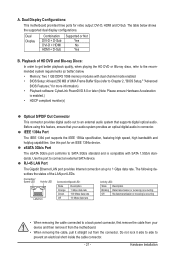
...The Gigabit Ethernet LAN port provides Internet connection at up to an external audio system that your device and then remove it from the motherboard. • When removing the cable, pull it side to side to SATA 3Gb/s standard and is compatible with dual channel mode ...a back panel connector, first remove the cable from your audio system provides an optical digital audio in connector. A. Dual Display Configurations: This motherboard provides three ports for an IEEE 1394a device. Before using this port for video output: DVI-D, HDMI and D-Sub. Connection/ Speed LED Activity...
...The Gigabit Ethernet LAN port provides Internet connection at up to an external audio system that your device and then remove it from the motherboard. • When removing the cable, pull it side to side to SATA 3Gb/s standard and is compatible with dual channel mode ...a back panel connector, first remove the cable from your audio system provides an optical digital audio in connector. A. Dual Display Configurations: This motherboard provides three ports for an IEEE 1394a device. Before using this port for video output: DVI-D, HDMI and D-Sub. Connection/ Speed LED Activity...
Manual
Page 23
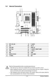
... 9) F_AUDIO 10) CD_IN 11) SPDIF_IO 12) F_USB1/F_USB2/F_USB3 13) F_1394_1 14) COM 15) CLR_CMOS 16) BAT Read the following guidelines before turning on the motherboard. - 23 - Unplug the power cord from the power outlet to prevent damage to the devices. • After installing the device and before connecting external devices...
... 9) F_AUDIO 10) CD_IN 11) SPDIF_IO 12) F_USB1/F_USB2/F_USB3 13) F_1394_1 14) COM 15) CLR_CMOS 16) BAT Read the following guidelines before turning on the motherboard. - 23 - Unplug the power cord from the power outlet to prevent damage to the devices. • After installing the device and before connecting external devices...
Manual
Page 24
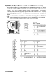
..., the computer will not start. The power connector possesses a foolproof design. If the 12V power connector is turned off and all the components on the motherboard.
..., the computer will not start. The power connector possesses a foolproof design. If the 12V power connector is turned off and all the components on the motherboard.
Manual
Page 25
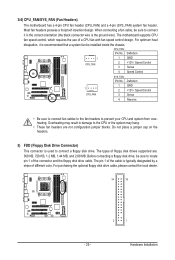
...the connector and the floppy disk drive cable. Before connecting a floppy disk drive, be installed inside the chassis. 3/4) CPU_FAN/SYS_FAN (Fan Headers) The motherboard has a 4-pin CPU fan header (CPU_FAN) and a 4-pin (SYS_FAN) system fan header. When connecting a fan cable, be sure to connect... ground wire). For purchasing the optional floppy disk drive cable, please contact the local dealer. 34 33 2 1 - 25 - The motherboard supports CPU fan speed control, which requires the use of floppy disk drives supported are not configuration jumper blocks. Most fan headers possess a...
...the connector and the floppy disk drive cable. Before connecting a floppy disk drive, be installed inside the chassis. 3/4) CPU_FAN/SYS_FAN (Fan Headers) The motherboard has a 4-pin CPU fan header (CPU_FAN) and a 4-pin (SYS_FAN) system fan header. When connecting a fan cable, be sure to connect... ground wire). For purchasing the optional floppy disk drive cable, please contact the local dealer. 34 33 2 1 - 25 - The motherboard supports CPU fan speed control, which requires the use of floppy disk drives supported are not configuration jumper blocks. Most fan headers possess a...


