Manual
Page 8
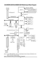
GA-880GM-UD2H/GA-880GM-US2H Motherboard Block Diagram PCIe CLK (100 MHz) 1 PCI Express x16 PCI Express x16 PCI Express Bus x1 x1 PCIe CLK (100 MHz) RTL8111D RJ45 1 PCI Express x1 LAN ATA-133/100/66/33 IDE Channel AM3 CPU CPU CLK+/- (200 MHz) DDR3 1800 (O.C.)/1333/1066 MHz (Note 1) Dual Channel Memory... Center/Subwoofer Speaker Out Side Speaker Out MIC Line Out Line In S/PDIF In S/PDIF Out 2 PCI PCI CLK (33 MHz) (Note 1) To reach DDR3 1800 MHz or above, you must install two memory modules and install them in the DDR3_3 and DDR3_4 memory sockets. (Note 2) Simultaneous output for DVD...
GA-880GM-UD2H/GA-880GM-US2H Motherboard Block Diagram PCIe CLK (100 MHz) 1 PCI Express x16 PCI Express x16 PCI Express Bus x1 x1 PCIe CLK (100 MHz) RTL8111D RJ45 1 PCI Express x1 LAN ATA-133/100/66/33 IDE Channel AM3 CPU CPU CLK+/- (200 MHz) DDR3 1800 (O.C.)/1333/1066 MHz (Note 1) Dual Channel Memory... Center/Subwoofer Speaker Out Side Speaker Out MIC Line Out Line In S/PDIF In S/PDIF Out 2 PCI PCI CLK (33 MHz) (Note 1) To reach DDR3 1800 MHz or above, you must install two memory modules and install them in the DDR3_3 and DDR3_4 memory sockets. (Note 2) Simultaneous output for DVD...
Manual
Page 10
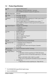
... sockets supporting up to 16 GB of system memory (Note 1) Dual channel memory architecture Support for DDR3 1800(O.C.)/1333/1066 MHz memory modules (Note 2) (Go to GIGABYTE's website for the latest supported memory speeds and memory modules.) Integrated in the North Bridge: - 1 x D-Sub port... Express x1 slot (All PCI Express slots conform to the PCI Express 2.0 standard 2 x PCI slots Multi-Graphics Support for GA-880GM-UD2H Hardware Installation - 10 - j Only for ATI Hybrid CrossFireX™ technology Technology Storage Interface South Bridge: - 5 x SATA...
... sockets supporting up to 16 GB of system memory (Note 1) Dual channel memory architecture Support for DDR3 1800(O.C.)/1333/1066 MHz memory modules (Note 2) (Go to GIGABYTE's website for the latest supported memory speeds and memory modules.) Integrated in the North Bridge: - 1 x D-Sub port... Express x1 slot (All PCI Express slots conform to the PCI Express 2.0 standard 2 x PCI slots Multi-Graphics Support for GA-880GM-UD2H Hardware Installation - 10 - j Only for ATI Hybrid CrossFireX™ technology Technology Storage Interface South Bridge: - 5 x SATA...
Manual
Page 12
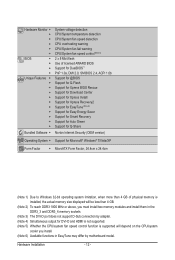
... operating system limitation, when more than 4 GB of physical memory is installed, the actual memory size displayed will be less than 4 GB. (Note 2) To reach DDR3 1800 MHz or above, you must install two memory modules and install them in the DDR3_3 and DDR3_4 memory sockets. (Note 3) The DVI-D port does...
... operating system limitation, when more than 4 GB of physical memory is installed, the actual memory size displayed will be less than 4 GB. (Note 2) To reach DDR3 1800 MHz or above, you must install two memory modules and install them in the DDR3_3 and DDR3_4 memory sockets. (Note 3) The DVI-D port does...
Manual
Page 16
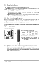
...the following guidelines before you are unable to insert the memory, switch the direction. 1-4-1 Dual Channel Memory Configuration This motherboard provides four DDR3 memory sockets and supports Dual Channel Technology. If you begin to CPU limitations, read the following : Channel 0: DDR3_1, DDR3_3 Channel ... detect the specifications and capacity of the same capacity, brand, speed, and chips be used . (Go to GIGABYTE's website for optimum performance. The four DDR3 memory sockets are to prevent hardware damage. • Memory modules have a foolproof design. After the memory is ...
...the following guidelines before you are unable to insert the memory, switch the direction. 1-4-1 Dual Channel Memory Configuration This motherboard provides four DDR3 memory sockets and supports Dual Channel Technology. If you begin to CPU limitations, read the following : Channel 0: DDR3_1, DDR3_3 Channel ... detect the specifications and capacity of the same capacity, brand, speed, and chips be used . (Go to GIGABYTE's website for optimum performance. The four DDR3 memory sockets are to prevent hardware damage. • Memory modules have a foolproof design. After the memory is ...
Manual
Page 17
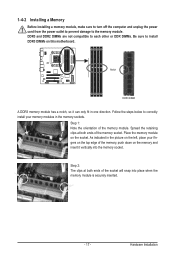
Spread the retaining clips at both ends of the memory, push down on the memory and insert it can only fit in the memory sockets. DDR3 and DDR2 DIMMs are not compatible to each other or DDR DIMMs. Be sure to the memory module. Step 1: Note the orientation of the socket... on the top edge of the memory socket. Place the memory module on the left, place your memory modules in one direction. Hardware Installation Notch DDR3 DIMM A DDR3 memory module has a notch, so it vertically into place when the memory module is securely inserted. - 17 - Step 2: The clips at both ends ...
Spread the retaining clips at both ends of the memory, push down on the memory and insert it can only fit in the memory sockets. DDR3 and DDR2 DIMMs are not compatible to each other or DDR DIMMs. Be sure to the memory module. Step 1: Note the orientation of the socket... on the top edge of the memory socket. Place the memory module on the left, place your memory modules in one direction. Hardware Installation Notch DDR3 DIMM A DDR3 memory module has a notch, so it vertically into place when the memory module is securely inserted. - 17 - Step 2: The clips at both ends ...
Manual
Page 21
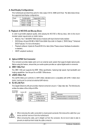
... is occurring • When removing the cable connected to prevent an electrical short inside the cable connector. - 21 - The table below . • Memory: Two 1 GB DDR3 1066 memory modules with SATA 1.5Gb/s standards. A. The following describes the states of UMA Frame Buffer Size (refer to Chapter 2, "BIOS Setup," "Advanced BIOS Features...
... is occurring • When removing the cable connected to prevent an electrical short inside the cable connector. - 21 - The table below . • Memory: Two 1 GB DDR3 1066 memory modules with SATA 1.5Gb/s standards. A. The following describes the states of UMA Frame Buffer Size (refer to Chapter 2, "BIOS Setup," "Advanced BIOS Features...
Manual
Page 37
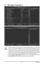
... x CPU Frequency(MHz) PCIE Clock(MHz) HT Link Width HT Link Frequency Set Memory Clock x Memory Clock } DRAM Configuration ******** System Voltage Optimized ******** System Voltage Control x DDR3 Voltage Control x NorthBridge Volt Control x SouthBridge Volt Control x CPU NB VID Control x CPU Voltage Control [Press Enter] [Press Enter] [Auto] 2800Mhz [Auto] 2000Mhz [Auto] 200...
... x CPU Frequency(MHz) PCIE Clock(MHz) HT Link Width HT Link Frequency Set Memory Clock x Memory Clock } DRAM Configuration ******** System Voltage Optimized ******** System Voltage Control x DDR3 Voltage Control x NorthBridge Volt Control x SouthBridge Volt Control x CPU NB VID Control x CPU Voltage Control [Press Enter] [Press Enter] [Auto] 2800Mhz [Auto] 2000Mhz [Auto] 200...
Manual
Page 41
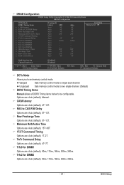
Unganged Sets memory control mode to two single-channel. (Default) DDR3 Timing Items Manual allows all DDR3 Timing items below to set memory control mode. Row Precharge Time Options are : Auto (default), 4T~7T. TwTr Command Delay Options are : Auto ..., 300ns, 350ns. Trfc0 for DIMM1 Options are : Auto (default), 1T, 2T. DRAM Configuration CMOS Setup Utility-Copyright (C) 1984-2010 Award Software DRAM Configuration DCTs Mode DDR3 Timing Items x CAS# latency x RAS to CAS R/W Delay x Row Precharge Time x Minimum RAS Active Time x 1T/2T Command Timing x TwTr Command Delay x...
Unganged Sets memory control mode to two single-channel. (Default) DDR3 Timing Items Manual allows all DDR3 Timing items below to set memory control mode. Row Precharge Time Options are : Auto (default), 4T~7T. TwTr Command Delay Options are : Auto ..., 300ns, 350ns. Trfc0 for DIMM1 Options are : Auto (default), 1T, 2T. DRAM Configuration CMOS Setup Utility-Copyright (C) 1984-2010 Award Software DRAM Configuration DCTs Mode DDR3 Timing Items x CAS# latency x RAS to CAS R/W Delay x Row Precharge Time x Minimum RAS Active Time x 1T/2T Command Timing x TwTr Command Delay x...
Manual
Page 42
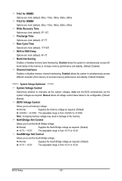
... the system voltages. NorthBridge Volt Control Allows you to +0.3V. BIOS Setup - 42 - Manual allows all voltage control items below to be configurable. (Default: Manual) DDR3 Voltage Control Allows you to manually set the South Bridge voltage. Normal Supplies the South Bridge voltage as required. (Default) +0.050V ~ +0.750V The adjustable range...
... the system voltages. NorthBridge Volt Control Allows you to +0.3V. BIOS Setup - 42 - Manual allows all voltage control items below to be configurable. (Default: Manual) DDR3 Voltage Control Allows you to manually set the South Bridge voltage. Normal Supplies the South Bridge voltage as required. (Default) +0.050V ~ +0.750V The adjustable range...
Manual
Page 54
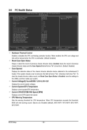
..." at next boot. (Default: Disabled) Case Opened Displays the detection status of previous chassis intrusion status. Current Voltage(V) Vcore/DDR3 1.5V/+3.3V/+12V Displays the current system voltages. Current System/CPU Temperature Displays current system/CPU temperature. 2-9 PC Health Status...Setup Utility-Copyright (C) 1984-2010 Award Software PC Health Status Hardware Thermal Control Reset Case Open Status Case Opened Vcore DDR3 1.5V +3.3V +12V Current System Temperature Current CPU Temperature Current CPU FAN Speed Current SYSTEM FAN Speed CPU Warning ...
..." at next boot. (Default: Disabled) Case Opened Displays the detection status of previous chassis intrusion status. Current Voltage(V) Vcore/DDR3 1.5V/+3.3V/+12V Displays the current system voltages. Current System/CPU Temperature Displays current system/CPU temperature. 2-9 PC Health Status...Setup Utility-Copyright (C) 1984-2010 Award Software PC Health Status Hardware Thermal Control Reset Case Open Status Case Opened Vcore DDR3 1.5V +3.3V +12V Current System Temperature Current CPU Temperature Current CPU FAN Speed Current SYSTEM FAN Speed CPU Warning ...


