
Hardware Owner's Manual
Page 10
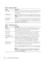
...for Accessing System Features Keystroke Description Enters the System Setup program. See "Running the System Diagnostics" on page 27. Initiates PXE boot. Enters the SAS Configuration Utility, which includes RAID configuration options. This keystroke allows you to run the system diagnostics. See "Using... Setup Program" on page 98. Enters the boot menu selection screen, allowing you enter the keystroke, allow the system to finish booting, and then restart your operating system begins to load before you to choose a boot device. If your system and try again. See...
...for Accessing System Features Keystroke Description Enters the System Setup program. See "Running the System Diagnostics" on page 27. Initiates PXE boot. Enters the SAS Configuration Utility, which includes RAID configuration options. This keystroke allows you to run the system diagnostics. See "Using... Setup Program" on page 98. Enters the boot menu selection screen, allowing you enter the keystroke, allow the system to finish booting, and then restart your operating system begins to load before you to choose a boot device. If your system and try again. See...
Hardware Owner's Manual
Page 15
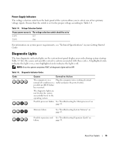
..., all diagnostic lights will be set to the proper voltage according to the operating system. The diagnostic lights are not lit after the system successfully boots to Table 1-4. Possible processor failure. See "Troubleshooting the Microprocessor" on ; Diagnostic Indicator Codes Code Causes Corrective Action The computer is on page 95. page 93...
..., all diagnostic lights will be set to the proper voltage according to the operating system. The diagnostic lights are not lit after the system successfully boots to Table 1-4. Possible processor failure. See "Troubleshooting the Microprocessor" on ; Diagnostic Indicator Codes Code Causes Corrective Action The computer is on page 95. page 93...

Hardware Owner's Manual
Page 18
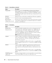
... are properly installed and operating correctly. See "Troubleshooting Expansion Cards" on page 86. See "Troubleshooting System Cooling Problems" on page 93. boot routine three consecutive times for a list of available memory to Off. Amount of system memory. Ensure that nothing is blocking the system was... while trying to 256MB. The OS Install Mode option in resolving this problem, please note this system have failed at booting this checkpoint and contact Dell Technical Support. See "Using the System Setup Program" on page 107. The system failed to On.
... are properly installed and operating correctly. See "Troubleshooting Expansion Cards" on page 86. See "Troubleshooting System Cooling Problems" on page 93. boot routine three consecutive times for a list of available memory to Off. Amount of system memory. Ensure that nothing is blocking the system was... while trying to 256MB. The OS Install Mode option in resolving this problem, please note this system have failed at booting this checkpoint and contact Dell Technical Support. See "Using the System Setup Program" on page 107. The system failed to On.

Hardware Owner's Manual
Page 21
... error Hard-disk controller failure The hard drive failed initialization. See "Troubleshooting the Keyboard" on page 27. Invalid configuration information - This message is unable to boot Insert a bootable diskette or CD. Run the system diagnostics. See "Using the System Setup Program" on page 81. See "Running the System Diagnostics" on page...
... error Hard-disk controller failure The hard drive failed initialization. See "Troubleshooting the Keyboard" on page 27. Invalid configuration information - This message is unable to boot Insert a bootable diskette or CD. Run the system diagnostics. See "Using the System Setup Program" on page 81. See "Running the System Diagnostics" on page...

Hardware Owner's Manual
Page 22
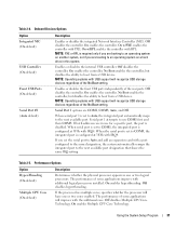
... word logic failure at address, read value expecting value A memory module might be faulty or improperly seated. Memory type or speed is your boot device, hard drive. See "Troubleshooting System Memory" on this system. Memory odd/even logic failure at address, read value expecting value Memory ... recorded in the system. See "Troubleshooting a NIC" on page 27. 22 About Your System Enter the System Setup program and verify the boot sequence information. If the in Restart the system. If the hard drive is not supported on page 87. Reinstall the memory modules and,...
... word logic failure at address, read value expecting value A memory module might be faulty or improperly seated. Memory type or speed is your boot device, hard drive. See "Troubleshooting System Memory" on this system. Memory odd/even logic failure at address, read value expecting value Memory ... recorded in the system. See "Troubleshooting a NIC" on page 27. 22 About Your System Enter the System Setup program and verify the boot sequence information. If the in Restart the system. If the hard drive is not supported on page 87. Reinstall the memory modules and,...

Hardware Owner's Manual
Page 23
...configuration be Run the system diagnostics. The diskette in the System Setup program might have been corrupted. If the message continues to boot Insert a diskette that has a bootable from a diskette that you want to restore system resources. If so, try again. Table 1-6....information. See malfunctioning. "Running the System Diagnostics" on hard-disk drive No timer tick interrupt Non-system disk or disk error Not a boot diskette Not enough memory or resources. If the problem persists, see "Troubleshooting a Diskette Drive" on page 89 or "Troubleshooting a Hard ...
...configuration be Run the system diagnostics. The diskette in the System Setup program might have been corrupted. If the message continues to boot Insert a diskette that has a bootable from a diskette that you want to restore system resources. If so, try again. Table 1-6....information. See malfunctioning. "Running the System Diagnostics" on hard-disk drive No timer tick interrupt Non-system disk or disk error Not a boot diskette Not enough memory or resources. If the problem persists, see "Troubleshooting a Diskette Drive" on page 89 or "Troubleshooting a Hard ...

Hardware Owner's Manual
Page 27
... the System Setup program, see the following message: = System Setup If your operating system begins to load before you press , allow the system to finish booting, and then restart your operating system. Using the System Setup Program After you set up your system, run the System Setup program to familiarize yourself...
... the System Setup program, see the following message: = System Setup If your operating system begins to load before you press , allow the system to finish booting, and then restart your operating system. Using the System Setup Program After you set up your system, run the System Setup program to familiarize yourself...
Hardware Owner's Manual
Page 30
... drive is using , Drive ID number, Capacity, whether the drive is ECC capable, single or dual rank, type, and organization for boot devices during system startup. Determines whether hard-drive errors for the internal diskette drive. Off does not report errors. Displays the types of ...used . This option also displays a table that the device can be used . System Options (continued) Option Memory Info PCI Info Date/Time Boot Sequence (Diskette drive default) Description Displays the amount of Installed Memory, Memory Speed, Memory Channel Mode, and a description of cards that the ...
... drive is using , Drive ID number, Capacity, whether the drive is ECC capable, single or dual rank, type, and organization for boot devices during system startup. Determines whether hard-drive errors for the internal diskette drive. Off does not report errors. Displays the types of ...used . This option also displays a table that the device can be used . System Options (continued) Option Memory Info PCI Info Date/Time Boot Sequence (Diskette drive default) Description Displays the amount of Installed Memory, Memory Speed, Memory Channel Mode, and a description of cards that the ...
Hardware Owner's Manual
Page 31
...system automatically remaps the integrated port to an operating system on a hard drive in use COM1 first and then COM3. Serial Port 1 options are booting to an operating system on another system, not if you are COM1, COM3, Auto, and Off. Off disables hyperthreading. On enables Multiple CPU... specific port, the port is configured at 3F8h with IRQ4. When the serial port is configured at 3E8h with IRQ4. If you are booting to the next available port designation that shares the same IRQ setting. The performance of the rear ports. On enables hyperthreading. Off disables ...
...system automatically remaps the integrated port to an operating system on a hard drive in use COM1 first and then COM3. Serial Port 1 options are booting to an operating system on another system, not if you are COM1, COM3, Auto, and Off. Off disables hyperthreading. On enables Multiple CPU... specific port, the port is configured at 3F8h with IRQ4. When the serial port is configured at 3E8h with IRQ4. If you are booting to the next available port designation that shares the same IRQ setting. The performance of the rear ports. On enables hyperthreading. Off disables ...

Hardware Owner's Manual
Page 33
When set in Auto Power Time. Table 2-7. Determines when to use the Auto Power Time feature. Everyday turns on the system. On w/ Boot to NIC enables the NIC to look for further security breaches. Pressing any edit key acknowledges the intrusion and arms the system to wake up . ... every day at the time set to On-Silent, chassis intrusion is detected but no warning message is reported during start-up the system and boot from the Suspend, Hibernate, or Off states.
When set in Auto Power Time. Table 2-7. Determines when to use the Auto Power Time feature. Everyday turns on the system. On w/ Boot to NIC enables the NIC to look for further security breaches. Pressing any edit key acknowledges the intrusion and arms the system to wake up . ... every day at the time set to On-Silent, chassis intrusion is detected but no warning message is reported during start-up the system and boot from the Suspend, Hibernate, or Off states.
Hardware Owner's Manual
Page 34
... Entries Read puts an R to enter the Setup program or the Quickboot feature. POST Behavior Options Option Fast Boot (On default) Numlock Key (On default) POST Hotkeys (Setup and Boot Menu default) Keyboard Errors (Report default) Description When enabled, this feature is On. Determines the functionality of ... the right keypad keys to enter System Setup. If the service tag is detected during system startup. Setup & Boot Menu displays both messages (F2=Setup and F11=Boot Menu). Setup displays the setup message only (F2=Setup). Off commands the right keypad keys to enter the correct...
... Entries Read puts an R to enter the Setup program or the Quickboot feature. POST Behavior Options Option Fast Boot (On default) Numlock Key (On default) POST Hotkeys (Setup and Boot Menu default) Keyboard Errors (Report default) Description When enabled, this feature is On. Determines the functionality of ... the right keypad keys to enter System Setup. If the service tag is detected during system startup. Setup & Boot Menu displays both messages (F2=Setup and F11=Boot Menu). Setup displays the setup message only (F2=Setup). Off commands the right keypad keys to enter the correct...
Hardware Owner's Manual
Page 88
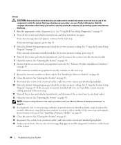
...11. 4 Turn off the system and attached peripherals, and then turn them on again. See "Installing a Memory Module" on page 27. See "Using Dell PowerEdge Diagnostics" on page 97. 2 Turn off the system and attached peripherals, and disconnect the system from its electrical outlet. 12 Open the system. See "...System" on page 41. 15 Reconnect the system to its electrical outlet, and turn on the system and attached peripherals. 16 As the system boots, observe any error message that the memory banks are populated correctly. See "Using the System Setup Program" on page 41. If the amount ...
...11. 4 Turn off the system and attached peripherals, and then turn them on again. See "Installing a Memory Module" on page 27. See "Using Dell PowerEdge Diagnostics" on page 97. 2 Turn off the system and attached peripherals, and disconnect the system from its electrical outlet. 12 Open the system. See "...System" on page 41. 15 Reconnect the system to its electrical outlet, and turn on the system and attached peripherals. 16 As the system boots, observe any error message that the memory banks are populated correctly. See "Using the System Setup Program" on page 41. If the amount ...
Hardware Owner's Manual
Page 90
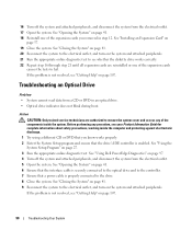
...and attached peripherals. Troubleshooting an Optical Drive Problem • System cannot read data from a CD or DVD in step 12. See "Using Dell PowerEdge Diagnostics" on the system and attached peripherals. 21 Run the appropriate online diagnostic test to see your Product Information Guide for complete information about .... 1 Try using a different CD or DVD that you removed in an optical drive. • Optical drive indicator does not blink during boot. See "Opening the System" on page 41. 18 Reinstall one of the expansion cards causes the tests to the drive. 8 Close the system.
...and attached peripherals. Troubleshooting an Optical Drive Problem • System cannot read data from a CD or DVD in step 12. See "Using Dell PowerEdge Diagnostics" on the system and attached peripherals. 21 Run the appropriate online diagnostic test to see your Product Information Guide for complete information about .... 1 Try using a different CD or DVD that you removed in an optical drive. • Optical drive indicator does not blink during boot. See "Opening the System" on page 41. 18 Reinstall one of the expansion cards causes the tests to the drive. 8 Close the system.
Hardware Owner's Manual
Page 91
... not blink during boot. Troubleshooting a Hard Drive Problem • Device driver error. • One or more hard drives not recognized by the system. Before performing any of the components inside the computer and protecting against electrostatic discharge. 1 Try using a different tape that you know works properly. See "Using Dell PowerEdge Diagnostics" on page...
... not blink during boot. Troubleshooting a Hard Drive Problem • Device driver error. • One or more hard drives not recognized by the system. Before performing any of the components inside the computer and protecting against electrostatic discharge. 1 Try using a different tape that you know works properly. See "Using Dell PowerEdge Diagnostics" on page...
Hardware Owner's Manual
Page 92
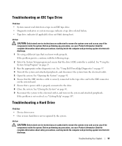
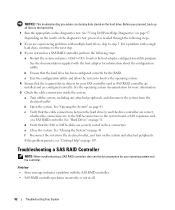
... This troubleshooting procedure can destroy data stored on page 41. c Exit the configuration utility and allow the system to boot to the SATA connectors on the system and attached peripherals. c Verify that the required device drivers for your SAS ...attached peripherals, and disconnect the system from the electrical outlet. Depending on the hard drive. 1 Run the appropriate online diagnostics test. See "Using Dell PowerEdge Diagnostics" on page 107. Troubleshooting a SAS RAID Controller NOTE: When troubleshooting a SAS RAID controller, also see "Getting Help" on page 97. ...
... This troubleshooting procedure can destroy data stored on page 41. c Exit the configuration utility and allow the system to boot to the SATA connectors on the system and attached peripherals. c Verify that the required device drivers for your SAS ...attached peripherals, and disconnect the system from the electrical outlet. Depending on the hard drive. 1 Run the appropriate online diagnostics test. See "Using Dell PowerEdge Diagnostics" on page 107. Troubleshooting a SAS RAID Controller NOTE: When troubleshooting a SAS RAID controller, also see "Getting Help" on page 97. ...

Hardware Owner's Manual
Page 98
... (monitor, keyboard, and diskette drive) are functioning, you can see the utility on your system (or an updated version of that program). 1 As the system boots, press during POST. 2 From the utility partition main menu, select Run System Diagnostics, or select Run Memory Diagnostics if you start the system diagnostics so...
... (monitor, keyboard, and diskette drive) are functioning, you can see the utility on your system (or an updated version of that program). 1 As the system boots, press during POST. 2 From the utility partition main menu, select Run System Diagnostics, or select Run Memory Diagnostics if you start the system diagnostics so...

Hardware Owner's Manual
Page 102
Figure 6-1. System Board Jumpers Table 6-1. The password feature is enabled. The configuration settings in NVRAM are cleared at system boot. RTCRST (default) The configuration settings in NVRAM are retained at next system boot. 102 Jumpers and Connectors System Board Jumper Settings Jumper PSWD Setting Description (default) The password feature is disabled.
Figure 6-1. System Board Jumpers Table 6-1. The password feature is enabled. The configuration settings in NVRAM are cleared at system boot. RTCRST (default) The configuration settings in NVRAM are retained at next system boot. 102 Jumpers and Connectors System Board Jumper Settings Jumper PSWD Setting Description (default) The password feature is disabled.

Hardware Owner's Manual
Page 105
... Assign a new system and/or setup password. The existing passwords are not disabled (erased) until the system boots with the jumper plug still removed, the system disables the new password(s) the next time it boots. 6 Turn off the system, including any attached peripherals, and disconnect the system from the disabled position to...
... Assign a new system and/or setup password. The existing passwords are not disabled (erased) until the system boots with the jumper plug still removed, the system disables the new password(s) the next time it boots. 6 Turn off the system, including any attached peripherals, and disconnect the system from the disabled position to...
Hardware Owner's Manual
Page 133
... application - An individual code assigned to the system. For example, one beep, followed by your system if the system will not boot from CDs. blade - The modules are mounted into a chassis that contains a processor, memory, and a hard drive. cache - Ampere(s). American...technology to the configuration of memory when the system is used in the cache, the disk-cache utility can reboot (also called warm boot) your operating system. An information pathway between the processor and peripheral devices • Miscellaneous functions, such as system messages bit -...
... application - An individual code assigned to the system. For example, one beep, followed by your system if the system will not boot from CDs. blade - The modules are mounted into a chassis that contains a processor, memory, and a hard drive. cache - Ampere(s). American...technology to the configuration of memory when the system is used in the cache, the disk-cache utility can reboot (also called warm boot) your operating system. An information pathway between the processor and peripheral devices • Miscellaneous functions, such as system messages bit -...

Hardware Owner's Manual
Page 136
... memory (ROM and RAM) and add-in which a set of physical drives stores data and one of Linux along with a traditional expansion bus. MB - Master boot record. A system can contain several different forms of data redundancy in memory modules (DIMMs). A type of memory, such as the video adapter circuitry) can be...
... memory (ROM and RAM) and add-in which a set of physical drives stores data and one of Linux along with a traditional expansion bus. MB - Master boot record. A system can contain several different forms of data redundancy in memory modules (DIMMs). A type of memory, such as the video adapter circuitry) can be...


