
Getting Started Guide
Page 8
... to tighten the screws (if any) on the back of the power cables into each connector. Connecting the Keyboard, Mouse, and Monitor Connect the keyboard, mouse, and monitor (optional). Be sure to the system. The connectors on ...the monitor's cable connector. Plug the other end of your system have icons indicating which cable to plug into a grounded electrical outlet or a separate power source such as an uninterrupted power supply (UPS) or a power distribution unit (PDU). 6 Getting Started With Your System
... to tighten the screws (if any) on the back of the power cables into each connector. Connecting the Keyboard, Mouse, and Monitor Connect the keyboard, mouse, and monitor (optional). Be sure to the system. The connectors on ...the monitor's cable connector. Plug the other end of your system have icons indicating which cable to plug into a grounded electrical outlet or a separate power source such as an uninterrupted power supply (UPS) or a power distribution unit (PDU). 6 Getting Started With Your System

Getting Started Guide
Page 9
... that ships with the system. Complete the 0perating System Setup If you purchased a preinstalled operating system, see the Quick Installation Guide. The power indicators should light. Press the power button on the system and monitor (optional). Be sure the operating system is satisfactory. Turning on the System Turn on the system and...
... that ships with the system. Complete the 0perating System Setup If you purchased a preinstalled operating system, see the Quick Installation Guide. The power indicators should light. Press the power button on the system and monitor (optional). Be sure the operating system is satisfactory. Turning on the System Turn on the system and...

Getting Started Guide
Page 11
Drives (continued) Tape drive Flash drive Connectors Back NIC Serial USB Video Front USB Internally accessible IDE channel SATA channels Video Video type Video memory Power AC power supply (per power supply) Wattage Voltage Heat dissipation CMOS Backup Battery Physical Height Width Depth Weight (maximum configuration) one optional internal half-height, 5.25-inch SATA...
Drives (continued) Tape drive Flash drive Connectors Back NIC Serial USB Video Front USB Internally accessible IDE channel SATA channels Video Video type Video memory Power AC power supply (per power supply) Wattage Voltage Heat dissipation CMOS Backup Battery Physical Height Width Depth Weight (maximum configuration) one optional internal half-height, 5.25-inch SATA...
Hardware Owner's Manual
Page 3
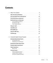
... System Features During Startup 10 Front-Panel Features and Indicators 11 Back-Panel Features and Indicators 13 Connecting External Devices 13 NIC Indicator Codes 14 Power Supply Indicators 15 Diagnostic Lights 15 System Messages 16 Warning Messages 25 Diagnostics Messages 26 Alert Messages 26 2 Using the System Setup Program 27 Entering...
... System Features During Startup 10 Front-Panel Features and Indicators 11 Back-Panel Features and Indicators 13 Connecting External Devices 13 NIC Indicator Codes 14 Power Supply Indicators 15 Diagnostic Lights 15 System Messages 16 Warning Messages 25 Diagnostics Messages 26 Alert Messages 26 2 Using the System Setup Program 27 Entering...
Hardware Owner's Manual
Page 5
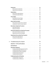
... Cooling Fans 65 Replacing the Cooling Fans 67 System Battery 67 Removing the System Battery 67 Installing the System Battery 68 Power Supply 69 Removing the Power Supply 69 Installing the Power Supply 70 Chassis Intrusion Switch 71 Removing the Chassis Intrusion Switch 71 Installing the Chassis Intrusion Switch 72 Bezel (Service Only...
... Cooling Fans 65 Replacing the Cooling Fans 67 System Battery 67 Removing the System Battery 67 Installing the System Battery 68 Power Supply 69 Removing the Power Supply 69 Installing the Power Supply 70 Chassis Intrusion Switch 71 Removing the Chassis Intrusion Switch 71 Installing the Chassis Intrusion Switch 72 Bezel (Service Only...
Hardware Owner's Manual
Page 6
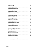
...NIC 83 Troubleshooting a Wet System 84 Troubleshooting a Damaged System 84 Troubleshooting the System Battery 85 Troubleshooting Power Supply 86 Troubleshooting System Cooling Problems 86 Troubleshooting a Fan 87 Troubleshooting System Memory 87 Troubleshooting a ...Troubleshooting a SAS RAID Controller 92 Troubleshooting Expansion Cards 93 Troubleshooting the Microprocessor 95 5 Running the System Diagnostics 97 Using Dell PowerEdge Diagnostics 97 System Diagnostics Features 97 When to Use the System Diagnostics 98 Running the System Diagnostics 98 System Diagnostics Testing...
...NIC 83 Troubleshooting a Wet System 84 Troubleshooting a Damaged System 84 Troubleshooting the System Battery 85 Troubleshooting Power Supply 86 Troubleshooting System Cooling Problems 86 Troubleshooting a Fan 87 Troubleshooting System Memory 87 Troubleshooting a ...Troubleshooting a SAS RAID Controller 92 Troubleshooting Expansion Cards 93 Troubleshooting the Microprocessor 95 5 Running the System Diagnostics 97 Using Dell PowerEdge Diagnostics 97 System Diagnostics Features 97 When to Use the System Diagnostics 98 Running the System Diagnostics 98 System Diagnostics Testing...
Hardware Owner's Manual
Page 12
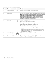
...is faulty. NOTE: If you turn off the system using the power button and the system is running an ACPI-compliant operating system, the power is off , the power supply may need to assist in a low power state. The system is turned off . Steady amber - Front-Panel...USB connectors (2) Description Connects USB 2.0-compliant devices to the system. 6 power button 7 power light 8 network link light The power button controls the DC power supply output to see if the specific problem is off . The system is powering up. • If the hard drive indicator is identified. Blinking green ...
...is faulty. NOTE: If you turn off the system using the power button and the system is running an ACPI-compliant operating system, the power is off , the power supply may need to assist in a low power state. The system is turned off . Steady amber - Front-Panel...USB connectors (2) Description Connects USB 2.0-compliant devices to the system. 6 power button 7 power light 8 network link light The power button controls the DC power supply output to see if the specific problem is off . The system is powering up. • If the hard drive indicator is identified. Blinking green ...

Hardware Owner's Manual
Page 13
About Your System 13 Back-Panel Features and Indicators 1 2 3 4 5 6 7 1 voltage selection switch 4 USB connectors (5) 7 I/O expansion-card slots (5) 2 power connector 5 serial connector 3 NIC connector 6 video connector Connecting External Devices When connecting external devices to your system, follow these guidelines: • Most devices must be ...
About Your System 13 Back-Panel Features and Indicators 1 2 3 4 5 6 7 1 voltage selection switch 4 USB connectors (5) 7 I/O expansion-card slots (5) 2 power connector 5 serial connector 3 NIC connector 6 video connector Connecting External Devices When connecting external devices to your system, follow these guidelines: • Most devices must be ...
Hardware Owner's Manual
Page 15
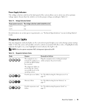
.... Diagnostic Indicator Codes Code Causes Corrective Action The computer is off condition or a outlet and press the power button. See "Troubleshooting System Memory" on system power requirements, see "Technical Specifications" in a Plug the computer into a working electrical normal off . Voltage Selection... Switch If your power source is set to the operating system. Table 1-5. possible pre-BIOS failure has occurred. Possible expansion card See ...
.... Diagnostic Indicator Codes Code Causes Corrective Action The computer is off condition or a outlet and press the power button. See "Troubleshooting System Memory" on system power requirements, see "Technical Specifications" in a Plug the computer into a working electrical normal off . Voltage Selection... Switch If your power source is set to the operating system. Table 1-5. possible pre-BIOS failure has occurred. Possible expansion card See ...

Hardware Owner's Manual
Page 26
... Messages When you run system diagnostics, an error message may result. Diagnostic error messages are not covered in that section for drive, temperature, fan, and power conditions.
... Messages When you run system diagnostics, an error message may result. Diagnostic error messages are not covered in that section for drive, temperature, fan, and power conditions.

Hardware Owner's Manual
Page 33
... to NIC enables the NIC to Off. Pressing any edit key acknowledges the intrusion and arms the system to the last power state the system was turned off when the power is in NICs will be able to wake up the system. Off disables the NIC from the Suspend, Hibernate, or Off... or Off states. Determines the time that you want the system to perform a Remote Wake Up, you want the system to turn on when the power is turned on remotely from waking up the system. NOTE: With this field displays DETECTED when the chassis cover has been opened. On enables the...
... to NIC enables the NIC to Off. Pressing any edit key acknowledges the intrusion and arms the system to the last power state the system was turned off when the power is in NICs will be able to wake up the system. Off disables the NIC from the Suspend, Hibernate, or Off... or Off states. Determines the time that you want the system to perform a Remote Wake Up, you want the system to turn on when the power is turned on remotely from waking up the system. NOTE: With this field displays DETECTED when the chassis cover has been opened. On enables the...

Hardware Owner's Manual
Page 39
...; Optical and tape drives • Hard drives • Expansion cards • SAS controller card • Memory • Microprocessor • Cooling fans • System battery • Power supply • Chassis intrusion switch • Bezel • I/O panel • System board Recommended Tools You may need the following items to perform the procedures in...
...; Optical and tape drives • Hard drives • Expansion cards • SAS controller card • Memory • Microprocessor • Cooling fans • System battery • Power supply • Chassis intrusion switch • Bezel • I/O panel • System board Recommended Tools You may need the following items to perform the procedures in...

Hardware Owner's Manual
Page 40
... 6 card cage fan 9 3.5-inch drive bay The system board can accommodate one processor, five expansion cards, and four memory modules. Power is supplied to two SAS or SATA hard drives. Inside the System In Figure 3-1, the system cover is opened to provide an interior view of ... drive bays provide space for SAS hard drives. A controller expansion card is required for up to the system board and internal peripherals through a single nonredundant power supply. 40 Installing System Components Figure 3-1.
... 6 card cage fan 9 3.5-inch drive bay The system board can accommodate one processor, five expansion cards, and four memory modules. Power is supplied to two SAS or SATA hard drives. Inside the System In Figure 3-1, the system cover is opened to provide an interior view of ... drive bays provide space for SAS hard drives. A controller expansion card is required for up to the system board and internal peripherals through a single nonredundant power supply. 40 Installing System Components Figure 3-1.

Hardware Owner's Manual
Page 41
... inside the computer and protecting against electrostatic discharge. 1 Turn off the system and attached peripherals, and disconnect the system from the electrical outlet. 2 Press the power button to ground the system board. 3 If you open and close the cover, the chassis intrusion detector, if enabled, causes the following message to appear...
... inside the computer and protecting against electrostatic discharge. 1 Turn off the system and attached peripherals, and disconnect the system from the electrical outlet. 2 Press the power button to ground the system board. 3 If you open and close the cover, the chassis intrusion detector, if enabled, causes the following message to appear...
Hardware Owner's Manual
Page 44
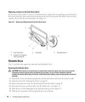
... into place. From the back of the bezel, fit the tab on the end of the insert into the notch on page 42. 4 Disconnect the power and data cables from the electrical outlet. 2 Open the system. Replacing an Insert on the Front Drive Bezel If you remove a drive in the 3.5-inch...
... into place. From the back of the bezel, fit the tab on the end of the insert into the notch on page 42. 4 Disconnect the power and data cables from the electrical outlet. 2 Open the system. Replacing an Insert on the Front Drive Bezel If you remove a drive in the 3.5-inch...

Hardware Owner's Manual
Page 45
Removing or Installing a Diskette Drive 4 3 5 2 1 6 1 arrow on the sliding plate 4 power cable to diskette drive (P7) 2 sliding plate 5 data cable to diskette drive 3 drive-stop tab 6 data cable to system board connector (FLOPPY) 7 If you are ...
Removing or Installing a Diskette Drive 4 3 5 2 1 6 1 arrow on the sliding plate 4 power cable to diskette drive (P7) 2 sliding plate 5 data cable to diskette drive 3 drive-stop tab 6 data cable to system board connector (FLOPPY) 7 If you are ...

Hardware Owner's Manual
Page 46
... Figure 3-4; See Figure 3-5 and Figure 6-2. 13 Replace the front drive bezel. See Figure 3-5. NOTE: Inserting a diskette drive into the sliding plate. 11 Connect the P7 power cable to the diskette drive as shown in the proper position. See "Closing the System" on page 41. 15 Reconnect the system to the electrical...
... Figure 3-4; See Figure 3-5 and Figure 6-2. 13 Replace the front drive bezel. See Figure 3-5. NOTE: Inserting a diskette drive into the sliding plate. 11 Connect the P7 power cable to the diskette drive as shown in the proper position. See "Closing the System" on page 41. 15 Reconnect the system to the electrical...
Hardware Owner's Manual
Page 47
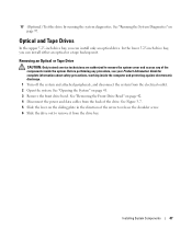
... optical or a tape backup unit. 17 (Optional) Test the drive by running the system diagnostics. See Figure 3-7. 5 Slide the lever on page 42. 4 Disconnect the power and data cables from the drive bay. See "Opening the System" on page 97. Removing an Optical or Tape Drive CAUTION: Only trained service technicians...
... optical or a tape backup unit. 17 (Optional) Test the drive by running the system diagnostics. See Figure 3-7. 5 Slide the lever on page 42. 4 Disconnect the power and data cables from the drive bay. See "Opening the System" on page 97. Removing an Optical or Tape Drive CAUTION: Only trained service technicians...

Hardware Owner's Manual
Page 48
.... 9 Replace the front drive bezel. Removing and Installing an Optical or Tape Drive 2 3 1 4 1 sliding plate 4 IDE connector on system board 2 IDE data cable to drive 3 power cable to the electrical outlet, and turn on front drive bezel. See "Closing the System" on page 41. 11 Reconnect the system to drive 7 If...
.... 9 Replace the front drive bezel. Removing and Installing an Optical or Tape Drive 2 3 1 4 1 sliding plate 4 IDE connector on system board 2 IDE data cable to drive 3 power cable to the electrical outlet, and turn on front drive bezel. See "Closing the System" on page 41. 11 Reconnect the system to drive 7 If...

Hardware Owner's Manual
Page 50
... turn on the system board. See Figure 3-7. 10 Attach the data cable: • If you hear a click or feel the drive securely installed. 9 Attach the power cable to allow for airflow between the fan and cooling vents. 12 Replace the front drive bezel.
... turn on the system board. See Figure 3-7. 10 Attach the data cable: • If you hear a click or feel the drive securely installed. 9 Attach the power cable to allow for airflow between the fan and cooling vents. 12 Replace the front drive bezel.


