Getting Started Guide
Page 5
...; Dual-channel IDE controller that supports up to two cabled SATA hard drives. • Two 32-bit, 33-MHz I/O expansion card slots, one x1 lane-width PCIe expansion slot, one x8 lane-width PCIe expansion slot. • An integrated VGA-compatible video subsystem with an integrated SATA controller or - All processors are supported in the four memory module sockets on the system board; NOTE: Use the System Setup program to two internal 3.5-inch Serial-Attached SCSI (SAS) hard drives with a SAS controller card • One...
...; Dual-channel IDE controller that supports up to two cabled SATA hard drives. • Two 32-bit, 33-MHz I/O expansion card slots, one x1 lane-width PCIe expansion slot, one x8 lane-width PCIe expansion slot. • An integrated VGA-compatible video subsystem with an integrated SATA controller or - All processors are supported in the four memory module sockets on the system board; NOTE: Use the System Setup program to two internal 3.5-inch Serial-Attached SCSI (SAS) hard drives with a SAS controller card • One...
Hardware Owner's Manual
Page 5
... I/O Panel Assembly 75 Replacing the I/O Panel Assembly 76 System Board (Service Only Parts Procedure 76 Removing the System Board 76 Installing the System Board 78 4 Troubleshooting Your System 79 Safety First-For You and Your System 79 Start-Up Routine 79 Checking the Equipment 79 Troubleshooting IRQ Assignment Conflicts 80 Troubleshooting External Connections 80 Troubleshooting the Video Subsystem 81 Troubleshooting the Keyboard 81 Troubleshooting the Mouse 81 Troubleshooting Basic I/O Problems 82 Troubleshooting a Serial Port 82 Troubleshooting a USB Device...
... I/O Panel Assembly 75 Replacing the I/O Panel Assembly 76 System Board (Service Only Parts Procedure 76 Removing the System Board 76 Installing the System Board 78 4 Troubleshooting Your System 79 Safety First-For You and Your System 79 Start-Up Routine 79 Checking the Equipment 79 Troubleshooting IRQ Assignment Conflicts 80 Troubleshooting External Connections 80 Troubleshooting the Video Subsystem 81 Troubleshooting the Keyboard 81 Troubleshooting the Mouse 81 Troubleshooting Basic I/O Problems 82 Troubleshooting a Serial Port 82 Troubleshooting a USB Device...
Hardware Owner's Manual
Page 16
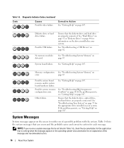
... Help" on page 82. If the problem persists, see "Getting Help" on page 107. See "Troubleshooting a USB Device" on page 107. System Messages System messages appear on error. Memory configuration See "Troubleshooting System Memory" on the screen to notify you receive a system message that the diskette drive and hard drive are properly connected. Diskette drive or hard drive failure. Ensure that is running when the message appears or the operating system's documentation for each...
... Help" on page 82. If the problem persists, see "Getting Help" on page 107. See "Troubleshooting a USB Device" on page 107. System Messages System messages appear on error. Memory configuration See "Troubleshooting System Memory" on the screen to notify you receive a system message that the diskette drive and hard drive are properly connected. Diskette drive or hard drive failure. Ensure that is running when the message appears or the operating system's documentation for each...
Hardware Owner's Manual
Page 31
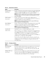
...: PXE or RPL is set the serial port to boot from a USB device. Enables or disables the front USB ports independently of some applications will have one or two logical processors. Table 2-4. Onboard Devices Options Option Integrated NIC (On default) USB Controller (On default) Front USB Ports (On default) Serial Port #1 (Auto default) Description Enables or disables the integrated Network Interface Controller (NIC). No Boot enables the controller, but disables the ability to Auto and add an expansion card with additional logical processors installed. Off disables the...
...: PXE or RPL is set the serial port to boot from a USB device. Enables or disables the front USB ports independently of some applications will have one or two logical processors. Table 2-4. Onboard Devices Options Option Integrated NIC (On default) USB Controller (On default) Front USB Ports (On default) Serial Port #1 (Auto default) Description Enables or disables the integrated Network Interface Controller (NIC). No Boot enables the controller, but disables the ability to Auto and add an expansion card with additional logical processors installed. Off disables the...
Hardware Owner's Manual
Page 34
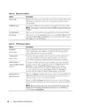
... default) Numlock Key (On default) POST Hotkeys (Setup and Boot Menu default) Keyboard Errors (Report default) Description When enabled, this feature is detected during POST, the BIOS will display the error message and continue booting the system. Off does not skip any steps during POST, the BIOS will display the error message and prompt you to restore all the entries. Setup displays the setup message only (F2=Setup). Clear Log clears the Event Log. On commands the right keypad keys to function as numbers. If the service...
... default) Numlock Key (On default) POST Hotkeys (Setup and Boot Menu default) Keyboard Errors (Report default) Description When enabled, this feature is detected during POST, the BIOS will display the error message and continue booting the system. Off does not skip any steps during POST, the BIOS will display the error message and prompt you to restore all the entries. Setup displays the setup message only (F2=Setup). Clear Log clears the Event Log. On commands the right keypad keys to function as numbers. If the service...
Hardware Owner's Manual
Page 35
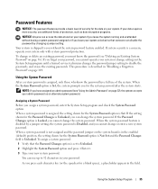
... can access the data stored on the system board is in the enabled (default) position, the setting shown for a blank space), a placeholder appears in the System Setup program until a trained service technician changes the password jumper setting to you without having a system password assigned or if you for the System Password option is Locked, you assign a system password, enter the System Setup program and check the System Password...
... can access the data stored on the system board is in the enabled (default) position, the setting shown for a blank space), a placeholder appears in the System Setup program until a trained service technician changes the password jumper setting to you without having a system password assigned or if you for the System Password option is Locked, you assign a system password, enter the System Setup program and check the System Password...
Hardware Owner's Manual
Page 36
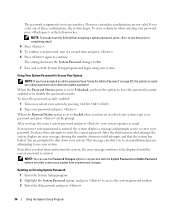
... error message continues to be displayed until the correct password is entered, the system displays a message and prompts you turn on page 37), the system accepts your password, type it a second time and press . 6 Press again to access the system password window. 3 Enter the old password, and press . 36 Using the System Setup Program To erase a character when entering your system operates as an alternate system password...
... error message continues to be displayed until the correct password is entered, the system displays a message and prompts you turn on page 37), the system accepts your password, type it a second time and press . 6 Press again to access the system password window. 3 Enter the old password, and press . 36 Using the System Setup Program To erase a character when entering your system operates as an alternate system password...
Hardware Owner's Manual
Page 38
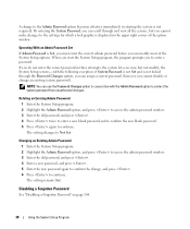
... following exception: if System Password is not Set and is displayed in conjunction with the Admin Password option to protect the system password from unauthorized changes. Operating With an Admin Password Set If Admin Password is not required). Deleting an Existing Admin Password 1 Enter the System Setup program. 2 Highlight the Admin Password option, and press to access the admin password window. 3 Enter the old password, and press . 4 Press...
... following exception: if System Password is not Set and is displayed in conjunction with the Admin Password option to protect the system password from unauthorized changes. Operating With an Admin Password Set If Admin Password is not required). Deleting an Existing Admin Password 1 Enter the System Setup program. 2 Highlight the Admin Password option, and press to access the admin password window. 3 Enter the old password, and press . 4 Press...
Hardware Owner's Manual
Page 82
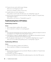
... Setup program and ensure that the USB port is not operating properly. Troubleshooting a USB Device Problem • System message indicates a problem with a USB device. • Device connected to a USB port is enabled. If the mouse is not damaged, go to a particular application, see "Getting Help" on page 27. 2 If the problem is not resolved, see the application documentation for specific port configuration requirements that the USB ports are enabled. If the problem is confined to step 4. See "Using Dell PowerEdge Diagnostics...
... Setup program and ensure that the USB port is not operating properly. Troubleshooting a USB Device Problem • System message indicates a problem with a USB device. • Device connected to a USB port is enabled. If the mouse is not damaged, go to a particular application, see "Getting Help" on page 27. 2 If the problem is not resolved, see the application documentation for specific port configuration requirements that the USB ports are enabled. If the problem is confined to step 4. See "Using Dell PowerEdge Diagnostics...
Hardware Owner's Manual
Page 83
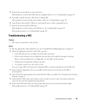
... the switch or hub. Action 1 Run the appropriate online diagnostic test. Remove and reinstall the drivers if applicable. See "Using the System Setup Program" on page 107. 6 Turn off the system and the USB device, and swap the device with network. If the problem is resolved, replace the USB device. See "Using Dell PowerEdge Diagnostics" on page 97. 2 Check the appropriate indicator on the network are of an integrated NIC, see the documentation for the NIC card...
... the switch or hub. Action 1 Run the appropriate online diagnostic test. Remove and reinstall the drivers if applicable. See "Using the System Setup Program" on page 107. 6 Turn off the system and the USB device, and swap the device with network. If the problem is resolved, replace the USB device. See "Using Dell PowerEdge Diagnostics" on page 97. 2 Check the appropriate indicator on the network are of an integrated NIC, see the documentation for the NIC card...
Hardware Owner's Manual
Page 87
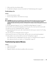
... Memory Problem • Faulty memory module. • Faulty system board. • Diagnostic indicator code indicates a problem with system memory. See "Using Dell PowerEdge Diagnostics" on page 41. 4 Ensure that the faulty fan's power cable is firmly attached to remove the system cover and access any procedure, see "Getting Help" on the system and attached peripherals. 7 If the problem is removed or has failed. Action CAUTION: Only trained service technicians are authorized to the fan power connector...
... Memory Problem • Faulty memory module. • Faulty system board. • Diagnostic indicator code indicates a problem with system memory. See "Using Dell PowerEdge Diagnostics" on page 41. 4 Ensure that the faulty fan's power cable is firmly attached to remove the system cover and access any procedure, see "Getting Help" on the system and attached peripherals. 7 If the problem is removed or has failed. Action CAUTION: Only trained service technicians are authorized to the fan power connector...
Hardware Owner's Manual
Page 89
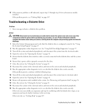
... the System Setup program and verify that a power cable is configured correctly. Continue to see "Getting Help" on page 107. Troubleshooting Your System 89 Troubleshooting a Diskette Drive Problem • Error message indicates a diskette drive problem. See "Opening the System" on the system and attached peripherals. 9 Run the appropriate online diagnostic test to remove the system cover and access any procedure, see your Product Information Guide for each memory module installed. See "Removing an Expansion Card" on...
... the System Setup program and verify that a power cable is configured correctly. Continue to see "Getting Help" on page 107. Troubleshooting Your System 89 Troubleshooting a Diskette Drive Problem • Error message indicates a diskette drive problem. See "Opening the System" on the system and attached peripherals. 9 Run the appropriate online diagnostic test to remove the system cover and access any procedure, see your Product Information Guide for each memory module installed. See "Removing an Expansion Card" on...
Hardware Owner's Manual
Page 92
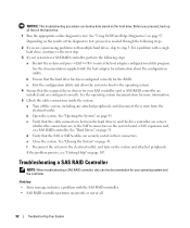
... "Using Dell PowerEdge Diagnostics" on page 41. If the problem persists, see the documentation for your system has a SAS RAID controller, perform the following steps. 2 If you proceed, back up all . 92 Troubleshooting Your System d Verify that the cable connections between the hard drive(s) and the drive controller are correct, whether the connections are securely seated in their connectors. See the operating system documentation for the RAID. b Ensure that the required device drivers for...
... "Using Dell PowerEdge Diagnostics" on page 41. If the problem persists, see the documentation for your system has a SAS RAID controller, perform the following steps. 2 If you proceed, back up all . 92 Troubleshooting Your System d Verify that the cable connections between the hard drive(s) and the drive controller are correct, whether the connections are securely seated in their connectors. See the operating system documentation for the RAID. b Ensure that the required device drivers for...
Hardware Owner's Manual
Page 93
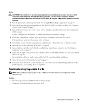
... that the cables are firmly connected to remove the system cover and access any necessary corrections, and restart the system. Problem • Error message indicates a problem with an expansion card. • Expansion card performs incorrectly or not at all. Troubleshooting Your System 93 See "Using Dell PowerEdge Diagnostics" on page 107. See "Opening the System" on page 51. Action CAUTION: Only trained service technicians are correct. Ensure that the SAS RAID controller is...
... that the cables are firmly connected to remove the system cover and access any necessary corrections, and restart the system. Problem • Error message indicates a problem with an expansion card. • Expansion card performs incorrectly or not at all. Troubleshooting Your System 93 See "Using Dell PowerEdge Diagnostics" on page 107. See "Opening the System" on page 51. Action CAUTION: Only trained service technicians are correct. Ensure that the SAS RAID controller is...
Hardware Owner's Manual
Page 133
.... A module that includes power supplies and fans. Baseboard management controller. Your system contains an expansion bus that is in the form of a pattern of data or instructions for the peripheral devices connected to communicate with controllers for quick data retrieval. ambient temperature - American National Standards Institute. Software designed to direct configuration and power management. The modules are mounted into a chassis that contains a processor, memory, and a hard drive. Otherwise, you start your system if the system will not boot...
.... A module that includes power supplies and fans. Baseboard management controller. Your system contains an expansion bus that is in the form of a pattern of data or instructions for the peripheral devices connected to communicate with controllers for quick data retrieval. ambient temperature - American National Standards Institute. Software designed to direct configuration and power management. The modules are mounted into a chassis that contains a processor, memory, and a hard drive. Otherwise, you start your system if the system will not boot...
Hardware Owner's Manual
Page 134
... off them. DMA - Error checking and correction. EMC - EMI - ERA allows you start the program for your network server using a remote access controller. Your system contains an expansion bus that relieves the system's processor of -band," server management on a disk in card, such as relevant to running in memory modules that plugs into IP addresses, such as the power button and power indicator. expansion card - cm - cmos - controller - Central processing unit. Some device drivers-such as network drivers-must load when...
... off them. DMA - Error checking and correction. EMC - EMI - ERA allows you start the program for your network server using a remote access controller. Your system contains an expansion bus that relieves the system's processor of -band," server management on a disk in card, such as relevant to running in memory modules that plugs into IP addresses, such as the power button and power indicator. expansion card - cm - cmos - controller - Central processing unit. Some device drivers-such as network drivers-must load when...

Hardware Owner's Manual
Page 138
... connected in the cable. Transmission Control Protocol/Internet Protocol. A standard interface that has two or more disks in the configuration software for video adapters with faster data transmission rates than previous standards. Synchronous dynamic random-access memory. Second(s). System Setup program - Used to describe a system that allows a network manager to I /O bus interface with greater resolution and color display capabilities than standard ports. SAS - The amount of space used most of your system's hardware...
... connected in the cable. Transmission Control Protocol/Internet Protocol. A standard interface that has two or more disks in the configuration software for video adapters with faster data transmission rates than previous standards. Synchronous dynamic random-access memory. Second(s). System Setup program - Used to describe a system that allows a network manager to I /O bus interface with greater resolution and color display capabilities than standard ports. SAS - The amount of space used most of your system's hardware...
Hardware Owner's Manual
Page 139
.... USB devices can display (with the monitor) your system's RAM. utility - VDC - Video graphics array. video adapter - video driver - Video drivers may be communicated between otherwise unconnected sources. video resolution - Watt(s). A start Windows, it consults the win.ini file to Linux, is an operating system written in the C programming language. Windows 2000 - A set of Microsoft software technologies that enable software integration through the use of colors that automatically supplies power to other hubs or switches without requiring a crossover cable...
.... USB devices can display (with the monitor) your system's RAM. utility - VDC - Video graphics array. video adapter - video driver - Video drivers may be communicated between otherwise unconnected sources. video resolution - Watt(s). A start Windows, it consults the win.ini file to Linux, is an operating system written in the C programming language. Windows 2000 - A set of Microsoft software technologies that enable software integration through the use of colors that automatically supplies power to other hubs or switches without requiring a crossover cable...
Hardware Owner's Manual
Page 142
.../DVD drive, 49 chassis intrusion switch, 72 cooling fans, 67 diskette drive, 45 expansion cards, 57 hard drive, 52 I/O panel, 76 installing (continued) memory, 60 power supply, 70 processor, 65 system battery, 67 system board, 78 tape drive, 49 IRQs avoiding conflicts, 80 line assignments, 80 J jumpers, 101 K keyboard troubleshooting, 81 M memory 4-GB configurations, 59 branches, 58 channels, 58 installing, 60 removing, 60 replacing, 60 troubleshooting, 87 upgrade kits, 59 messages alert, 26 error messages, 27 system, 16 warning, 25 microprocessor removing, 62 replacing, 65 troubleshooting...
.../DVD drive, 49 chassis intrusion switch, 72 cooling fans, 67 diskette drive, 45 expansion cards, 57 hard drive, 52 I/O panel, 76 installing (continued) memory, 60 power supply, 70 processor, 65 system battery, 67 system board, 78 tape drive, 49 IRQs avoiding conflicts, 80 line assignments, 80 J jumpers, 101 K keyboard troubleshooting, 81 M memory 4-GB configurations, 59 branches, 58 channels, 58 installing, 60 removing, 60 replacing, 60 troubleshooting, 87 upgrade kits, 59 messages alert, 26 error messages, 27 system, 16 warning, 25 microprocessor removing, 62 replacing, 65 troubleshooting...
Hardware Owner's Manual
Page 143
... switch, 72 cooling fans, 67 diskette drive, 45 expansion cards, 57 front drive bezel, 43 I/O panel, 76 memory, 60 replacing (continued) power supply, 70 processor, 65 system board, 78 S safety, 79 SAS controller card installing, 58 troubleshooting, 92 SAS hard drive. See hard drive. SATA hard drive. securing your system, 36 serial port connector, 13 troubleshooting, 82 setup password features, 35 startup accessing system features, 10 status messages systems management, 16 support contacting Dell, 112 system closing, 41 opening, 41 system battery removing, 67 system board connectors...
... switch, 72 cooling fans, 67 diskette drive, 45 expansion cards, 57 front drive bezel, 43 I/O panel, 76 memory, 60 replacing (continued) power supply, 70 processor, 65 system board, 78 S safety, 79 SAS controller card installing, 58 troubleshooting, 92 SAS hard drive. See hard drive. SATA hard drive. securing your system, 36 serial port connector, 13 troubleshooting, 82 setup password features, 35 startup accessing system features, 10 status messages systems management, 16 support contacting Dell, 112 system closing, 41 opening, 41 system battery removing, 67 system board connectors...


