
Getting Started Guide
Page 8
... which cable to plug into a grounded electrical outlet or a separate power source such as an uninterrupted power supply (UPS) or a power distribution unit (PDU). 6 Getting Started With Your System Connecting the Power Connect the monitor power cable to the monitor (optional), and connect the system's power cable to tighten the screws (if any) on the back of...
... which cable to plug into a grounded electrical outlet or a separate power source such as an uninterrupted power supply (UPS) or a power distribution unit (PDU). 6 Getting Started With Your System Connecting the Power Connect the monitor power cable to the monitor (optional), and connect the system's power cable to tighten the screws (if any) on the back of...

Getting Started Guide
Page 11
Drives (continued) Tape drive Flash drive Connectors Back NIC Serial USB Video Front USB Internally accessible IDE channel SATA channels Video Video type Video memory Power AC power supply (per power supply) Wattage Voltage Heat dissipation CMOS Backup Battery Physical Height Width Depth Weight (maximum configuration) one optional internal half-height, 5.25-inch SATA (for use...
Drives (continued) Tape drive Flash drive Connectors Back NIC Serial USB Video Front USB Internally accessible IDE channel SATA channels Video Video type Video memory Power AC power supply (per power supply) Wattage Voltage Heat dissipation CMOS Backup Battery Physical Height Width Depth Weight (maximum configuration) one optional internal half-height, 5.25-inch SATA (for use...
Hardware Owner's Manual
Page 3
... System Features During Startup 10 Front-Panel Features and Indicators 11 Back-Panel Features and Indicators 13 Connecting External Devices 13 NIC Indicator Codes 14 Power Supply Indicators 15 Diagnostic Lights 15 System Messages 16 Warning Messages 25 Diagnostics Messages 26 Alert Messages 26 2 Using the System Setup Program 27 Entering the...
... System Features During Startup 10 Front-Panel Features and Indicators 11 Back-Panel Features and Indicators 13 Connecting External Devices 13 NIC Indicator Codes 14 Power Supply Indicators 15 Diagnostic Lights 15 System Messages 16 Warning Messages 25 Diagnostics Messages 26 Alert Messages 26 2 Using the System Setup Program 27 Entering the...
Hardware Owner's Manual
Page 5
... the Cooling Fans 65 Replacing the Cooling Fans 67 System Battery 67 Removing the System Battery 67 Installing the System Battery 68 Power Supply 69 Removing the Power Supply 69 Installing the Power Supply 70 Chassis Intrusion Switch 71 Removing the Chassis Intrusion Switch 71 Installing the Chassis Intrusion Switch 72 Bezel (Service Only Parts Procedure...
... the Cooling Fans 65 Replacing the Cooling Fans 67 System Battery 67 Removing the System Battery 67 Installing the System Battery 68 Power Supply 69 Removing the Power Supply 69 Installing the Power Supply 70 Chassis Intrusion Switch 71 Removing the Chassis Intrusion Switch 71 Installing the Chassis Intrusion Switch 72 Bezel (Service Only Parts Procedure...
Hardware Owner's Manual
Page 6
...NIC 83 Troubleshooting a Wet System 84 Troubleshooting a Damaged System 84 Troubleshooting the System Battery 85 Troubleshooting Power Supply 86 Troubleshooting System Cooling Problems 86 Troubleshooting a Fan 87 Troubleshooting System Memory 87 Troubleshooting a Diskette ...Troubleshooting a SAS RAID Controller 92 Troubleshooting Expansion Cards 93 Troubleshooting the Microprocessor 95 5 Running the System Diagnostics 97 Using Dell PowerEdge Diagnostics 97 System Diagnostics Features 97 When to Use the System Diagnostics 98 Running the System Diagnostics 98 System Diagnostics ...
...NIC 83 Troubleshooting a Wet System 84 Troubleshooting a Damaged System 84 Troubleshooting the System Battery 85 Troubleshooting Power Supply 86 Troubleshooting System Cooling Problems 86 Troubleshooting a Fan 87 Troubleshooting System Memory 87 Troubleshooting a Diskette ...Troubleshooting a SAS RAID Controller 92 Troubleshooting Expansion Cards 93 Troubleshooting the Microprocessor 95 5 Running the System Diagnostics 97 Using Dell PowerEdge Diagnostics 97 System Diagnostics Features 97 When to Use the System Diagnostics 98 Running the System Diagnostics 98 System Diagnostics ...
Hardware Owner's Manual
Page 12
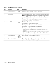
... green - Steady amber - Front-Panel Components (continued) Item Component Icon 5 USB connectors (2) Description Connects USB 2.0-compliant devices to the system. 6 power button 7 power light 8 network link light The power button controls the DC power supply output to be replaced. • If the hard drive indicator is off . See "Diagnostic Lights" on . Steady green - The system...
... green - Steady amber - Front-Panel Components (continued) Item Component Icon 5 USB connectors (2) Description Connects USB 2.0-compliant devices to the system. 6 power button 7 power light 8 network link light The power button controls the DC power supply output to be replaced. • If the hard drive indicator is off . See "Diagnostic Lights" on . Steady green - The system...
Hardware Owner's Manual
Page 15
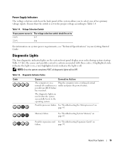
...front panel display error codes during system startup. Table 1-4. A highlighted circle indicates the light is in your power source is off condition or a outlet and press the power button. Diagnostic Indicator Codes Code Causes Corrective Action The computer is on; See "Troubleshooting the Microprocessor" on ... Guide. Possible processor failure. Table 1-5. Memory failure. page 93. Ensure that the switch is set to Table 1-4. Power Supply Indicators The voltage selection switch on the back panel of two primary voltage inputs. See "Troubleshooting System Memory" on page 95.
...front panel display error codes during system startup. Table 1-4. A highlighted circle indicates the light is in your power source is off condition or a outlet and press the power button. Diagnostic Indicator Codes Code Causes Corrective Action The computer is on; See "Troubleshooting the Microprocessor" on ... Guide. Possible processor failure. Table 1-5. Memory failure. page 93. Ensure that the switch is set to Table 1-4. Power Supply Indicators The voltage selection switch on the back panel of two primary voltage inputs. See "Troubleshooting System Memory" on page 95.

Hardware Owner's Manual
Page 39
...; Optical and tape drives • Hard drives • Expansion cards • SAS controller card • Memory • Microprocessor • Cooling fans • System battery • Power supply • Chassis intrusion switch • Bezel • I/O panel • System board Recommended Tools You may need the following items to perform the procedures in this...
...; Optical and tape drives • Hard drives • Expansion cards • SAS controller card • Memory • Microprocessor • Cooling fans • System battery • Power supply • Chassis intrusion switch • Bezel • I/O panel • System board Recommended Tools You may need the following items to perform the procedures in this...

Hardware Owner's Manual
Page 40
... and shroud assembly 8 drive cage hard drives (2) processor cooling fan 3 power supply 6 card cage fan 9 3.5-inch drive bay The system board can accommodate one processor, five expansion cards, and four memory modules. Power is required for up to the system board and internal peripherals through a... single nonredundant power supply. 40 Installing System Components Figure 3-1. Drive bays in the front of the system...
... and shroud assembly 8 drive cage hard drives (2) processor cooling fan 3 power supply 6 card cage fan 9 3.5-inch drive bay The system board can accommodate one processor, five expansion cards, and four memory modules. Power is required for up to the system board and internal peripherals through a... single nonredundant power supply. 40 Installing System Components Figure 3-1. Drive bays in the front of the system...

Hardware Owner's Manual
Page 69
... the System" on page 41. 3 Depending on the side of the power supply. 7 Using a #2 Phillips screwdriver, remove the four Phillips screws that secure the power supply to the back panel. 8 Press the power-supply release tab down and slide the power supply toward the front of the system, then lift it out of the components... these cables properly when you release the tabs and remove the cables from the fan housing and lift it aside to attach to the new power supply. See Figure 3-19. 9 Remove the cable clamp and set it out. 6 Remove the IDE, I/O panel, and SATA cables (if present) attached...
... the System" on page 41. 3 Depending on the side of the power supply. 7 Using a #2 Phillips screwdriver, remove the four Phillips screws that secure the power supply to the back panel. 8 Press the power-supply release tab down and slide the power supply toward the front of the system, then lift it out of the components... these cables properly when you release the tabs and remove the cables from the fan housing and lift it aside to attach to the new power supply. See Figure 3-19. 9 Remove the cable clamp and set it out. 6 Remove the IDE, I/O panel, and SATA cables (if present) attached...

Hardware Owner's Manual
Page 70
Figure 3-19. Removing the Power Supply 2 1 3 4 1 power supply release tab 4 cable clamp 2 power supply 3 screws (4) Installing the Power Supply 1 Attach the cable clamp to the new power supply. 2 Align the power supply mounting holes with the mounting holes on the back panel. 3 Slide the power supply toward the back panel until it snaps into place over the power-supply release tab. 4 Using a #2 Phillips screwdriver, install the four...
Figure 3-19. Removing the Power Supply 2 1 3 4 1 power supply release tab 4 cable clamp 2 power supply 3 screws (4) Installing the Power Supply 1 Attach the cable clamp to the new power supply. 2 Align the power supply mounting holes with the mounting holes on the back panel. 3 Slide the power supply toward the back panel until it snaps into place over the power-supply release tab. 4 Using a #2 Phillips screwdriver, install the four...

Hardware Owner's Manual
Page 76
... computer and protecting against electrostatic discharge. 1 Fit the I/O panel assembly into the holding tab on your Product Information Guide for connector locations. • Two power-supply cables from the POWER and 12VPOWER connectors • Diskette data cable from the FLOPPY connector • I/O panel cable from the FRONTPANEL connector • 5.25-inch device data...
... computer and protecting against electrostatic discharge. 1 Fit the I/O panel assembly into the holding tab on your Product Information Guide for connector locations. • Two power-supply cables from the POWER and 12VPOWER connectors • Diskette data cable from the FLOPPY connector • I/O panel cable from the FRONTPANEL connector • 5.25-inch device data...
Hardware Owner's Manual
Page 78
... Components See Figure 3-23. See "Replacing the Processor" on page 60. 6 Install the expansion cards and connect any cables. See Figure 6-2. • Two power-supply cables to the POWER and 12VPOWER connectors • If applicable, diskette data cable to the FLOPPY connector • I /O connector openings on the back panel of the chassis. 2 Using...
... Components See Figure 3-23. See "Replacing the Processor" on page 60. 6 Install the expansion cards and connect any cables. See Figure 6-2. • Two power-supply cables to the POWER and 12VPOWER connectors • If applicable, diskette data cable to the FLOPPY connector • I /O connector openings on the back panel of the chassis. 2 Using...
Hardware Owner's Manual
Page 84
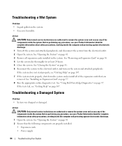
... against electrostatic discharge. 1 Turn off the system and attached peripherals, and disconnect the system from the electrical outlet. 2 Open the system. See "Using Dell PowerEdge Diagnostics" on page 57. 8 Run the appropriate online diagnostic test. Before performing any procedure, see your Product Information Guide for at least 24 hours. ...Troubleshooting a Damaged System Problem • System was dropped or damaged. Action CAUTION: Only trained service technicians are properly installed: • Expansion cards • Power supply 84 Troubleshooting Your System
... against electrostatic discharge. 1 Turn off the system and attached peripherals, and disconnect the system from the electrical outlet. 2 Open the system. See "Using Dell PowerEdge Diagnostics" on page 57. 8 Run the appropriate online diagnostic test. Before performing any procedure, see your Product Information Guide for at least 24 hours. ...Troubleshooting a Damaged System Problem • System was dropped or damaged. Action CAUTION: Only trained service technicians are properly installed: • Expansion cards • Power supply 84 Troubleshooting Your System
Hardware Owner's Manual
Page 86
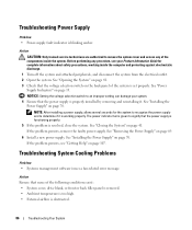
...Closing the System" on page 69. 6 Install a new power supply. See "Removing the Power Supply" on page 41. Troubleshooting Power Supply Problem • Power-supply fault indicator is working inside the system. See "Power Supply Indicators" on page 70. The power indicator turns green to signify that none of the following conditions...Setting the voltage selection switch to an improper setting can damage your Product Information Guide for the system to recognize the power supply and to remove the system cover and access any procedure, see "Getting Help" on page 70. If the problem...
...Closing the System" on page 69. 6 Install a new power supply. See "Removing the Power Supply" on page 41. Troubleshooting Power Supply Problem • Power-supply fault indicator is working inside the system. See "Power Supply Indicators" on page 70. The power indicator turns green to signify that none of the following conditions...Setting the voltage selection switch to an improper setting can damage your Product Information Guide for the system to recognize the power supply and to remove the system cover and access any procedure, see "Getting Help" on page 70. If the problem...
Hardware Owner's Manual
Page 133
... disc. American National Standards Institute. asset tag - beep code - blade - Unless the operating system fails to direct configuration and power management. bootable diskette - cache - When a program makes a request to the configuration of a system. CD - Alternating current....stored on . A module that is used in the U.S. British thermal unit. ambient temperature - ASCII - A battery that includes power supplies and fans. BMC - Baseboard management controller. The modules are mounted into a chassis that maintains system configuration, date, and time ...
... disc. American National Standards Institute. asset tag - beep code - blade - Unless the operating system fails to direct configuration and power management. bootable diskette - cache - When a program makes a request to the configuration of a system. CD - Alternating current....stored on . A module that is used in the U.S. British thermal unit. ambient temperature - ASCII - A battery that includes power supplies and fans. BMC - Baseboard management controller. The modules are mounted into a chassis that maintains system configuration, date, and time ...
Hardware Owner's Manual
Page 139
... pair. VGA and SVGA are installed on a network hub or switch used to connect to file service for example. win.ini file - Uninterruptible power supply. memory, disk drives, or printers, for network clients. video adapter - Windows Powered - Video drivers may be communicated between otherwise unconnected sources. TOE - A port on the hard drive. VDC -
... pair. VGA and SVGA are installed on a network hub or switch used to connect to file service for example. win.ini file - Uninterruptible power supply. memory, disk drives, or printers, for network clients. video adapter - Windows Powered - Video drivers may be communicated between otherwise unconnected sources. TOE - A port on the hard drive. VDC -
Hardware Owner's Manual
Page 142
.../DVD drive, 49 chassis intrusion switch, 72 cooling fans, 67 diskette drive, 45 expansion cards, 57 hard drive, 52 I/O panel, 76 installing (continued) memory, 60 power supply, 70 processor, 65 system battery, 67 system board, 78 tape drive, 49 IRQs avoiding conflicts, 80 line assignments, 80 J jumpers, 101 K keyboard troubleshooting, 81 M memory..., 83 O opening the system, 41 options system setup program, 28 P password admin, 37 disabling, 38, 104 features, 35 system, 35 POST accessing system features, 10 power supply installing, 70 removing, 69 replacing, 70 troubleshooting, 86 142 Index
.../DVD drive, 49 chassis intrusion switch, 72 cooling fans, 67 diskette drive, 45 expansion cards, 57 hard drive, 52 I/O panel, 76 installing (continued) memory, 60 power supply, 70 processor, 65 system battery, 67 system board, 78 tape drive, 49 IRQs avoiding conflicts, 80 line assignments, 80 J jumpers, 101 K keyboard troubleshooting, 81 M memory..., 83 O opening the system, 41 options system setup program, 28 P password admin, 37 disabling, 38, 104 features, 35 system, 35 POST accessing system features, 10 power supply installing, 70 removing, 69 replacing, 70 troubleshooting, 86 142 Index
Hardware Owner's Manual
Page 143
...switch, 72 cooling fans, 67 diskette drive, 45 expansion cards, 57 front drive bezel, 43 I/O panel, 76 memory, 60 replacing (continued) power supply, 70 processor, 65 system board, 78 S safety, 79 SAS controller card installing, 58 troubleshooting, 92 SAS hard drive. SATA hard drive. ...serial port connector, 13 troubleshooting, 82 setup password features, 35 startup accessing system features, 10 status messages systems management, 16 support contacting Dell, 112 system closing, 41 opening, 41 system battery removing, 67 system board connectors, 103 installing, 78 jumpers, 101 removing, 76 ...
...switch, 72 cooling fans, 67 diskette drive, 45 expansion cards, 57 front drive bezel, 43 I/O panel, 76 memory, 60 replacing (continued) power supply, 70 processor, 65 system board, 78 S safety, 79 SAS controller card installing, 58 troubleshooting, 92 SAS hard drive. SATA hard drive. ...serial port connector, 13 troubleshooting, 82 setup password features, 35 startup accessing system features, 10 status messages systems management, 16 support contacting Dell, 112 system closing, 41 opening, 41 system battery removing, 67 system board connectors, 103 installing, 78 jumpers, 101 removing, 76 ...

Hardware Owner's Manual
Page 144
... damaged system, 84 diskette drive, 89 expansion cards, 93 external connections, 80 hard drive, 91 keyboard, 81 memory, 87 microprocessor, 95 mouse, 81 NIC, 83 power supply, 86 SAS controller card, 92 serial port, 82 start-up routine, 79 system battery, 85 system cooling, 86 tape drive, 91 USB device, 82 video...
... damaged system, 84 diskette drive, 89 expansion cards, 93 external connections, 80 hard drive, 91 keyboard, 81 memory, 87 microprocessor, 95 mouse, 81 NIC, 83 power supply, 86 SAS controller card, 92 serial port, 82 start-up routine, 79 system battery, 85 system cooling, 86 tape drive, 91 USB device, 82 video...


