Hardware Owner's Manual
Page 3
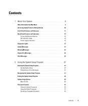
... Features and Indicators 11 Back-Panel Features and Indicators 13 Connecting External Devices 13 NIC Indicator Codes 14 Power Supply Indicators 15 Diagnostic Lights 15 System Messages 16 Warning Messages 25 Diagnostics Messages 26 Alert Messages 26 2 Using the System Setup Program 27 Entering the System Setup Program 27 During System Setup 27...
... Features and Indicators 11 Back-Panel Features and Indicators 13 Connecting External Devices 13 NIC Indicator Codes 14 Power Supply Indicators 15 Diagnostic Lights 15 System Messages 16 Warning Messages 25 Diagnostics Messages 26 Alert Messages 26 2 Using the System Setup Program 27 Entering the System Setup Program 27 During System Setup 27...
Hardware Owner's Manual
Page 12
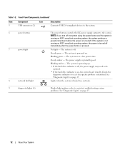
...green - The system is turned off , the power supply may need to see if the specific problem is in troubleshooting system problems. See "Diagnostic Lights" on . Steady amber - The system is powering up. • If the hard drive indicator is off . NOTE: If you turn ... is probably good. Lights when the system is powered on page 15. 12 About Your System The power supply is pressed. Check the diagnostic indicators to be replaced. • If the hard drive indicator is faulty. The system is linked to a network. 9 diagnostic lights (4) Display light-pattern codes to the...
...green - The system is turned off , the power supply may need to see if the specific problem is in troubleshooting system problems. See "Diagnostic Lights" on . Steady amber - The system is powering up. • If the hard drive indicator is off . NOTE: If you turn ... is probably good. Lights when the system is powered on page 15. 12 About Your System The power supply is pressed. Check the diagnostic indicators to be replaced. • If the hard drive indicator is faulty. The system is linked to a network. 9 diagnostic lights (4) Display light-pattern codes to the...
Hardware Owner's Manual
Page 15
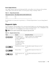
... failure has occurred. Memory failure. a non-highlighted circle indicates the light is set to: 110 V 115 220 V 230 For information on the back panel of two primary voltage inputs. The diagnostic lights are not lit after the system successfully boots to select one of ...you to the operating system. See "Troubleshooting the Microprocessor" on ; A highlighted circle indicates the light is on page 95. NOTE: Once the system completes POST, all diagnostic lights will be set to the proper voltage according to Table 1-4. Power Supply Indicators The voltage selection ...
... failure has occurred. Memory failure. a non-highlighted circle indicates the light is set to: 110 V 115 220 V 230 For information on the back panel of two primary voltage inputs. The diagnostic lights are not lit after the system successfully boots to select one of ...you to the operating system. See "Troubleshooting the Microprocessor" on ; A highlighted circle indicates the light is on page 95. NOTE: Once the system completes POST, all diagnostic lights will be set to the proper voltage according to Table 1-4. Power Supply Indicators The voltage selection ...
Hardware Owner's Manual
Page 79
...Start-Up Routine Look and listen during the system's start-up routine for : A code displayed on the system diagnostic indicators. The CD drive activity indicator. The hard-drive activity indicator. See "Troubleshooting the Video Subsystem" on page ...the procedures, see your system documentation. Start-Up Routine Indications Look/listen for the indications described in Table 4-1. Action See "Diagnostic Lights" on the monitor. Checking the Equipment This section provides troubleshooting procedures for complete information about safety precautions, working inside the computer...
...Start-Up Routine Look and listen during the system's start-up routine for : A code displayed on the system diagnostic indicators. The CD drive activity indicator. The hard-drive activity indicator. See "Troubleshooting the Video Subsystem" on page ...the procedures, see your system documentation. Start-Up Routine Indications Look/listen for the indications described in Table 4-1. Action See "Diagnostic Lights" on the monitor. Checking the Equipment This section provides troubleshooting procedures for complete information about safety precautions, working inside the computer...
Hardware Owner's Manual
Page 83
... If the link indicator does not light, check all cable connections. • If the activity indicator does not light, the network driver files might be damaged or missing. See "Getting Help" on page 107. Action 1 Run the appropriate online diagnostic test. Troubleshooting Your System 83 If... USB device. Remove and reinstall the drivers if applicable. If the problem persists, see "Getting Help" on page 107. See "Using Dell PowerEdge Diagnostics" on page 97. 2 Check the appropriate indicator on page 27. 5 Ensure that the appropriate drivers are installed and the protocols are ...
... If the link indicator does not light, check all cable connections. • If the activity indicator does not light, the network driver files might be damaged or missing. See "Getting Help" on page 107. Action 1 Run the appropriate online diagnostic test. Troubleshooting Your System 83 If... USB device. Remove and reinstall the drivers if applicable. If the problem persists, see "Getting Help" on page 107. See "Using Dell PowerEdge Diagnostics" on page 97. 2 Check the appropriate indicator on page 27. 5 Ensure that the appropriate drivers are installed and the protocols are ...


