Getting Started Guide
Page 5
... disk volume types: simple, spanned, stripped (RAID 0), and mirrored (RAID 1). • Support for 2D graphics. NOTE: DVD devices are supported in the four memory module sockets on the system board; true-color graphics are data only. • Support for the following resolutions: 640 x 480, 800 x 600, 1024 x 768, and 1280 x 1024...
... disk volume types: simple, spanned, stripped (RAID 0), and mirrored (RAID 1). • Support for 2D graphics. NOTE: DVD devices are supported in the four memory module sockets on the system board; true-color graphics are data only. • Support for the following resolutions: 640 x 480, 800 x 600, 1024 x 768, and 1280 x 1024...
Getting Started Guide
Page 10
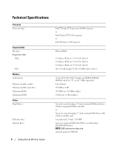
..., Unbuffered, DDR II SDRAM, DIMMs, rated for 533- Technical Specifications Processor Processor type Expansion Bus Bus type Expansion slots PCIe PCI Memory Architecture Memory module sockets Memory module capacities Minimum RAM Maximum RAM Drives Hard Drives Diskette drive Optical drives 8 Getting Started With Your System Intel® Pentium® D processor, E6000...
..., Unbuffered, DDR II SDRAM, DIMMs, rated for 533- Technical Specifications Processor Processor type Expansion Bus Bus type Expansion slots PCIe PCI Memory Architecture Memory module sockets Memory module capacities Minimum RAM Maximum RAM Drives Hard Drives Diskette drive Optical drives 8 Getting Started With Your System Intel® Pentium® D processor, E6000...
Hardware Owner's Manual
Page 30
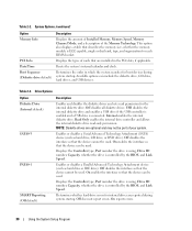
... that the device can be used . This option also displays a table that the device can be used . Determines whether hard-drive errors for each DIMM socket. Table 2-2. Determines the order in the PCI slots, if applicable. Available options can include the diskette drive, CD drive, hard drives, and USB devices...
... that the device can be used . This option also displays a table that the device can be used . Determines whether hard-drive errors for each DIMM socket. Table 2-2. Determines the order in the PCI slots, if applicable. Available options can include the diskette drive, CD drive, hard drives, and USB devices...

Hardware Owner's Manual
Page 61
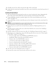
... and disconnect the system from the electrical outlet. Installing and Removing a Memory Module 1 4 3 2 1 memory module 4 memory module socket ejectors (2) 2 alignment key 3 socket 6 Pull up on the system and attached peripherals. The system detects that the new memory does not match the existing configuration information and ...program and check the value for Memory Info to reflect the newly installed memory. See "System Setup Options" on the memory module socket should have changed . If it is correct, skip to step 13. 10 If the memory value is properly seated in the connector...
... and disconnect the system from the electrical outlet. Installing and Removing a Memory Module 1 4 3 2 1 memory module 4 memory module socket ejectors (2) 2 alignment key 3 socket 6 Pull up on the system and attached peripherals. The system detects that the new memory does not match the existing configuration information and ...program and check the value for Memory Info to reflect the newly installed memory. See "System Setup Options" on the memory module socket should have changed . If it is correct, skip to step 13. 10 If the memory value is properly seated in the connector...

Hardware Owner's Manual
Page 64
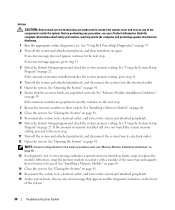
... system board. 6 Carefully pivot the retention latch away from under the release lever latch on the socket connector pads. 7 Lift the processor straight up and out of the socket. Ensure that the socket is pressure-loaded. 5 Open the processor cover by a single edge. Installing and Removing a Processor... 1 7 2 6 3 4 5 1 processor 4 release lever latch 7 release lever 2 retention latch 5 tab 3 socket 6 notched processor edge NOTICE: The retention latch is ready for the new processor. 64 Installing System Components See Figure 3-16. NOTICE: Do not...
... system board. 6 Carefully pivot the retention latch away from under the release lever latch on the socket connector pads. 7 Lift the processor straight up and out of the socket. Ensure that the socket is pressure-loaded. 5 Open the processor cover by a single edge. Installing and Removing a Processor... 1 7 2 6 3 4 5 1 processor 4 release lever latch 7 release lever 2 retention latch 5 tab 3 socket 6 notched processor edge NOTICE: The retention latch is ready for the new processor. 64 Installing System Components See Figure 3-16. NOTICE: Do not...

Hardware Owner's Manual
Page 65
... can damage the system board. 4 Carefully set the processor in the socket frame. NOTE: If you are authorized to the top of the processor. 8 Place the heat sink assembly back onto the heat sink assembly bracket and ...
... can damage the system board. 4 Carefully set the processor in the socket frame. NOTE: If you are authorized to the top of the processor. 8 Place the heat sink assembly back onto the heat sink assembly bracket and ...

Hardware Owner's Manual
Page 67
... from the electrical outlet. 3 Open the system. Ensure that block access to the manufacturer's instructions. You may damage the system board by prying off the socket or by the manufacturer. In this case, you attempt to the system board. 5 Close the system. Installing System Components 67 however, without a battery; Discard used...
... from the electrical outlet. 3 Open the system. Ensure that block access to the manufacturer's instructions. You may damage the system board by prying off the socket or by the manufacturer. In this case, you attempt to the system board. 5 Close the system. Installing System Components 67 however, without a battery; Discard used...

Hardware Owner's Manual
Page 68
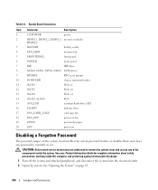
See Figure 3-18. 2 Close the system. Removing and Installing the System Battery 2 1 3 1 battery socket 2 system battery 3 tab Installing the System Battery 1 Install the new battery with the "+" facing up, and press down until it on. 9 Enter the System Setup ..., reconnect the system to release the battery, then lift the battery out of the old battery. For more information, see "Getting Help" on the battery socket to a power source and turn it snaps into place. 5 Press the tab on page 107. 10 Properly dispose of the...
See Figure 3-18. 2 Close the system. Removing and Installing the System Battery 2 1 3 1 battery socket 2 system battery 3 tab Installing the System Battery 1 Install the new battery with the "+" facing up, and press down until it on. 9 Enter the System Setup ..., reconnect the system to release the battery, then lift the battery out of the old battery. For more information, see "Getting Help" on the battery socket to a power source and turn it snaps into place. 5 Press the tab on page 107. 10 Properly dispose of the...

Hardware Owner's Manual
Page 77
... 3-23. System Board Mounting Points 1 2 1 heat sink pivot mount screws (2) 3 2 system board mounting screws (8) 3 system board Installing System Components 77 NOTE: Record the memory-module socket locations to cool before handling. NOTICE: To prevent damaging the processor, do not pry the heat sink off of the memory modules. • SATA hard...
... 3-23. System Board Mounting Points 1 2 1 heat sink pivot mount screws (2) 3 2 system board mounting screws (8) 3 system board Installing System Components 77 NOTE: Record the memory-module socket locations to cool before handling. NOTICE: To prevent damaging the processor, do not pry the heat sink off of the memory modules. • SATA hard...
Hardware Owner's Manual
Page 78
... system board up and out of the chassis. 2 Using a #2 Phillips screwdriver, install the eight screws on the system board that you removed in the same sockets from the INTRUDER connector 8 Close the system.
... system board up and out of the chassis. 2 Using a #2 Phillips screwdriver, install the eight screws on the system board that you removed in the same sockets from the INTRUDER connector 8 Close the system.
Hardware Owner's Manual
Page 88
... memory setting, go to the next step. If the memory modules are populated correctly, continue to the next step. 7 Reseat the memory modules in socket 1 with a module of the same type and capacity that is known to be good. See "Using the System Setup Program" on page 59. ...to its electrical outlet, and turn on the front of the system. 88 Troubleshooting Your System Otherwise, swap the memory module in their sockets. See "Using Dell PowerEdge Diagnostics" on again. If the amount of memory installed still does not match the system memory setting, proceed to the next step. ...
... memory setting, go to the next step. If the memory modules are populated correctly, continue to the next step. 7 Reseat the memory modules in socket 1 with a module of the same type and capacity that is known to be good. See "Using the System Setup Program" on page 59. ...to its electrical outlet, and turn on the front of the system. 88 Troubleshooting Your System Otherwise, swap the memory module in their sockets. See "Using Dell PowerEdge Diagnostics" on again. If the amount of memory installed still does not match the system memory setting, proceed to the next step. ...
Hardware Owner's Manual
Page 104
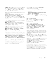
System Board Connectors Item Connector Description 1 12VPOWER power 2 DIMM_1, DIMM_2, DIMM_3, memory modules DIMM_4 3 BATTERY battery socket 4 FAN_MEM memory fan 5 FRONTPANEL front panel 6 POWER main power 7 IDE IDE drive 8 SATA0, SATA1, SATA2, SATA3 SATA drives 9 RTCRST RTC reset jumper 10 INTRUDER chassis ...
System Board Connectors Item Connector Description 1 12VPOWER power 2 DIMM_1, DIMM_2, DIMM_3, memory modules DIMM_4 3 BATTERY battery socket 4 FAN_MEM memory fan 5 FRONTPANEL front panel 6 POWER main power 7 IDE IDE drive 8 SATA0, SATA1, SATA2, SATA3 SATA drives 9 RTCRST RTC reset jumper 10 INTRUDER chassis ...
Hardware Owner's Manual
Page 137
... 0, RAID 1, RAID 5, RAID 10, and RAID 50. RAID - readme file - Glossary 137 PCI - A standard for program instructions and data. Pin grid array. A type of processor socket that controls the interpretation and execution of 16 MB to remove the processor chip. MS-DOS cannot run on a video display. RAC - The system's primary...
... 0, RAID 1, RAID 5, RAID 10, and RAID 50. RAID - readme file - Glossary 137 PCI - A standard for program instructions and data. Pin grid array. A type of processor socket that controls the interpretation and execution of 16 MB to remove the processor chip. MS-DOS cannot run on a video display. RAC - The system's primary...

Hardware Owner's Manual
Page 141
... serial port, 13 USB, 11, 13 video, 13 cooling fans installing, 67 removing, 65 replacing, 67 troubleshooting, 87 D damaged systems troubleshooting, 84 Dell contacting, 112 diagnostics advanced testing options, 98 testing options, 98 when to use, 98 DIMM sockets, 58 diskette drive installing, 45 removing, 44 replacing, 45 troubleshooting, 89 DVD drive.
... serial port, 13 USB, 11, 13 video, 13 cooling fans installing, 67 removing, 65 replacing, 67 troubleshooting, 87 D damaged systems troubleshooting, 84 Dell contacting, 112 diagnostics advanced testing options, 98 testing options, 98 when to use, 98 DIMM sockets, 58 diskette drive installing, 45 removing, 44 replacing, 45 troubleshooting, 89 DVD drive.
