Getting Started Guide
Page 5
...maximum of 533- See the Hardware Owner's Manual. • A minimum of 512 MB of 4 GB DDR II SDRAM memory by installing 512-MB or 1-GB unbuffered ECC memory modules in the following processors: - Up to two supported devices including IDE CD, DVD, CDRW/DVD combination drive, and... video subsystem with an ATI ES1000, 33-MHz PCI video controller. NOTE: Your system supports integrated video only. NOTE: DVD devices are Intel Extended Memory 64 Technology (Intel EM64T) capable. Intel Pentium 4, 600 sequence. width PCIe expansion slot, and one x4 lane- Intel Celeron® D, 300 ...
...maximum of 533- See the Hardware Owner's Manual. • A minimum of 512 MB of 4 GB DDR II SDRAM memory by installing 512-MB or 1-GB unbuffered ECC memory modules in the following processors: - Up to two supported devices including IDE CD, DVD, CDRW/DVD combination drive, and... video subsystem with an ATI ES1000, 33-MHz PCI video controller. NOTE: Your system supports integrated video only. NOTE: DVD devices are Intel Extended Memory 64 Technology (Intel EM64T) capable. Intel Pentium 4, 600 sequence. width PCIe expansion slot, and one x4 lane- Intel Celeron® D, 300 ...
Getting Started Guide
Page 10
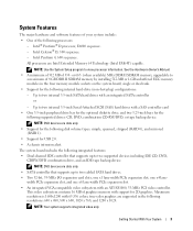
... drives NOTE: DVD devices are data only. external optional USB CD Technical Specifications Processor Processor type Expansion Bus Bus type Expansion slots PCIe PCI Memory Architecture Memory module sockets Memory module capacities Minimum RAM Maximum RAM Drives Hard Drives Diskette drive Optical drives 8 Getting Started With Your System Intel® Pentium® D processor...
... drives NOTE: DVD devices are data only. external optional USB CD Technical Specifications Processor Processor type Expansion Bus Bus type Expansion slots PCIe PCI Memory Architecture Memory module sockets Memory module capacities Minimum RAM Maximum RAM Drives Hard Drives Diskette drive Optical drives 8 Getting Started With Your System Intel® Pentium® D processor...

Getting Started Guide
Page 11
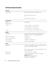
Drives (continued) Tape drive Flash drive Connectors Back NIC Serial USB Video Front USB Internally accessible IDE channel SATA channels Video Video type Video memory Power AC power supply (per power supply) Wattage Voltage Heat dissipation CMOS Backup Battery Physical Height Width Depth Weight (maximum configuration) one optional internal half-...
Drives (continued) Tape drive Flash drive Connectors Back NIC Serial USB Video Front USB Internally accessible IDE channel SATA channels Video Video type Video memory Power AC power supply (per power supply) Wattage Voltage Heat dissipation CMOS Backup Battery Physical Height Width Depth Weight (maximum configuration) one optional internal half-...
Hardware Owner's Manual
Page 4
... Expansion Card 56 Installing an Expansion Card 57 SAS Controller Expansion Card 58 Memory 58 Memory Module Upgrade Kits 59 Memory Module Installation Guidelines 59 Addressing Memory With 4-GB Configurations (Microsoft® Windows® Operating System Only 59 Removing a Memory Module 60 Installing a Memory Module 60 Microprocessor 62 Removing the Processor 62 Replacing the Processor 65...
... Expansion Card 56 Installing an Expansion Card 57 SAS Controller Expansion Card 58 Memory 58 Memory Module Upgrade Kits 59 Memory Module Installation Guidelines 59 Addressing Memory With 4-GB Configurations (Microsoft® Windows® Operating System Only 59 Removing a Memory Module 60 Installing a Memory Module 60 Microprocessor 62 Removing the Processor 62 Replacing the Processor 65...
Hardware Owner's Manual
Page 6
... Troubleshooting a Fan 87 Troubleshooting System Memory 87 Troubleshooting a Diskette Drive 89 Troubleshooting an Optical Drive 90 Troubleshooting an IDE Tape Drive 91 Troubleshooting a Hard Drive 91 Troubleshooting a SAS RAID Controller 92 Troubleshooting Expansion Cards 93 Troubleshooting the Microprocessor 95 5 Running the System Diagnostics 97 Using Dell PowerEdge Diagnostics 97 System Diagnostics Features 97...
... Troubleshooting a Fan 87 Troubleshooting System Memory 87 Troubleshooting a Diskette Drive 89 Troubleshooting an Optical Drive 90 Troubleshooting an IDE Tape Drive 91 Troubleshooting a Hard Drive 91 Troubleshooting a SAS RAID Controller 92 Troubleshooting Expansion Cards 93 Troubleshooting the Microprocessor 95 5 Running the System Diagnostics 97 Using Dell PowerEdge Diagnostics 97 System Diagnostics Features 97...
Hardware Owner's Manual
Page 15
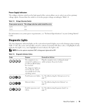
... the system completes POST, all diagnostic lights will be set to the proper voltage according to select one of two primary voltage inputs. Memory failure. See "Troubleshooting System Memory" on the system front panel display error codes during system startup. About Your System 15 a non-highlighted circle indicates the light is in...
... the system completes POST, all diagnostic lights will be set to the proper voltage according to select one of two primary voltage inputs. Memory failure. See "Troubleshooting System Memory" on the system front panel display error codes during system startup. About Your System 15 a non-highlighted circle indicates the light is in...
Hardware Owner's Manual
Page 16
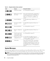
... 107. Possible system resource See "Troubleshooting IRQ Assignment configuration error. Diagnostic Indicator Codes (continued) Code Causes Possible video failure. No memory modules detected. See "Getting Help" on page 87. Conflicts" on page 107. Other failure. If the problem persists, see ...appear on page 107. See "Hard Drives" on page 51 or "Diskette Drive" on page 79 for each message. Memory configuration See "Troubleshooting System Memory" on page 82. Diskette drive or hard drive failure. System board failure. See "Troubleshooting Your System" on page 44 ...
... 107. Possible system resource See "Troubleshooting IRQ Assignment configuration error. Diagnostic Indicator Codes (continued) Code Causes Possible video failure. No memory modules detected. See "Getting Help" on page 87. Conflicts" on page 107. Other failure. If the problem persists, see ...appear on page 107. See "Hard Drives" on page 51 or "Diskette Drive" on page 79 for each message. Memory configuration See "Troubleshooting System Memory" on page 82. Diskette drive or hard drive failure. System board failure. See "Troubleshooting Your System" on page 44 ...

Hardware Owner's Manual
Page 17
... 107. The system was due to voltage regulator failure See "Getting Help" on page 27. Alert! Unable to initialize all installed memory One or more memory modules might See "Troubleshooting System Memory" be faulty or improperly seated. Ensure heatsink and shroud assembly are properly attached. The system will halt at the Problems" on...
... 107. The system was due to voltage regulator failure See "Getting Help" on page 27. Alert! Unable to initialize all installed memory One or more memory modules might See "Troubleshooting System Memory" be faulty or improperly seated. Ensure heatsink and shroud assembly are properly attached. The system will halt at the Problems" on...

Hardware Owner's Manual
Page 18
...) Message Alert! After the operating system is not installed correctly. boot routine three consecutive times for a list of system memory. Alert! Alert! Alert! Previous attempts at checkpoint [nnnn]. Previous Processor Thermal Failure Causes Corrective Actions The processor cooling fan...expansion card. Alert! See "Troubleshooting System Cooling Problems" on page 86 and "Microprocessor" on page 86. Use only Dell supported processors. Incompatible processor detected. OS Install Mode enabled. The OS Install Mode option in resolving this problem, please ...
...) Message Alert! After the operating system is not installed correctly. boot routine three consecutive times for a list of system memory. Alert! Alert! Alert! Previous attempts at checkpoint [nnnn]. Previous Processor Thermal Failure Causes Corrective Actions The processor cooling fan...expansion card. Alert! See "Troubleshooting System Cooling Problems" on page 86 and "Microprocessor" on page 86. Use only Dell supported processors. Incompatible processor detected. OS Install Mode enabled. The OS Install Mode option in resolving this problem, please ...
Hardware Owner's Manual
Page 19
...Your System 19 Also, ensure that you have spelled the command correctly, have put spaces in the proper place, and have used . Uncorrectable Memory Error Previously Detected... See "Troubleshooting a Diskette Drive" on page 89 or "Troubleshooting a Hard Drive" on page 93. Bad error-correction code.... See "Troubleshooting a Hard Drive" on disk read The diskette or hard-drive controller detected an uncorrectable read error. See "Troubleshooting System Memory" on -board devices. bb/dd/f: Error allocating IRQ for PCI Device bb/dd/f: Error allocating I/O BAR for PCI Device bb/dd/f:...
...Your System 19 Also, ensure that you have spelled the command correctly, have put spaces in the proper place, and have used . Uncorrectable Memory Error Previously Detected... See "Troubleshooting a Diskette Drive" on page 89 or "Troubleshooting a Hard Drive" on page 93. Bad error-correction code.... See "Troubleshooting a Hard Drive" on disk read The diskette or hard-drive controller detected an uncorrectable read error. See "Troubleshooting System Memory" on -board devices. bb/dd/f: Error allocating IRQ for PCI Device bb/dd/f: Error allocating I/O BAR for PCI Device bb/dd/f:...
Hardware Owner's Manual
Page 20
...Faulty keyboard controller (faulty system board). For the operating system, run the appropriate utility to the open position. See "Troubleshooting System Memory" on page 89. Diskette read the data. See "Troubleshooting a Diskette Drive" on page 87. Drive not ready No diskette is... be faulty or improperly seated. The diskette in the drive. Reinstall the memory modules and, if necessary, replace them. Diskette write protected The diskette is faulty. Decreasing available memory One or more memory modules might not on page 89. Diskette drive 0 seek failure A cable...
...Faulty keyboard controller (faulty system board). For the operating system, run the appropriate utility to the open position. See "Troubleshooting System Memory" on page 89. Diskette read the data. See "Troubleshooting a Diskette Drive" on page 87. Drive not ready No diskette is... be faulty or improperly seated. The diskette in the drive. Reinstall the memory modules and, if necessary, replace them. Diskette write protected The diskette is faulty. Decreasing available memory One or more memory modules might not on page 89. Diskette drive 0 seek failure A cable...

Hardware Owner's Manual
Page 21
... Also, see "Troubleshooting a Hard Drive" on page 81. Memory address line failure at address, read value expecting value A memory module might be faulty or improperly seated. See "Troubleshooting System Memory" on page 91. Memory allocation error The software you are attempting to run SETUP program ...System Diagnostics" on page 27. See "Using the System Setup Program" on page 97. Keyboard failure Keyboard fuse has failed. Reinstall the memory modules and, if necessary, replace them. If the error message appears again, see "Troubleshooting a Hard Drive" on page 87. See "...
... Also, see "Troubleshooting a Hard Drive" on page 81. Memory address line failure at address, read value expecting value A memory module might be faulty or improperly seated. See "Troubleshooting System Memory" on page 91. Memory allocation error The software you are attempting to run SETUP program ...System Diagnostics" on page 27. See "Using the System Setup Program" on page 97. Keyboard failure Keyboard fuse has failed. Reinstall the memory modules and, if necessary, replace them. If the error message appears again, see "Troubleshooting a Hard Drive" on page 87. See "...

Hardware Owner's Manual
Page 22
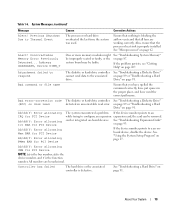
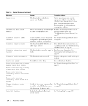
... sequence information. System Messages (continued) Message Causes Corrective Actions Memory data line failure at address, read value expecting value Memory double word logic failure at address, read value expecting value A memory module might be faulty or improperly seated. Please refer to ... disk is not supported on page 87. See "Troubleshooting System Memory" on this system. problem persists, see "Troubleshooting does not match the memory installed System Memory" on page 27. 22 About Your System Memory type or speed is in the system. If the hard drive...
... sequence information. System Messages (continued) Message Causes Corrective Actions Memory data line failure at address, read value expecting value Memory double word logic failure at address, read value expecting value A memory module might be faulty or improperly seated. Please refer to ... disk is not supported on page 87. See "Troubleshooting System Memory" on this system. problem persists, see "Troubleshooting does not match the memory installed System Memory" on page 27. 22 About Your System Memory type or speed is in the system. If the hard drive...

Hardware Owner's Manual
Page 23
... operating system installed on page 97. If the problem persists, see "Getting Help" on the system board might have to use first See "Troubleshooting System Memory" on page 91. The operating system is not supported on page 107. Close all windows and open . If the problem persists, see "Troubleshooting a Diskette Drive... Messages (continued) Message No boot sector on hard-disk drive No timer tick interrupt Non-system disk or disk error Not a boot diskette Not enough memory or resources. About Your System 23 Table 1-6.
... operating system installed on page 97. If the problem persists, see "Getting Help" on the system board might have to use first See "Troubleshooting System Memory" on page 91. The operating system is not supported on page 107. Close all windows and open . If the problem persists, see "Troubleshooting a Diskette Drive... Messages (continued) Message No boot sector on hard-disk drive No timer tick interrupt Non-system disk or disk error Not a boot diskette Not enough memory or resources. About Your System 23 Table 1-6.
Hardware Owner's Manual
Page 24
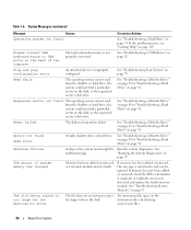
...from the diskette or hard drive, the system could not find a particular sector on the back of system memory has changed Memory has been added or removed, or a memory module may be faulty. Shutdown failure A chip on page 91. Table 1-6. System Messages (continued) Message Causes... or removed, this message is not properly connected. Requested sector not found Seek error A faulty diskette drive or hard drive. See "Troubleshooting System Memory" on page 82. See "Troubleshooting a USB Device" on page 87. See "Troubleshooting a Diskette Drive" on page 89 or "Troubleshooting a ...
...from the diskette or hard drive, the system could not find a particular sector on the back of system memory has changed Memory has been added or removed, or a memory module may be faulty. Shutdown failure A chip on page 91. Table 1-6. System Messages (continued) Message Causes... or removed, this message is not properly connected. Requested sector not found Seek error A faulty diskette drive or hard drive. See "Troubleshooting System Memory" on page 82. See "Troubleshooting a USB Device" on page 87. See "Troubleshooting a Diskette Drive" on page 89 or "Troubleshooting a ...

Hardware Owner's Manual
Page 27
... send a message the first time you press , allow the system to finish booting, and then restart your system to exit the program. NOTE: After installing a memory upgrade, it is booting, make a note of the message and suggestions for future reference. NOTE: To ensure an orderly system shutdown, see the following message...
... send a message the first time you press , allow the system to finish booting, and then restart your system to exit the program. NOTE: After installing a memory upgrade, it is booting, make a note of the message and suggestions for future reference. NOTE: To ensure an orderly system shutdown, see the following message...
Hardware Owner's Manual
Page 30
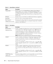
... the BIOS, and Link Speed. Off disables the interface so that the device can be part of cards that describes the memory size, whether the memory module is controlled by the BIOS, and Link Speed. On enables the interface so that the device cannot be used .... for each DIMM socket. Table 2-2. System Options (continued) Option Memory Info PCI Info Date/Time Boot Sequence (Diskette drive default) Description Displays the amount of Installed Memory, Memory Speed, Memory Channel Mode, and a description of the Memory Technology. Off disables the interface so that the device can include ...
... the BIOS, and Link Speed. Off disables the interface so that the device can be part of cards that describes the memory size, whether the memory module is controlled by the BIOS, and Link Speed. On enables the interface so that the device cannot be used .... for each DIMM socket. Table 2-2. System Options (continued) Option Memory Info PCI Info Date/Time Boot Sequence (Diskette drive default) Description Displays the amount of Installed Memory, Memory Speed, Memory Channel Mode, and a description of the Memory Technology. Off disables the interface so that the device can include ...

Hardware Owner's Manual
Page 33
... features. On w/ Boot to NIC enables the NIC to not use the Auto Power Time setting to turn on . Specifies whether or not Execute Disable Memory Protection Technology is reported during start-up the system and boot from the Suspend, Hibernate, or Off states. Table 2-7. Using the System Setup Program 33...
... features. On w/ Boot to NIC enables the NIC to not use the Auto Power Time setting to turn on . Specifies whether or not Execute Disable Memory Protection Technology is reported during start-up the system and boot from the Suspend, Hibernate, or Off states. Table 2-7. Using the System Setup Program 33...

Hardware Owner's Manual
Page 39
... system components: • Front drive bezel • Diskette drive • Optical and tape drives • Hard drives • Expansion cards • SAS controller card • Memory • Microprocessor • Cooling fans • System battery • Power supply • Chassis intrusion switch • Bezel • I/O panel • System board Recommended Tools You...
... system components: • Front drive bezel • Diskette drive • Optical and tape drives • Hard drives • Expansion cards • SAS controller card • Memory • Microprocessor • Cooling fans • System battery • Power supply • Chassis intrusion switch • Bezel • I/O panel • System board Recommended Tools You...

Hardware Owner's Manual
Page 40
... hard drives (2) processor cooling fan 3 power supply 6 card cage fan 9 3.5-inch drive bay The system board can accommodate one processor, five expansion cards, and four memory modules.
... hard drives (2) processor cooling fan 3 power supply 6 card cage fan 9 3.5-inch drive bay The system board can accommodate one processor, five expansion cards, and four memory modules.


