Information Update
Page 1
Trademarks used in trademarks and trade names other than its own. Dell™ PowerEdge™ SC440 Systems Information Update Processor Specifications Table 1 updates the processor specifications listed in Malaysia. All rights reserved. Dell Inc. Reproduction in any proprietary interest in this document to refer to change without the written permission of Intel Corporation. Intel, Xeon, Celeron, and...
Trademarks used in trademarks and trade names other than its own. Dell™ PowerEdge™ SC440 Systems Information Update Processor Specifications Table 1 updates the processor specifications listed in Malaysia. All rights reserved. Dell Inc. Reproduction in any proprietary interest in this document to refer to change without the written permission of Intel Corporation. Intel, Xeon, Celeron, and...
Getting Started Guide
Page 5
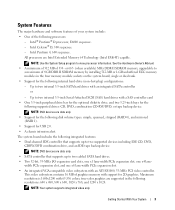
...following resolutions: 640 x 480, 800 x 600, 1024 x 768, and 1280 x 1024. NOTE: Your system supports integrated video only. All processors are supported in the four memory module sockets on the system board; or 667- (when available) MHz DDR II SDRAM memory, upgradable to two... up to two supported devices including IDE CD, DVD, CDRW/DVD combination drive, and an IDE tape backup device. The system board includes the following processors: - Intel Celeron® D, 300 sequence. - width PCIe expansion slot, and one x4 lane- Getting Started With Your System 3 See the Hardware...
...following resolutions: 640 x 480, 800 x 600, 1024 x 768, and 1280 x 1024. NOTE: Your system supports integrated video only. All processors are supported in the four memory module sockets on the system board; or 667- (when available) MHz DDR II SDRAM memory, upgradable to two... up to two supported devices including IDE CD, DVD, CDRW/DVD combination drive, and an IDE tape backup device. The system board includes the following processors: - Intel Celeron® D, 300 sequence. - width PCIe expansion slot, and one x4 lane- Getting Started With Your System 3 See the Hardware...
Getting Started Guide
Page 10
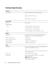
... optional 2.5-inch, 1.44-MB up to two optional IDE CD, DVD, or combination CD-RW/DVD drives NOTE: DVD devices are data only. Technical Specifications Processor Processor type Expansion Bus Bus type Expansion slots PCIe PCI Memory Architecture Memory module sockets Memory module capacities Minimum RAM Maximum RAM Drives Hard Drives Diskette...
... optional 2.5-inch, 1.44-MB up to two optional IDE CD, DVD, or combination CD-RW/DVD drives NOTE: DVD devices are data only. Technical Specifications Processor Processor type Expansion Bus Bus type Expansion slots PCIe PCI Memory Architecture Memory module sockets Memory module capacities Minimum RAM Maximum RAM Drives Hard Drives Diskette...
Hardware Owner's Manual
Page 4
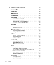
... Addressing Memory With 4-GB Configurations (Microsoft® Windows® Operating System Only 59 Removing a Memory Module 60 Installing a Memory Module 60 Microprocessor 62 Removing the Processor 62 Replacing the Processor 65 4 Contents
... Addressing Memory With 4-GB Configurations (Microsoft® Windows® Operating System Only 59 Removing a Memory Module 60 Installing a Memory Module 60 Microprocessor 62 Removing the Processor 62 Replacing the Processor 65 4 Contents
Hardware Owner's Manual
Page 15
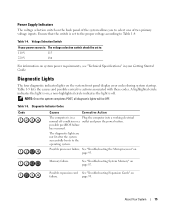
... 15 a non-highlighted circle indicates the light is on system power requirements, see "Technical Specifications" in a Plug the computer into a working electrical normal off . Possible processor failure. See "Troubleshooting System Memory" on page 95. Table 1-5. possible pre-BIOS failure has occurred. Ensure that the switch is : The voltage selection switch should...
... 15 a non-highlighted circle indicates the light is on system power requirements, see "Technical Specifications" in a Plug the computer into a working electrical normal off . Possible processor failure. See "Troubleshooting System Memory" on page 95. Table 1-5. possible pre-BIOS failure has occurred. Ensure that the switch is : The voltage selection switch should...

Hardware Owner's Manual
Page 17
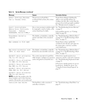
...1-6. A card-cage fan is low Replace the battery. See Figure 3-15. Previous reboot was not found The application that the processor cooling fan is the fan assembly is missing an essential file. Information only. System Messages Message Causes Corrective Actions A filename cannot contain... System Memory" be faulty or improperly seated. See your Product Information Guide for installation instructions. CPU fan not detected The processor cooling fan is faulty or Ensure that you are properly attached. See "Troubleshooting the System Battery" on page 87. Chipset heat...
...1-6. A card-cage fan is low Replace the battery. See Figure 3-15. Previous reboot was not found The application that the processor cooling fan is the fan assembly is missing an essential file. Information only. System Messages Message Causes Corrective Actions A filename cannot contain... System Memory" be faulty or improperly seated. See your Product Information Guide for installation instructions. CPU fan not detected The processor cooling fan is faulty or Ensure that you are properly attached. See "Troubleshooting the System Battery" on page 87. Chipset heat...

Hardware Owner's Manual
Page 18
...! Amount of system memory. See "Troubleshooting System Cooling Problems" on page 86 and "Microprocessor" on page 107. Use only Dell supported processors. Error initializing PCI Express slot n (or bridge). Alert! Alert! boot routine three consecutive times for a list of available ...Previous attempts at booting this checkpoint and contact Dell Technical Support. See "Troubleshooting System Cooling Problems" on page 62. 18 About Your System Alert! OS Install Mode enabled. Alert! Ensure that the processor heat sink is properly installed. The OS ...
...! Amount of system memory. See "Troubleshooting System Cooling Problems" on page 86 and "Microprocessor" on page 107. Use only Dell supported processors. Error initializing PCI Express slot n (or bridge). Alert! Alert! boot routine three consecutive times for a list of available ...Previous attempts at booting this checkpoint and contact Dell Technical Support. See "Troubleshooting System Cooling Problems" on page 62. 18 About Your System Alert! OS Install Mode enabled. Alert! Ensure that the processor heat sink is properly installed. The OS ...
Hardware Owner's Manual
Page 19
... diskette or hard-drive controller detected an uncorrectable read error. All numbers are working correctly. Ensure that the processor heat sink is defective. Alert! If the device number points to Thermal Event The processor or hard drive overheated the last time the system was used the correct pathname. Previous Shutdown Due to...
... diskette or hard-drive controller detected an uncorrectable read error. All numbers are working correctly. Ensure that the processor heat sink is defective. Alert! If the device number points to Thermal Event The processor or hard drive overheated the last time the system was used the correct pathname. Previous Shutdown Due to...

Hardware Owner's Manual
Page 29
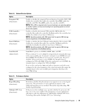
... 2-9 lists the options and descriptions for the processor installed in the system: Processor Type, Processor Clock Speed, Processor Bus Speed, Processor Cache Size, Processor ID number, whether the processor is Multiple Core Capable, or Hyperthreading Capable, and if the processor has 64-bit Technology. Table 2-2. NOTE:... The System Setup program defaults are listed under their respective options, where applicable. System Options Option System Info Processor Info Description Displays the System name, BIOS Version number, BIOS Date, Service Tag, Express Service Code, and Asset ...
... 2-9 lists the options and descriptions for the processor installed in the system: Processor Type, Processor Clock Speed, Processor Bus Speed, Processor Cache Size, Processor ID number, whether the processor is Multiple Core Capable, or Hyperthreading Capable, and if the processor has 64-bit Technology. Table 2-2. NOTE:... The System Setup program defaults are listed under their respective options, where applicable. System Options Option System Info Processor Info Description Displays the System name, BIOS Version number, BIOS Date, Service Tag, Express Service Code, and Asset ...
Hardware Owner's Manual
Page 31
...default) Multiple CPU Core (On default) Description Determines whether the physical processor appears as one or two cores enabled. If the processor has multiple cores, specifies whether the processor will recognize USB storage devices regardless of some applications improve with USB support...Serial Port #1 (Auto default) Description Enables or disables the integrated Network Interface Controller (NIC). NOTE: Operating systems with additional logical processors installed. On enables the controller. If both addresses are COM1, COM3, Auto, and Off. Enables or disables the front USB...
...default) Multiple CPU Core (On default) Description Determines whether the physical processor appears as one or two cores enabled. If the processor has multiple cores, specifies whether the processor will recognize USB storage devices regardless of some applications improve with USB support...Serial Port #1 (Auto default) Description Enables or disables the integrated Network Interface Controller (NIC). NOTE: Operating systems with additional logical processors installed. On enables the controller. If both addresses are COM1, COM3, Auto, and Off. Enables or disables the front USB...
Hardware Owner's Manual
Page 32
... NOTE: See "Using the System Password" on page 37 for its supported features. Some operating systems will support. If the processor supports Enhanced Speed Step Technology, specifies whether the option is not visible. Security Options Option Unlock Setup Admin Password (Not Set default...Options (continued) Option Limit CPUID Speed Step (Off default) HDD Acoustic Mode (Performance default) Description Limits the maximum value the processor standard CPUID function will not complete installation when the maximum CPUID is used for instructions on assigning a setup password and using or...
... NOTE: See "Using the System Password" on page 37 for its supported features. Some operating systems will support. If the processor supports Enhanced Speed Step Technology, specifies whether the option is not visible. Security Options Option Unlock Setup Admin Password (Not Set default...Options (continued) Option Limit CPUID Speed Step (Off default) HDD Acoustic Mode (Performance default) Description Limits the maximum value the processor standard CPUID function will not complete installation when the maximum CPUID is used for instructions on assigning a setup password and using or...

Hardware Owner's Manual
Page 40
... Inside the System 3 2 1 4 9 8 7 5 6 1 5.25-inch drive bays (2) 2 4 system board 5 7 heatsink and shroud assembly 8 drive cage hard drives (2) processor cooling fan 3 power supply 6 card cage fan 9 3.5-inch drive bay The system board can accommodate one processor, five expansion cards, and four memory modules. The hard drive bays provide space for SAS hard drives...
... Inside the System 3 2 1 4 9 8 7 5 6 1 5.25-inch drive bays (2) 2 4 system board 5 7 heatsink and shroud assembly 8 drive cage hard drives (2) processor cooling fan 3 power supply 6 card cage fan 9 3.5-inch drive bay The system board can accommodate one processor, five expansion cards, and four memory modules. The hard drive bays provide space for SAS hard drives...
Hardware Owner's Manual
Page 59
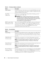
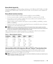
...upgrade, keep them separate from any new memory modules that are installed in connectors DIMM_1 and DIMM_2, and then DIMM_3 and DIMM_4. • If a processor with a slower front-side bus rating than 4 GB. Memory Module Installation Guidelines • If only one memory module is installed, it must be ... one memory module is installed, the memory modules must be installed in pairs of address space; Current operating systems can purchase memory upgrade kits from Dell. Memory Configuration Guidelines Total Memory 512 MB 1 GB 2 GB 2 GB 3 GB 4 GB DIMM_1 512 MB 512 MB 512 MB 1 GB 1 GB 1...
...upgrade, keep them separate from any new memory modules that are installed in connectors DIMM_1 and DIMM_2, and then DIMM_3 and DIMM_4. • If a processor with a slower front-side bus rating than 4 GB. Memory Module Installation Guidelines • If only one memory module is installed, it must be ... one memory module is installed, the memory modules must be installed in pairs of address space; Current operating systems can purchase memory upgrade kits from Dell. Memory Configuration Guidelines Total Memory 512 MB 1 GB 2 GB 2 GB 3 GB 4 GB DIMM_1 512 MB 512 MB 512 MB 1 GB 1 GB 1...

Hardware Owner's Manual
Page 62
...system. 11 Open the system. See "Running the System Diagnostics" on page 41. 12 Ensure that they have had sufficient time to the processor cooling fan housing. See "Opening the System" on page 41. 3 Using a #2 Phillips screwdriver, loosen the two captive screws holding the ...heat sink and shroud assembly in a land grid array (LGA) package. Removing the Processor CAUTION: Only trained service technicians are authorized to remove the system cover and access any procedure, see your Product Information Guide for complete information...
...system. 11 Open the system. See "Running the System Diagnostics" on page 41. 12 Ensure that they have had sufficient time to the processor cooling fan housing. See "Opening the System" on page 41. 3 Using a #2 Phillips screwdriver, loosen the two captive screws holding the ...heat sink and shroud assembly in a land grid array (LGA) package. Removing the Processor CAUTION: Only trained service technicians are authorized to remove the system cover and access any procedure, see your Product Information Guide for complete information...

Hardware Owner's Manual
Page 63
Figure 3-15. Installing and Removing the Heat Sink 1 2 4 1 heatsink and shroud assembly 2 4 processor cooling fan assembly bracket 3 3 captive screws (2) Installing System Components 63
Figure 3-15. Installing and Removing the Heat Sink 1 2 4 1 heatsink and shroud assembly 2 4 processor cooling fan assembly bracket 3 3 captive screws (2) Installing System Components 63

Hardware Owner's Manual
Page 64
.... Then, pull the lever back to the processor's delicate connections. Installing and Removing a Processor 1 7 2 6 3 4 5 1 processor 4 release lever latch 7 release lever 2 retention latch 5 tab 3 socket 6 notched processor edge NOTICE: The retention latch is ready for the new processor. 64 Installing System Components Figure 3-16. NOTICE...the latch does not quickly open and strike the processor or system board. 6 Carefully pivot the retention latch away from under the release lever latch on the socket connector pads. 7 Lift the processor straight up and out of the socket. Leave...
.... Then, pull the lever back to the processor's delicate connections. Installing and Removing a Processor 1 7 2 6 3 4 5 1 processor 4 release lever latch 7 release lever 2 retention latch 5 tab 3 socket 6 notched processor edge NOTICE: The retention latch is ready for the new processor. 64 Installing System Components Figure 3-16. NOTICE...the latch does not quickly open and strike the processor or system board. 6 Carefully pivot the retention latch away from under the release lever latch on the socket connector pads. 7 Lift the processor straight up and out of the socket. Leave...

Hardware Owner's Manual
Page 65
... the system cover and access any procedure, see your Product Information Guide for the card cage. NOTE: If you are removing the larger processor cooling fan, you apply new thermal grease. Removing the Cooling Fans CAUTION: Only trained service technicians are authorized to the top of the ...then tighten them to secure the heat sink assembly to the electrical outlet, and turn on the system and attached peripherals. See "Removing the Processor" on page 41. NOTICE: Ensure that you must first remove the heat sink and shroud assembly. Applying new thermal grease is seated correctly, ...
... the system cover and access any procedure, see your Product Information Guide for the card cage. NOTE: If you are removing the larger processor cooling fan, you apply new thermal grease. Removing the Cooling Fans CAUTION: Only trained service technicians are authorized to the top of the ...then tighten them to secure the heat sink assembly to the electrical outlet, and turn on the system and attached peripherals. See "Removing the Processor" on page 41. NOTICE: Ensure that you must first remove the heat sink and shroud assembly. Applying new thermal grease is seated correctly, ...

Hardware Owner's Manual
Page 66
b Slide the fan toward the back panel and lift the fan out. Removing and Installing the Cooling Fans 2 1 3 4 6 5 1 processor cooling fan 2 release tab for processor fan 3 connector for processor fan (CPU_CAGE) 4 connector for card cage fan 5 release tab for card cage fan 6 card cage fan (FAN_CARD_CAGE) 66 Installing System Components 3... you are removing the smaller card cage fan (see Figure 3-17): a Remove the heat sink and shroud assembly. Do not remove the processor, however. b Press the release tab that attaches the fan to the chassis. Figure 3-17. See "Removing the...
b Slide the fan toward the back panel and lift the fan out. Removing and Installing the Cooling Fans 2 1 3 4 6 5 1 processor cooling fan 2 release tab for processor fan 3 connector for processor fan (CPU_CAGE) 4 connector for card cage fan 5 release tab for card cage fan 6 card cage fan (FAN_CARD_CAGE) 66 Installing System Components 3... you are removing the smaller card cage fan (see Figure 3-17): a Remove the heat sink and shroud assembly. Do not remove the processor, however. b Press the release tab that attaches the fan to the chassis. Figure 3-17. See "Removing the...

Hardware Owner's Manual
Page 67
... Setup program and reset the configuration options. CAUTION: A new battery can last several years. Before performing any procedure, see "Removing the Processor" on page 62). 4 Reconnect the fan power cable to touch the system board with the object. Installing System Components 67 In this case..., you replaced the larger processor cooling fan, replace the heat sink and shroud assembly (see your system without a battery, the configuration information is erased if the system...
... Setup program and reset the configuration options. CAUTION: A new battery can last several years. Before performing any procedure, see "Removing the Processor" on page 62). 4 Reconnect the fan power cable to touch the system board with the object. Installing System Components 67 In this case..., you replaced the larger processor cooling fan, replace the heat sink and shroud assembly (see your system without a battery, the configuration information is erased if the system...

Hardware Owner's Manual
Page 69
... pinched or crimped. 4 Remove the heat sink and shroud assembly. Power Supply Removing the Power Supply CAUTION: Only trained service technicians are adjacent to the processor cooling fan housing. These captive screws are authorized to remove the system cover and access any procedure, see your system configuration, disconnect the following power...
... pinched or crimped. 4 Remove the heat sink and shroud assembly. Power Supply Removing the Power Supply CAUTION: Only trained service technicians are adjacent to the processor cooling fan housing. These captive screws are authorized to remove the system cover and access any procedure, see your system configuration, disconnect the following power...


