Quick Reference Guide
Page 5
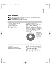
... installed on page 46), or access your documentation. NOTE: Drivers and documentation updates can use the CD to reinstall drivers (see "Using the Drivers and Utilities CD" on page 58), run the Dell Diagnostics (see "Dell Diagnostics" on your computer. You can be available in certain countries. Dell™ OptiPlex™ User's Guide Microsoft Windows XP Help and Support Center 1 Click Start→ Help and Support→ Dell User and System Guides→ System Guides. 2 Click the User's Guide...
... installed on page 46), or access your documentation. NOTE: Drivers and documentation updates can use the CD to reinstall drivers (see "Using the Drivers and Utilities CD" on page 58), run the Dell Diagnostics (see "Dell Diagnostics" on your computer. You can be available in certain countries. Dell™ OptiPlex™ User's Guide Microsoft Windows XP Help and Support Center 1 Click Start→ Help and Support→ Dell User and System Guides→ System Guides. 2 Click the User's Guide...
Quick Reference Guide
Page 7
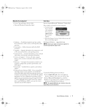
... your computer, you use support.dell.co m or contact support. • Enter the Express Service Code to view the appropriate support site. • Community - Contact information, service call status, support history, service contract, and online discussions with other Dell customers • Upgrades - updates for your operating system and support for drives, and USB devices. Upgrade information for correct the keyword Desktop System Software. Certified drivers, patches, and software updates • Desktop System Software (DSS)- Service call and order...
... your computer, you use support.dell.co m or contact support. • Enter the Express Service Code to view the appropriate support site. • Community - Contact information, service call status, support history, service contract, and online discussions with other Dell customers • Upgrades - updates for your operating system and support for drives, and USB devices. Upgrade information for correct the keyword Desktop System Software. Certified drivers, patches, and software updates • Desktop System Software (DSS)- Service call and order...
Quick Reference Guide
Page 9
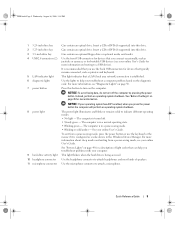
... Windows Device Manager. Use the headphone connector to attach a microphone. Quick Reference Guide 9 Use the front USB connectors for more information. This light indicates that you troubleshoot problems with your computer. Press this button to indicate different operating modes: • No light - NOTICE: To avoid losing data, do not turn on the diagnostic code. To exit from a power-saving mode, see your online User's Guide for devices that a LAN (local area network) connection is configured as a wake device in a power-saving mode...
... Windows Device Manager. Use the headphone connector to attach a microphone. Quick Reference Guide 9 Use the front USB connectors for more information. This light indicates that you troubleshoot problems with your computer. Press this button to indicate different operating modes: • No light - NOTICE: To avoid losing data, do not turn on the diagnostic code. To exit from a power-saving mode, see your online User's Guide for devices that a LAN (local area network) connection is configured as a wake device in a power-saving mode...
Quick Reference Guide
Page 11
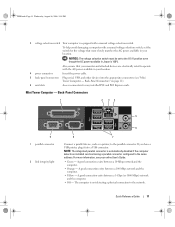
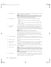
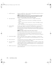
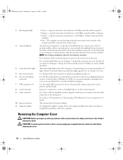
... 11). 6 card slots Access connectors for the voltage that your monitor and attached devices are electrically rated to operate with a manual voltage-selection switch. Mini Tower Computer - Quick Reference Guide 11 book.book Page 11 Wednesday, August 16, 2006 3:18 PM 3 voltage selection switch Your computer is equipped with the AC power available in your location. 4 power connector Insert the power cable. 5 back-panel connectors Plug serial, USB, and other devices into a USB connector. NOTICE...
... 11). 6 card slots Access connectors for the voltage that your monitor and attached devices are electrically rated to operate with a manual voltage-selection switch. Mini Tower Computer - Quick Reference Guide 11 book.book Page 11 Wednesday, August 16, 2006 3:18 PM 3 voltage selection switch Your computer is equipped with the AC power available in your location. 4 power connector Insert the power cable. 5 back-panel connectors Plug serial, USB, and other devices into a USB connector. NOTICE...
Quick Reference Guide
Page 12
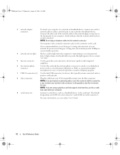
... make this connector will be in /microphone connector to the serial port. NOTE: If you use the y-cable that typically remain connected, such as a cassette player, CD player, or VCR.; The default designations are using a graphics card that supports dual monitors, use Category 5 wiring and connectors for your network. NOTE: Do not plug a telephone cable into a sound or telephony program. 7 USB 2.0 connectors (6) Use the back USB connectors for serial connector 2. Do not remove the cap. NOTE: If you must use the connector...
... make this connector will be in /microphone connector to the serial port. NOTE: If you use the y-cable that typically remain connected, such as a cassette player, CD player, or VCR.; The default designations are using a graphics card that supports dual monitors, use Category 5 wiring and connectors for your network. NOTE: Do not plug a telephone cable into a sound or telephony program. 7 USB 2.0 connectors (6) Use the back USB connectors for serial connector 2. Do not remove the cap. NOTE: If you must use the connector...
Quick Reference Guide
Page 14
... different operating states: • No light - To exit from a power-saving mode, see "Diagnostic Lights" on the diagnostic code. Use the headphone connector to help you troubleshoot a computer problem based on page 50. The computer is configured as a wake device in a power-saving mode. • Blinking or solid amber - The computer is being accessed. For more information about sleep modes and exiting from a power-saving mode, press the power button or use the keyboard or the mouse if...
... different operating states: • No light - To exit from a power-saving mode, see "Diagnostic Lights" on the diagnostic code. Use the headphone connector to help you troubleshoot a computer problem based on page 50. The computer is configured as a wake device in a power-saving mode. • Blinking or solid amber - The computer is being accessed. For more information about sleep modes and exiting from a power-saving mode, press the power button or use the keyboard or the mouse if...
Quick Reference Guide
Page 15
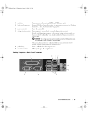
... with a manual voltage selection switch. Back-Panel Connectors 1 2 34 9 8 5 6 7 Quick Reference Guide 15 NOTICE: The voltage selection switch must be set the switch for any installed PCI and PCI Express cards. 2 back-panel connectors Plug serial, USB, and other devices into the appropriate connectors (see "Desktop Computer - Back-Panel Connectors" on page 15). 3 power connector Insert the power cable. 4 voltage selection switch Your computer is 100 V. book.book Page 15 Wednesday, August 16, 2006 3:18 PM 1 card slots Access connectors for...
... with a manual voltage selection switch. Back-Panel Connectors 1 2 34 9 8 5 6 7 Quick Reference Guide 15 NOTICE: The voltage selection switch must be set the switch for any installed PCI and PCI Express cards. 2 back-panel connectors Plug serial, USB, and other devices into the appropriate connectors (see "Desktop Computer - Back-Panel Connectors" on page 15). 3 power connector Insert the power cable. 4 voltage selection switch Your computer is 100 V. book.book Page 15 Wednesday, August 16, 2006 3:18 PM 1 card slots Access connectors for...
Quick Reference Guide
Page 16
... a network or broadband device, connect one end of a network cable to ensure reliable operation. 4 network activity light Flashes a yellow light when the computer is transmitting or receiving network data. NOTE: If you purchased an optional graphics card, this light appear to be covered by a cap. It is automatically disabled if the computer detects an installed card containing a parallel connector configured to the connector on the card. NOTE: If you must use Category 3 wiring, force the network speed...
... a network or broadband device, connect one end of a network cable to ensure reliable operation. 4 network activity light Flashes a yellow light when the computer is transmitting or receiving network data. NOTE: If you purchased an optional graphics card, this light appear to be covered by a cap. It is automatically disabled if the computer detects an installed card containing a parallel connector configured to the connector on the card. NOTE: If you must use Category 3 wiring, force the network speed...
Quick Reference Guide
Page 17
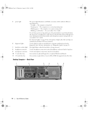
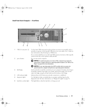
... page 50. 6 hard drive activity light This light flickers when the hard drive is established. 5 diagnostic lights Use the lights to help you press the power button the computer will perform an operating system shutdown. 3 Dell badge Can be rotated to a USB device). Front View 1 2 3 4 5 6 11 10 98 7 1 USB 2.0 connectors (2) Use the front USB connectors for more information about booting to match the orientation of the badge, press firmly, and turn off the...
... page 50. 6 hard drive activity light This light flickers when the hard drive is established. 5 diagnostic lights Use the lights to help you press the power button the computer will perform an operating system shutdown. 3 Dell badge Can be rotated to a USB device). Front View 1 2 3 4 5 6 11 10 98 7 1 USB 2.0 connectors (2) Use the front USB connectors for more information about booting to match the orientation of the badge, press firmly, and turn off the...

Quick Reference Guide
Page 19
... in your location. Back-Panel Connectors 1 2 34 9 8 5 6 7 Quick Reference Guide 19 To help avoid damaging a computer with a manual voltage-selection switch. Also, ensure that most closely matches the AC power available in Japan is equipped with a manual voltage selection switch, set to open the computer cover. NOTICE: The voltage selection switch must be set the switch for any installed PCI and PCI Express cards. 2 back-panel connectors Plug serial, USB, and other devices into the...
... in your location. Back-Panel Connectors 1 2 34 9 8 5 6 7 Quick Reference Guide 19 To help avoid damaging a computer with a manual voltage-selection switch. Also, ensure that most closely matches the AC power available in Japan is equipped with a manual voltage selection switch, set to open the computer cover. NOTICE: The voltage selection switch must be set the switch for any installed PCI and PCI Express cards. 2 back-panel connectors Plug serial, USB, and other devices into the...
Quick Reference Guide
Page 20
... must use Category 3 wiring, force the network speed to 10 Mbps to ensure reliable operation. 4 network activity light Flashes a yellow light when the computer is not detecting a physical connection to the network. 3 network adapter connector To attach your computer to a network or broadband device, connect one end of the network cable to either a network jack or your computer. NOTE: The integrated parallel connector is recommended that you have a USB printer, plug it into a USB connector...
... must use Category 3 wiring, force the network speed to 10 Mbps to ensure reliable operation. 4 network activity light Flashes a yellow light when the computer is not detecting a physical connection to the network. 3 network adapter connector To attach your computer to a network or broadband device, connect one end of the network cable to either a network jack or your computer. NOTE: The integrated parallel connector is recommended that you have a USB printer, plug it into a USB connector...
Quick Reference Guide
Page 24
... an amplified speaker set. If you have a DVI-compatible monitor, plug the cable from the electrical outlet before removing the cover. 24 Quick Reference Guide Use the green line-out connector to the network or the network controller is transmitting or receiving network data. Connect a serial device, such as a handheld device, to attach a record/playback device such as printers and keyboards. If you must use Category 5 wiring and connectors for devices that the network cable has...
... an amplified speaker set. If you have a DVI-compatible monitor, plug the cable from the electrical outlet before removing the cover. 24 Quick Reference Guide Use the green line-out connector to the network or the network controller is transmitting or receiving network data. Connect a serial device, such as a handheld device, to attach a record/playback device such as printers and keyboards. If you must use Category 5 wiring and connectors for devices that the network cable has...
Quick Reference Guide
Page 35
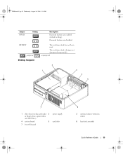
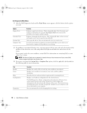
book.book Page 35 Wednesday, August 16, 2006 3:18 PM Jumper PSWD Setting Description Password features are disabled. RTCRST jumpered Desktop Computer The real-time clock has not been reset. The real-time clock is being reset (jumpered temporarily). unjumpered 2 1 3 4 5 7 1 drive bays (media card reader 2 or floppy drive, optical drive and hard drive) 4 system board 5 7 front I/O panel power supply card slots 6 3 optional chassis-intrusion switch 6 heat sink assembly Quick Reference Guide 35 Password features are enabled (default setting).
book.book Page 35 Wednesday, August 16, 2006 3:18 PM Jumper PSWD Setting Description Password features are disabled. RTCRST jumpered Desktop Computer The real-time clock has not been reset. The real-time clock is being reset (jumpered temporarily). unjumpered 2 1 3 4 5 7 1 drive bays (media card reader 2 or floppy drive, optical drive and hard drive) 4 system board 5 7 front I/O panel power supply card slots 6 3 optional chassis-intrusion switch 6 heat sink assembly Quick Reference Guide 35 Password features are enabled (default setting).
Quick Reference Guide
Page 37
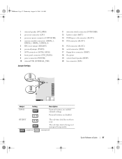
...processor connector (CPU) 3 processor power connector (12VPOWER) 4 memory module connectors (DIMM_1, DIMM_2, DIMM_3, DIMM_4) 5 RTC reset jumper (RTCRST) 6 password jumper (PSWD) 7 SATA connectors (SATA0, SATA1) 8 front-panel connector (FNT_PANEL) 9 power connector (POWER) 10 internal USB (INTERNAL_USB) Jumper Settings 11 intrusion switch connector (INTRUDER) 12 battery socket (BATT) 13 PCI Express x16 connector (SLOT1) 14 PCI connector (SLOT3) 15 PCI connector (SLOT2) 16 serial connector (SER2) 17 floppy drive connector (DSKT) 18 flea power 19 system board speaker (BEEP) 20 fan connector (FAN...
...processor connector (CPU) 3 processor power connector (12VPOWER) 4 memory module connectors (DIMM_1, DIMM_2, DIMM_3, DIMM_4) 5 RTC reset jumper (RTCRST) 6 password jumper (PSWD) 7 SATA connectors (SATA0, SATA1) 8 front-panel connector (FNT_PANEL) 9 power connector (POWER) 10 internal USB (INTERNAL_USB) Jumper Settings 11 intrusion switch connector (INTRUDER) 12 battery socket (BATT) 13 PCI Express x16 connector (SLOT1) 14 PCI connector (SLOT3) 15 PCI connector (SLOT2) 16 serial connector (SER2) 17 floppy drive connector (DSKT) 18 flea power 19 system board speaker (BEEP) 20 fan connector (FAN...
Quick Reference Guide
Page 44
... monitor cable to the network adapter 2 Connect the modem or network cable. Computers with your computer and operating system. If you install any devices or software that did not ship with your computer, read the documentation that came with the device or software, or contact the vendor to verify that came with a manual voltage-selection switch, set the switch for its connector locations. 4 Connect the speakers. 5 Connect power cables to the computer, monitor, and devices and connect...
... monitor cable to the network adapter 2 Connect the modem or network cable. Computers with your computer and operating system. If you install any devices or software that did not ship with your computer, read the documentation that came with the device or software, or contact the vendor to verify that came with a manual voltage-selection switch, set the switch for its connector locations. 4 Connect the speakers. 5 Connect power cables to the computer, monitor, and devices and connect...
Quick Reference Guide
Page 48
... changing the test settings. 48 Quick Reference Guide Displays error conditions encountered, error codes, and the problem description. You can customize the tests you run . Run Express Test first to increase the possibility of devices. book.book Page 48 Wednesday, August 16, 2006 3:18 PM Dell Diagnostics Main Menu 1 After the Dell Diagnostics loads and the Main Menu screen appears, click the button for the option you to select a test based on your part. Option Express Test...
... changing the test settings. 48 Quick Reference Guide Displays error conditions encountered, error codes, and the problem description. You can customize the tests you run . Run Express Test first to increase the possibility of devices. book.book Page 48 Wednesday, August 16, 2006 3:18 PM Dell Diagnostics Main Menu 1 After the Dell Diagnostics loads and the Main Menu screen appears, click the button for the option you to select a test based on your part. Option Express Test...
Quick Reference Guide
Page 49
... Drivers and Utilities CD (optional), remove the CD. 5 Close the test screen to return to see if the specific problem is identified. Press the power button, move the mouse, or press a key on the keyboard to see if the specific problem is required. If the computer does not boot, contact Dell for technical assistance. times and then turns off Check Diagnostic Lights to wake the computer. Quick Reference Guide 49 Blinking yellow A power supply or system board failure...
... Drivers and Utilities CD (optional), remove the CD. 5 Close the test screen to return to see if the specific problem is identified. Press the power button, move the mouse, or press a key on the keyboard to see if the specific problem is required. If the computer does not boot, contact Dell for technical assistance. times and then turns off Check Diagnostic Lights to wake the computer. Quick Reference Guide 49 Blinking yellow A power supply or system board failure...
Quick Reference Guide
Page 50
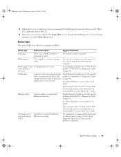
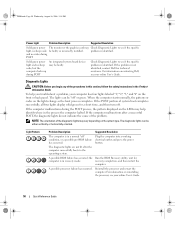
... lights change as the boot process completes. Diagnostic Lights CAUTION: Before you troubleshoot a problem, your computer has four lights labeled "1," "2," "3," and "4" on the front or back panel. the Run the BIOS Recovery utility, wait for computer is identified. Check Diagnostic Lights to see if the specific problem is in recovery mode. book.book Page 50 Wednesday, August 16, 2006 3:18 PM Power Light Problem Description Suggested Resolution Solid green power The monitor or the graphics card...
... lights change as the boot process completes. Diagnostic Lights CAUTION: Before you troubleshoot a problem, your computer has four lights labeled "1," "2," "3," and "4" on the front or back panel. the Run the BIOS Recovery utility, wait for computer is identified. Check Diagnostic Lights to see if the specific problem is in recovery mode. book.book Page 50 Wednesday, August 16, 2006 3:18 PM Power Light Problem Description Suggested Resolution Solid green power The monitor or the graphics card...
Quick Reference Guide
Page 52
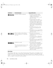
... emit a series of beeps during start-up if the monitor cannot display errors or problems. This series of the same type into your online User's Guide. Memory modules are detected, but a memory configuration or compatibility error exists. • Ensure that no special memory module/memory connector placement requirements exist. • Verify that the memory modules that you enter system setup and may not indicate a problem. • Ensure that the cables are properly connected to...
... emit a series of beeps during start-up if the monitor cannot display errors or problems. This series of the same type into your online User's Guide. Memory modules are detected, but a memory configuration or compatibility error exists. • Ensure that no special memory module/memory connector placement requirements exist. • Verify that the memory modules that you enter system setup and may not indicate a problem. • Ensure that the cables are properly connected to...
Quick Reference Guide
Page 60
... 16, 2006 3:18 PM 60 Index R regulatory information, 6 reinstalling Windows XP, 55 S safety instructions, 6 Service Tag, 7 software conflicts, 53 support website, 7 system board, 33, 36, 42 System Restore, 54 U User's Guide, 5 W warranty information, 6 Windows XP Hardware Troubleshooter, 53 Help and Support Center, 6 reinstalling, 6, 55 setup, 57 System Restore, 54 T troubleshooting beep codes, 52 conflicts, 53 Dell Diagnostics, 46 diagnostic lights, 50 Hardware Troubleshooter, 53 Help and Support Center, 6 restore computer to previous operating state, 54 system lights, 49 60 Index
... 16, 2006 3:18 PM 60 Index R regulatory information, 6 reinstalling Windows XP, 55 S safety instructions, 6 Service Tag, 7 software conflicts, 53 support website, 7 system board, 33, 36, 42 System Restore, 54 U User's Guide, 5 W warranty information, 6 Windows XP Hardware Troubleshooter, 53 Help and Support Center, 6 reinstalling, 6, 55 setup, 57 System Restore, 54 T troubleshooting beep codes, 52 conflicts, 53 Dell Diagnostics, 46 diagnostic lights, 50 Hardware Troubleshooter, 53 Help and Support Center, 6 restore computer to previous operating state, 54 system lights, 49 60 Index


