Quick Reference Guide
Page 7
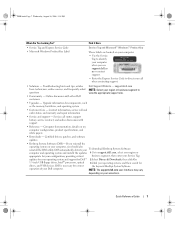
... configuration, providing critical business segment, then enter your operating system, and then search for Dell™ 2 Select Drivers & Downloads, then click Go. 3.5-inch USB floppy drives, Intel® processors, optical 3 Click your Service Tag. NOTE: The support.dell.com user interface may vary depending on my computer configuration, product specifications, and white papers...
... configuration, providing critical business segment, then enter your operating system, and then search for Dell™ 2 Select Drivers & Downloads, then click Go. 3.5-inch USB floppy drives, Intel® processors, optical 3 Click your Service Tag. NOTE: The support.dell.com user interface may vary depending on my computer configuration, product specifications, and white papers...
Quick Reference Guide
Page 25
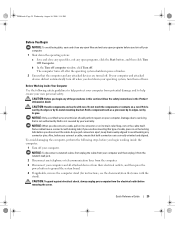
...system, turn off when you begin any of the procedures in this type of cable, press in the Product Information Guide. Hold a component such as a processor by its edges, not by your computer. if you disconnect a cable, pull on its connector or on the cable itself. NOTICE: To disconnect a ...them evenly aligned to ground the system board. 4 If applicable, remove the computer stand (for instructions, see the documentation that is not authorized by Dell is not covered by its pins. If your own personal safety. b In the Turn off computer window, click Turn off . As you disconnect the...
...system, turn off when you begin any of the procedures in this type of cable, press in the Product Information Guide. Hold a component such as a processor by its edges, not by your computer. if you disconnect a cable, pull on its connector or on the cable itself. NOTICE: To disconnect a ...them evenly aligned to ground the system board. 4 If applicable, remove the computer stand (for instructions, see the documentation that is not authorized by Dell is not covered by its pins. If your own personal safety. b In the Turn off computer window, click Turn off . As you disconnect the...
Quick Reference Guide
Page 34
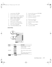
book.book Page 34 Wednesday, August 16, 2006 3:18 PM 1 fan connector (FAN) 12 battery socket (BATT) 2 processor connector (CPU) 13 PCI Express x16 connector (SLOT1) 3 processor power connector (12VPOWER) 14 PCI Express x1 connector (SLOT4) 4 memory module connectors (DIMM_1, DIMM_2, DIMM_3, DIMM_4) 15 PCI connector (SLOT2) 5 RTC reset jumper (RTCRST) 16 ...
book.book Page 34 Wednesday, August 16, 2006 3:18 PM 1 fan connector (FAN) 12 battery socket (BATT) 2 processor connector (CPU) 13 PCI Express x16 connector (SLOT1) 3 processor power connector (12VPOWER) 14 PCI Express x1 connector (SLOT4) 4 memory module connectors (DIMM_1, DIMM_2, DIMM_3, DIMM_4) 15 PCI connector (SLOT2) 5 RTC reset jumper (RTCRST) 16 ...
Quick Reference Guide
Page 37
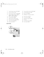
... setting). RTCRST jumpered The real-time clock has not been reset. book.book Page 37 Wednesday, August 16, 2006 3:18 PM 1 internal speaker (INT_SPKR) 2 processor connector (CPU) 3 processor power connector (12VPOWER) 4 memory module connectors (DIMM_1, DIMM_2, DIMM_3, DIMM_4) 5 RTC reset jumper (RTCRST) 6 password jumper (PSWD) 7 SATA connectors (SATA0, SATA1) 8 front-panel connector...
... setting). RTCRST jumpered The real-time clock has not been reset. book.book Page 37 Wednesday, August 16, 2006 3:18 PM 1 internal speaker (INT_SPKR) 2 processor connector (CPU) 3 processor power connector (12VPOWER) 4 memory module connectors (DIMM_1, DIMM_2, DIMM_3, DIMM_4) 5 RTC reset jumper (RTCRST) 6 password jumper (PSWD) 7 SATA connectors (SATA0, SATA1) 8 front-panel connector...
Quick Reference Guide
Page 40
book.book Page 40 Wednesday, August 16, 2006 3:18 PM 1 internal speaker connector (INT_SPKR) 2 processor connector (CPU) 3 processor power connector (12VPOWER) 4 memory module connectors (DIMM_1, DIMM_2, DIMM_3, DIMM_4) 5 RTC reset jumper (RTCRST) 6 password jumper (PSWD) 7 SATA connectors (SATA0, SATA1) 8 front-panel connector (FNT_PANEL) 9 ...
book.book Page 40 Wednesday, August 16, 2006 3:18 PM 1 internal speaker connector (INT_SPKR) 2 processor connector (CPU) 3 processor power connector (12VPOWER) 4 memory module connectors (DIMM_1, DIMM_2, DIMM_3, DIMM_4) 5 RTC reset jumper (RTCRST) 6 password jumper (PSWD) 7 SATA connectors (SATA0, SATA1) 8 front-panel connector (FNT_PANEL) 9 ...
Quick Reference Guide
Page 42
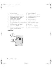
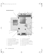
book.book Page 42 Wednesday, August 16, 2006 3:18 PM System Board Components 1 2 3 4 5 6 14 7 8 13 12 9 11 10 1 fan connector (FAN_FRONT) 2 internal speaker connector (INT_SPKR) 3 system board speaker (BEEP) 4 channel B memory connector (DIMM_2) 5 channel A memory connector (DIMM_1) 6 SATA data cable connector(SATA0) 7 battery (BATT) 8 clear CMOS jumper (RTCRST) 9 password jumper (PSWD) 10 hard-drive fan connector (FAN_HDD) 11 hard-drive power connector (SATA_PWR) 12 fan connector (FAN_REAR) 13 intrusion switch connector (INTRUDER) 14 processor (CPU) 42 Quick Reference Guide
book.book Page 42 Wednesday, August 16, 2006 3:18 PM System Board Components 1 2 3 4 5 6 14 7 8 13 12 9 11 10 1 fan connector (FAN_FRONT) 2 internal speaker connector (INT_SPKR) 3 system board speaker (BEEP) 4 channel B memory connector (DIMM_2) 5 channel A memory connector (DIMM_1) 6 SATA data cable connector(SATA0) 7 battery (BATT) 8 clear CMOS jumper (RTCRST) 9 password jumper (PSWD) 10 hard-drive fan connector (FAN_HDD) 11 hard-drive power connector (SATA_PWR) 12 fan connector (FAN_REAR) 13 intrusion switch connector (INTRUDER) 14 processor (CPU) 42 Quick Reference Guide
Quick Reference Guide
Page 50
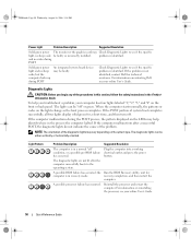
...you begin any of the problem. The diagnostic lights can be either vertically or horizontally oriented. problem is not identified, contact Dell for computer is identified. To help identify where in a normal "off" condition, or a possible pre-BIOS failure has occurred... computer. Diagnostic Lights CAUTION: Before you troubleshoot a problem, your computer has four lights labeled "1," "2," "3," and "4" on reinstalling the processor, see if the specific problem is in the Product Information Guide. When the computer starts normally, the patterns or codes on the system ...
...you begin any of the problem. The diagnostic lights can be either vertically or horizontally oriented. problem is not identified, contact Dell for computer is identified. To help identify where in a normal "off" condition, or a possible pre-BIOS failure has occurred... computer. Diagnostic Lights CAUTION: Before you troubleshoot a problem, your computer has four lights labeled "1," "2," "3," and "4" on reinstalling the processor, see if the specific problem is in the Product Information Guide. When the computer starts normally, the patterns or codes on the system ...


