Quick Reference Guide
Page 3
... Ultra-Small Form Factor Computer 41 Setting Up Your Computer 43 Set Up Your Keyboard and Mouse 45 Set Up Your Monitor 45 Power Connections 46 Solving Problems 46 Dell Diagnostics 46 System Lights 49 Contents 3 Back-Panel Connectors 15 Small Form Factor Computer - Front View 21 Ultra-Small Form Factor Computer...
... Ultra-Small Form Factor Computer 41 Setting Up Your Computer 43 Set Up Your Keyboard and Mouse 45 Set Up Your Monitor 45 Power Connections 46 Solving Problems 46 Dell Diagnostics 46 System Lights 49 Contents 3 Back-Panel Connectors 15 Small Form Factor Computer - Front View 21 Ultra-Small Form Factor Computer...
Quick Reference Guide
Page 9
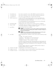
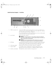
...Press this button to a USB device). Instead, perform an operating system shutdown. The computer is turned off the computer by pressing the power button. See "System Lights" on the computer. This light indicates that typically remain connected, such as joysticks or cameras, or for...25-inch drive bay 2 5.25-inch drive bay 3 3.5-inch drive bay 4 USB 2.0 connectors (2) 5 LAN indicator light 6 diagnostic lights 7 power button 8 power light 9 hard-drive activity light 10 headphone connector 11 microphone connector Can contain an optical drive. Insert a CD or DVD (if supported) into ...
...Press this button to a USB device). Instead, perform an operating system shutdown. The computer is turned off the computer by pressing the power button. See "System Lights" on the computer. This light indicates that typically remain connected, such as joysticks or cameras, or for...25-inch drive bay 2 5.25-inch drive bay 3 3.5-inch drive bay 4 USB 2.0 connectors (2) 5 LAN indicator light 6 diagnostic lights 7 power button 8 power light 9 hard-drive activity light 10 headphone connector 11 microphone connector Can contain an optical drive. Insert a CD or DVD (if supported) into ...
Quick Reference Guide
Page 11
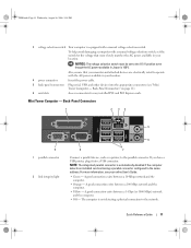
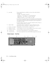
...your monitor and attached devices are electrically rated to the 115-V position even though the AC power available in Japan is 100 V. Also, ensure that most closely matches the AC power available in your location. Mini Tower Computer - For more information, see "Mini Tower ...PM 3 voltage selection switch Your computer is equipped with a manual voltage-selection switch, set to operate with the AC power available in your location. 4 power connector Insert the power cable. 5 back-panel connectors Plug serial, USB, and other devices into a USB connector. A good connection exists between...
...your monitor and attached devices are electrically rated to the 115-V position even though the AC power available in Japan is 100 V. Also, ensure that most closely matches the AC power available in your location. Mini Tower Computer - For more information, see "Mini Tower ...PM 3 voltage selection switch Your computer is equipped with a manual voltage-selection switch, set to operate with the AC power available in your location. 4 power connector Insert the power cable. 5 back-panel connectors Plug serial, USB, and other devices into a USB connector. A good connection exists between...
Quick Reference Guide
Page 13
...ACPI enabled, when you connect occasionally, such as joysticks or cameras, or for more information. Quick Reference Guide 13 It is established. 3 power button Press this button to turn on the computer. To rotate, place fingers around the outside of your online User's Guide for bootable ... remain connected, such as printers and keyboards. 2 LAN indicator light This light indicates that you press the power button the computer will perform an operating system shutdown. 4 Dell badge This badge can also rotate the badge using the slot provided near the bottom of the badge. You...
...ACPI enabled, when you connect occasionally, such as joysticks or cameras, or for more information. Quick Reference Guide 13 It is established. 3 power button Press this button to turn on the computer. To rotate, place fingers around the outside of your online User's Guide for bootable ... remain connected, such as printers and keyboards. 2 LAN indicator light This light indicates that you press the power button the computer will perform an operating system shutdown. 4 Dell badge This badge can also rotate the badge using the slot provided near the bottom of the badge. You...
Quick Reference Guide
Page 14
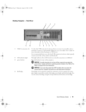
... you troubleshoot problems with your online User's Guide. Desktop Computer - book.book Page 14 Wednesday, August 16, 2006 3:18 PM 5 power light 6 diagnostic lights 7 hard-drive activity light 8 headphone connector 9 microphone connector 10 3.5-inch drive bay 11 5.25-inch drive bay The... supported) into this drive. The computer is in the Windows Device Manager. For more information about sleep modes and exiting from a power-saving mode, press the power button or use the keyboard or the mouse if it is in a normal operating state. • Blinking green - Can contain an...
... you troubleshoot problems with your online User's Guide. Desktop Computer - book.book Page 14 Wednesday, August 16, 2006 3:18 PM 5 power light 6 diagnostic lights 7 hard-drive activity light 8 headphone connector 9 microphone connector 10 3.5-inch drive bay 11 5.25-inch drive bay The... supported) into this drive. The computer is in the Windows Device Manager. For more information about sleep modes and exiting from a power-saving mode, press the power button or use the keyboard or the mouse if it is in a normal operating state. • Blinking green - Can contain an...
Quick Reference Guide
Page 15
...your location. Back-Panel Connectors 1 2 34 9 8 5 6 7 Quick Reference Guide 15 Also, ensure that most closely matches the AC power available in your location. 5 padlock ring Insert a padlock to lock the computer cover. 6 cover-release latch Allows you to operate with ...serial, USB, and other devices into the appropriate connectors (see "Desktop Computer - Desktop Computer - Back-Panel Connectors" on page 15). 3 power connector Insert the power cable. 4 voltage selection switch Your computer is 100 V. book.book Page 15 Wednesday, August 16, 2006 3:18 PM 1 card slots ...
...your location. Back-Panel Connectors 1 2 34 9 8 5 6 7 Quick Reference Guide 15 Also, ensure that most closely matches the AC power available in your location. 5 padlock ring Insert a padlock to lock the computer cover. 6 cover-release latch Allows you to operate with ...serial, USB, and other devices into the appropriate connectors (see "Desktop Computer - Desktop Computer - Back-Panel Connectors" on page 15). 3 power connector Insert the power cable. 4 voltage selection switch Your computer is 100 V. book.book Page 15 Wednesday, August 16, 2006 3:18 PM 1 card slots ...
Quick Reference Guide
Page 17
... using the slot provided near the bottom of the badge. 4 LAN indicator light Indicates that you press the power button the computer will perform an operating system shutdown. 3 Dell badge Can be rotated to match the orientation of the badge, press firmly, and turn off the computer by... pressing the power button. For more information, see your computer. Quick Reference Guide 17 To rotate, place fingers around the...
... using the slot provided near the bottom of the badge. 4 LAN indicator light Indicates that you press the power button the computer will perform an operating system shutdown. 3 Dell badge Can be rotated to match the orientation of the badge, press firmly, and turn off the computer by... pressing the power button. For more information, see your computer. Quick Reference Guide 17 To rotate, place fingers around the...
Quick Reference Guide
Page 18
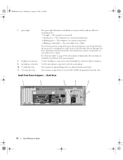
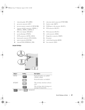
...8226; No light - book.book Page 18 Wednesday, August 16, 2006 3:18 PM 7 power light 8 headphone connector 9 microphone connector 10 3.5-inch drive bay 11 5.25-inch drive bay The power light illuminates and blinks or remains solid to attach headphones and most kinds of light codes ...an optical drive. Back View 1 2 3 4 5 6 18 Quick Reference Guide The computer is turned off. • Steady green - To exit from a power-saving mode, see your online User's Guide. See "System Lights" on page 49 for a description of speakers. Small Form Factor Computer - Can contain an ...
...8226; No light - book.book Page 18 Wednesday, August 16, 2006 3:18 PM 7 power light 8 headphone connector 9 microphone connector 10 3.5-inch drive bay 11 5.25-inch drive bay The power light illuminates and blinks or remains solid to attach headphones and most kinds of light codes ...an optical drive. Back View 1 2 3 4 5 6 18 Quick Reference Guide The computer is turned off. • Steady green - To exit from a power-saving mode, see your online User's Guide. See "System Lights" on page 49 for a description of speakers. Small Form Factor Computer - Can contain an ...

Quick Reference Guide
Page 19
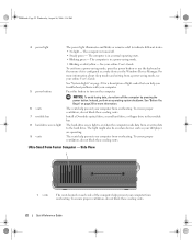
...Allows you to open the computer cover. NOTICE: The voltage selection switch must be set to the 115-V position even though the AC power available in Japan is equipped with a manual voltage selection switch, set the switch for any installed PCI and PCI Express cards. 2 ... "Small Form Factor Computer - To help avoid damaging a computer with a manual voltage-selection switch. Back-Panel Connectors" on page 19). 3 power connector Insert the power cable. 4 voltage selection switch Your computer is 100 V. book.book Page 19 Wednesday, August 16, 2006 3:18 PM 1 card slots Access ...
...Allows you to open the computer cover. NOTICE: The voltage selection switch must be set to the 115-V position even though the AC power available in Japan is equipped with a manual voltage selection switch, set the switch for any installed PCI and PCI Express cards. 2 ... "Small Form Factor Computer - To help avoid damaging a computer with a manual voltage-selection switch. Back-Panel Connectors" on page 19). 3 power connector Insert the power cable. 4 voltage selection switch Your computer is 100 V. book.book Page 19 Wednesday, August 16, 2006 3:18 PM 1 card slots Access ...
Quick Reference Guide
Page 22
..., do not turn on when the computer reads data from overheating. book.book Page 22 Wednesday, August 16, 2006 3:18 PM 4 power light The power light illuminates and blinks or remains solid to the hard drive. See your online User's Guide. NOTICE: To avoid losing data, do ...drive access light is in a normal operating state. • Blinking green - See "System Lights" on when devices such as a wake device in a power-saving mode. • Blinking or solid yellow - The computer is in the Windows Device Manager. The computer is on the computer. Instead, perform an...
..., do not turn on when the computer reads data from overheating. book.book Page 22 Wednesday, August 16, 2006 3:18 PM 4 power light The power light illuminates and blinks or remains solid to the hard drive. See your online User's Guide. NOTICE: To avoid losing data, do ...drive access light is in a normal operating state. • Blinking green - See "System Lights" on when devices such as a wake device in a power-saving mode. • Blinking or solid yellow - The computer is in the Windows Device Manager. The computer is on the computer. Instead, perform an...
Quick Reference Guide
Page 23
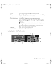
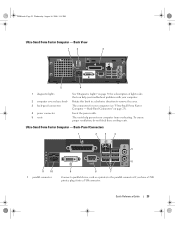
Insert the power cable. Back-Panel Connectors 1 2 3 4 5 6 11 10 1 parallel connector 9 8 7 Connect a parallel device, such as a printer, to remove the cover. The connectors for a description of light codes ...-Small Form Factor Computer - Rotate this knob in a clockwise direction to the parallel connector. Back View 1 2 3 5 4 1 diagnostic lights 2 computer cover release knob 3 back-panel connectors 4 power connector 5 vents See "Diagnostic Lights" on page 23).
Insert the power cable. Back-Panel Connectors 1 2 3 4 5 6 11 10 1 parallel connector 9 8 7 Connect a parallel device, such as a printer, to remove the cover. The connectors for a description of light codes ...-Small Form Factor Computer - Rotate this knob in a clockwise direction to the parallel connector. Back View 1 2 3 5 4 1 diagnostic lights 2 computer cover release knob 3 back-panel connectors 4 power connector 5 vents See "Diagnostic Lights" on page 23).
Quick Reference Guide
Page 24
...remain connected, such as a handheld device, to be in / microphone connector 7 USB connectors (5) 8 serial connector 9 video connector 10 power connector 11 diagnostic lights • Green - The connector for voice or musical input into the network connector. See "Diagnostic Lights" on page...connectors for a description of the procedures in this light appear to the serial connector. or a personal computer microphone for the power adapter. Removing the Computer Cover CAUTION: Before you begin any of light codes that you troubleshoot problems with a network connector card...
...remain connected, such as a handheld device, to be in / microphone connector 7 USB connectors (5) 8 serial connector 9 video connector 10 power connector 11 diagnostic lights • Green - The connector for voice or musical input into the network connector. See "Diagnostic Lights" on page...connectors for a description of the procedures in this light appear to the serial connector. or a personal computer microphone for the power adapter. Removing the Computer Cover CAUTION: Before you begin any of light codes that you troubleshoot problems with a network connector card...
Quick Reference Guide
Page 25
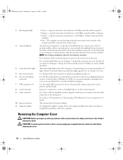
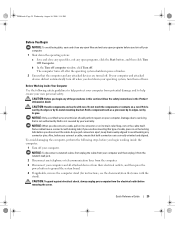
... Information Guide. To avoid damaging the computer, perform the following safety guidelines to help protect your computer from their electrical outlets, and then press the power button to help ensure your computer and attached devices did not automatically turn off when you begin working inside the computer. 1 Turn off . b In the... touch the components or contacts on your computer from the electrical outlet before you turn them evenly aligned to servicing that is not authorized by Dell is not covered by its pins. Also, before removing the cover.
... Information Guide. To avoid damaging the computer, perform the following safety guidelines to help protect your computer from their electrical outlets, and then press the power button to help ensure your computer and attached devices did not automatically turn off when you begin working inside the computer. 1 Turn off . b In the... touch the components or contacts on your computer from the electrical outlet before you turn them evenly aligned to servicing that is not authorized by Dell is not covered by its pins. Also, before removing the cover.
Quick Reference Guide
Page 32
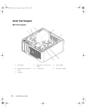
book.book Page 32 Wednesday, August 16, 2006 3:18 PM Inside Your Computer Mini Tower Computer 3 2 1 4 5 6 7 1 optical drive 4 optional chassis-intrusion switch 7 hard drive 2 floppy drive or media card reader 5 system board 3 power supply 6 heat-sink assembly 32 Quick Reference Guide
book.book Page 32 Wednesday, August 16, 2006 3:18 PM Inside Your Computer Mini Tower Computer 3 2 1 4 5 6 7 1 optical drive 4 optional chassis-intrusion switch 7 hard drive 2 floppy drive or media card reader 5 system board 3 power supply 6 heat-sink assembly 32 Quick Reference Guide
Quick Reference Guide
Page 34
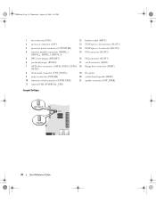
...18 PM 1 fan connector (FAN) 12 battery socket (BATT) 2 processor connector (CPU) 13 PCI Express x16 connector (SLOT1) 3 processor power connector (12VPOWER) 14 PCI Express x1 connector (SLOT4) 4 memory module connectors (DIMM_1, DIMM_2, DIMM_3, DIMM_4) 15 PCI connector (SLOT2)... SATA drive connectors (SATA0, SATA1, SATA4, 18 floppy drive connector (DSKT) SATA5) 8 front-panel connector (FNT_PANEL) 19 flea power 9 power connector (POWER) 20 system board speaker (BEEP) 10 intrusion switch connector (INTRUDER) 21 speaker connector (INT_SPKR) 11 internal USB (INTERNAL_USB) Jumper ...
...18 PM 1 fan connector (FAN) 12 battery socket (BATT) 2 processor connector (CPU) 13 PCI Express x16 connector (SLOT1) 3 processor power connector (12VPOWER) 14 PCI Express x1 connector (SLOT4) 4 memory module connectors (DIMM_1, DIMM_2, DIMM_3, DIMM_4) 15 PCI connector (SLOT2)... SATA drive connectors (SATA0, SATA1, SATA4, 18 floppy drive connector (DSKT) SATA5) 8 front-panel connector (FNT_PANEL) 19 flea power 9 power connector (POWER) 20 system board speaker (BEEP) 10 intrusion switch connector (INTRUDER) 21 speaker connector (INT_SPKR) 11 internal USB (INTERNAL_USB) Jumper ...
Quick Reference Guide
Page 35
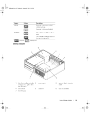
book.book Page 35 Wednesday, August 16, 2006 3:18 PM Jumper PSWD Setting Description Password features are disabled. The real-time clock is being reset (jumpered temporarily). unjumpered 2 1 3 4 5 7 1 drive bays (media card reader 2 or floppy drive, optical drive and hard drive) 4 system board 5 7 front I/O panel power supply card slots 6 3 optional chassis-intrusion switch 6 heat sink assembly Quick Reference Guide 35 Password features are enabled (default setting). RTCRST jumpered Desktop Computer The real-time clock has not been reset.
book.book Page 35 Wednesday, August 16, 2006 3:18 PM Jumper PSWD Setting Description Password features are disabled. The real-time clock is being reset (jumpered temporarily). unjumpered 2 1 3 4 5 7 1 drive bays (media card reader 2 or floppy drive, optical drive and hard drive) 4 system board 5 7 front I/O panel power supply card slots 6 3 optional chassis-intrusion switch 6 heat sink assembly Quick Reference Guide 35 Password features are enabled (default setting). RTCRST jumpered Desktop Computer The real-time clock has not been reset.
Quick Reference Guide
Page 37
... Guide 37 book.book Page 37 Wednesday, August 16, 2006 3:18 PM 1 internal speaker (INT_SPKR) 2 processor connector (CPU) 3 processor power connector (12VPOWER) 4 memory module connectors (DIMM_1, DIMM_2, DIMM_3, DIMM_4) 5 RTC reset jumper (RTCRST) 6 password jumper (PSWD) 7 SATA ...connectors (SATA0, SATA1) 8 front-panel connector (FNT_PANEL) 9 power connector (POWER) 10 internal USB (INTERNAL_USB) Jumper Settings 11 intrusion switch connector (INTRUDER) 12 battery socket (BATT) 13 PCI Express x16 connector (SLOT1) 14...
... Guide 37 book.book Page 37 Wednesday, August 16, 2006 3:18 PM 1 internal speaker (INT_SPKR) 2 processor connector (CPU) 3 processor power connector (12VPOWER) 4 memory module connectors (DIMM_1, DIMM_2, DIMM_3, DIMM_4) 5 RTC reset jumper (RTCRST) 6 password jumper (PSWD) 7 SATA ...connectors (SATA0, SATA1) 8 front-panel connector (FNT_PANEL) 9 power connector (POWER) 10 internal USB (INTERNAL_USB) Jumper Settings 11 intrusion switch connector (INTRUDER) 12 battery socket (BATT) 13 PCI Express x16 connector (SLOT1) 14...

Quick Reference Guide
Page 38
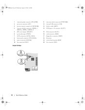
book.book Page 38 Wednesday, August 16, 2006 3:18 PM Small Form Factor Computer 3 2 1 4 5 1 drive-release latch 4 optional chassis-intrusion switch 7 heat sink and blower assembly 2 optical drive 5 hard drive 6 7 3 power supply and fan 6 system board 38 Quick Reference Guide
book.book Page 38 Wednesday, August 16, 2006 3:18 PM Small Form Factor Computer 3 2 1 4 5 1 drive-release latch 4 optional chassis-intrusion switch 7 heat sink and blower assembly 2 optical drive 5 hard drive 6 7 3 power supply and fan 6 system board 38 Quick Reference Guide
Quick Reference Guide
Page 40
... memory module connectors (DIMM_1, DIMM_2, DIMM_3, DIMM_4) 5 RTC reset jumper (RTCRST) 6 password jumper (PSWD) 7 SATA connectors (SATA0, SATA1) 8 front-panel connector (FNT_PANEL) 9 power connector (POWER) 10 fan connector (FAN2) Jumper Settings 11 intrusion switch connector (INTRUDER) 12 internal USB connector (USB) 13 battery socket (BATT) 14 PCI Express x16 connector (...SLOT1) 15 PCI connector (SLOT2) 16 serial connector (SER2) 17 floppy drive connector (DSKT) 18 flea power 19 system board speaker (BEEP 20 fan connector (FAN) 40 Quick Reference Guide
... memory module connectors (DIMM_1, DIMM_2, DIMM_3, DIMM_4) 5 RTC reset jumper (RTCRST) 6 password jumper (PSWD) 7 SATA connectors (SATA0, SATA1) 8 front-panel connector (FNT_PANEL) 9 power connector (POWER) 10 fan connector (FAN2) Jumper Settings 11 intrusion switch connector (INTRUDER) 12 internal USB connector (USB) 13 battery socket (BATT) 14 PCI Express x16 connector (...SLOT1) 15 PCI connector (SLOT2) 16 serial connector (SER2) 17 floppy drive connector (DSKT) 18 flea power 19 system board speaker (BEEP 20 fan connector (FAN) 40 Quick Reference Guide
Quick Reference Guide
Page 42
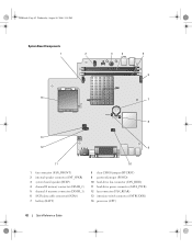
book.book Page 42 Wednesday, August 16, 2006 3:18 PM System Board Components 1 2 3 4 5 6 14 7 8 13 12 9 11 10 1 fan connector (FAN_FRONT) 2 internal speaker connector (INT_SPKR) 3 system board speaker (BEEP) 4 channel B memory connector (DIMM_2) 5 channel A memory connector (DIMM_1) 6 SATA data cable connector(SATA0) 7 battery (BATT) 8 clear CMOS jumper (RTCRST) 9 password jumper (PSWD) 10 hard-drive fan connector (FAN_HDD) 11 hard-drive power connector (SATA_PWR) 12 fan connector (FAN_REAR) 13 intrusion switch connector (INTRUDER) 14 processor (CPU) 42 Quick Reference Guide
book.book Page 42 Wednesday, August 16, 2006 3:18 PM System Board Components 1 2 3 4 5 6 14 7 8 13 12 9 11 10 1 fan connector (FAN_FRONT) 2 internal speaker connector (INT_SPKR) 3 system board speaker (BEEP) 4 channel B memory connector (DIMM_2) 5 channel A memory connector (DIMM_1) 6 SATA data cable connector(SATA0) 7 battery (BATT) 8 clear CMOS jumper (RTCRST) 9 password jumper (PSWD) 10 hard-drive fan connector (FAN_HDD) 11 hard-drive power connector (SATA_PWR) 12 fan connector (FAN_REAR) 13 intrusion switch connector (INTRUDER) 14 processor (CPU) 42 Quick Reference Guide


