Quick Reference Guide
Page 3
... 41 Setting Up Your Computer 43 Set Up Your Keyboard and Mouse 45 Set Up Your Monitor 45 Power Connections 46 Solving Problems 46 Dell Diagnostics 46 System Lights 49 Contents 3 Back-Panel Connectors 15 Small Form Factor Computer - Back View 18 Small Form Factor Computer - Back-Panel Connectors 19 Ultra-Small...
... 41 Setting Up Your Computer 43 Set Up Your Keyboard and Mouse 45 Set Up Your Monitor 45 Power Connections 46 Solving Problems 46 Dell Diagnostics 46 System Lights 49 Contents 3 Back-Panel Connectors 15 Small Form Factor Computer - Back View 18 Small Form Factor Computer - Back-Panel Connectors 19 Ultra-Small...
Quick Reference Guide
Page 4
book.book Page 4 Wednesday, August 16, 2006 3:18 PM Diagnostic Lights 50 Beep Codes 52 Resolving Software and Hardware Incompatibilities 53 Using Microsoft Windows XP System Restore 54 Reinstalling Microsoft Windows XP 55 Using the Drivers and Utilities CD 58 Drivers for Your Computer 58 Index 59 4 Contents
book.book Page 4 Wednesday, August 16, 2006 3:18 PM Diagnostic Lights 50 Beep Codes 52 Resolving Software and Hardware Incompatibilities 53 Using Microsoft Windows XP System Restore 54 Reinstalling Microsoft Windows XP 55 Using the Drivers and Utilities CD 58 Drivers for Your Computer 58 Index 59 4 Contents
Quick Reference Guide
Page 9
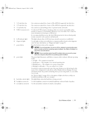
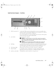
...The computer is turned off the computer by pressing the power button. Use the microphone connector to indicate different operating modes: • No light - book.book Page 9 Wednesday, August 16, 2006 3:18 PM 1 5.25-inch drive bay 2 5.25-inch drive bay 3 3.5-inch ...drive bay 4 USB 2.0 connectors (2) 5 LAN indicator light 6 diagnostic lights 7 power button 8 power light 9 hard-drive activity light 10 headphone connector 11 microphone connector Can contain an optical drive. NOTICE: If your operating system has ACPI enabled, when ...
...The computer is turned off the computer by pressing the power button. Use the microphone connector to indicate different operating modes: • No light - book.book Page 9 Wednesday, August 16, 2006 3:18 PM 1 5.25-inch drive bay 2 5.25-inch drive bay 3 3.5-inch ...drive bay 4 USB 2.0 connectors (2) 5 LAN indicator light 6 diagnostic lights 7 power button 8 power light 9 hard-drive activity light 10 headphone connector 11 microphone connector Can contain an optical drive. NOTICE: If your operating system has ACPI enabled, when ...
Quick Reference Guide
Page 11
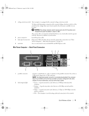
... your location. Mini Tower Computer - A good connection exists between a 10-Mbps network and the computer. • Orange - Back-Panel Connectors 1 2 34 5 9 1 parallel connector 2 link integrity light 6 8 7 Connect a parallel device, such as a printer, to the network. The computer is not detecting a physical connection to the parallel connector. NOTE: The integrated parallel connector...
... your location. Mini Tower Computer - A good connection exists between a 10-Mbps network and the computer. • Orange - Back-Panel Connectors 1 2 34 5 9 1 parallel connector 2 link integrity light 6 8 7 Connect a parallel device, such as a printer, to the network. The computer is not detecting a physical connection to the parallel connector. NOTE: The integrated parallel connector...
Quick Reference Guide
Page 12
... for voice or musical input into the network connector. It is transmitting or receiving network data. If you purchased an optional graphics card, this light appear to the serial port. Connect the other end of the network cable to ensure reliable operation. 4 network activity... light Flashes a yellow light when the computer is recommended that typically remain connected, such as a cassette player, CD player, or VCR.; NOTE: If you must use the y-cable ...
... for voice or musical input into the network connector. It is transmitting or receiving network data. If you purchased an optional graphics card, this light appear to the serial port. Connect the other end of the network cable to ensure reliable operation. 4 network activity... light Flashes a yellow light when the computer is recommended that typically remain connected, such as a cassette player, CD player, or VCR.; NOTE: If you must use the y-cable ...
Quick Reference Guide
Page 13
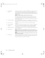
... your operating system has ACPI enabled, when you connect occasionally, such as printers and keyboards. 2 LAN indicator light This light indicates that you press the power button the computer will perform an operating system shutdown. 4 Dell badge This badge can also rotate the badge using the slot provided near the bottom of the...
... your operating system has ACPI enabled, when you connect occasionally, such as printers and keyboards. 2 LAN indicator light This light indicates that you press the power button the computer will perform an operating system shutdown. 4 Dell badge This badge can also rotate the badge using the slot provided near the bottom of the...
Quick Reference Guide
Page 14
... of speakers. Use the headphone connector to attach a microphone. Use the microphone connector to attach headphones and most kinds of light codes that can help you troubleshoot problems with your online User's Guide. Can contain an optional floppy drive or optional Media ... a normal operating state. • Blinking green - Back View 1 2 3 4 5 6 14 Quick Reference Guide Use the lights to indicate different operating states: • No light - The computer is configured as a wake device in a power-saving mode. • Blinking or solid amber - book.book Page...
... of speakers. Use the headphone connector to attach a microphone. Use the microphone connector to attach headphones and most kinds of light codes that can help you troubleshoot problems with your online User's Guide. Can contain an optional floppy drive or optional Media ... a normal operating state. • Blinking green - Back View 1 2 3 4 5 6 14 Quick Reference Guide Use the lights to indicate different operating states: • No light - The computer is configured as a wake device in a power-saving mode. • Blinking or solid amber - book.book Page...
Quick Reference Guide
Page 16
... serial connector 2. Connect your monitor to the serial port. For more information, see your online User's Guide. 2 link integrity light • Green - The computer is transmitting or receiving network data. book.book Page 16 Wednesday, August 16, 2006 3:18 ...automatically disabled if the computer detects an installed card containing a parallel connector configured to ensure reliable operation. 4 network activity light Flashes a yellow light when the computer is not detecting a physical connection to the network. 3 network adapter connector To attach your computer. ...
... serial connector 2. Connect your monitor to the serial port. For more information, see your online User's Guide. 2 link integrity light • Green - The computer is transmitting or receiving network data. book.book Page 16 Wednesday, August 16, 2006 3:18 ...automatically disabled if the computer detects an installed card containing a parallel connector configured to ensure reliable operation. 4 network activity light Flashes a yellow light when the computer is not detecting a physical connection to the network. 3 network adapter connector To attach your computer. ...
Quick Reference Guide
Page 17
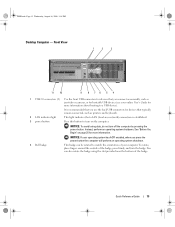
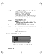
.... See "Before You Begin" on page 25 for devices that you press the power button the computer will perform an operating system shutdown. 3 Dell badge Can be rotated to a USB device). NOTICE: If your computer. To rotate, place fingers around the outside of your operating system has ...or for more information. book.book Page 17 Wednesday, August 16, 2006 3:18 PM Small Form Factor Computer - It is established. 5 diagnostic lights Use the lights to turn off the computer by pressing the power button. NOTICE: To avoid losing data, do not turn on the diagnostic code. Quick Reference...
.... See "Before You Begin" on page 25 for devices that you press the power button the computer will perform an operating system shutdown. 3 Dell badge Can be rotated to a USB device). NOTICE: If your computer. To rotate, place fingers around the outside of your operating system has ...or for more information. book.book Page 17 Wednesday, August 16, 2006 3:18 PM Small Form Factor Computer - It is established. 5 diagnostic lights Use the lights to turn off the computer by pressing the power button. NOTICE: To avoid losing data, do not turn on the diagnostic code. Quick Reference...
Quick Reference Guide
Page 18
... see your online User's Guide. Insert a CD or DVD (if supported) into this drive. Use the headphone connector to attach headphones and most kinds of light codes that can help you troubleshoot problems with your online User's Guide. Back View 1 2 3 4 5 6 18 Quick Reference Guide The computer is turned ... mode, press the power button or use the keyboard or the mouse if it is in the Windows Device Manager. See "System Lights" on page 49 for a description of speakers. Can contain an optical drive. Use the microphone connector to indicate different operating states: •...
... see your online User's Guide. Insert a CD or DVD (if supported) into this drive. Use the headphone connector to attach headphones and most kinds of light codes that can help you troubleshoot problems with your online User's Guide. Back View 1 2 3 4 5 6 18 Quick Reference Guide The computer is turned ... mode, press the power button or use the keyboard or the mouse if it is in the Windows Device Manager. See "System Lights" on page 49 for a description of speakers. Can contain an optical drive. Use the microphone connector to indicate different operating states: •...
Quick Reference Guide
Page 20
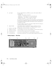
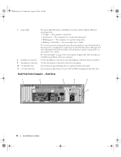
... is automatically disabled if the computer detects an installed card containing a parallel connector configured to ensure reliable operation. 4 network activity light Flashes a yellow light when the computer is transmitting or receiving network data. A good connection exists between a 10-Mbps network and the computer. &#...the other end of the network cable to either a network jack or your network. A high volume of network traffic may make this light appear to be in a steady "on" state. 5 line-out connector Use the green line-out connector (available on computers with ...
... is automatically disabled if the computer detects an installed card containing a parallel connector configured to ensure reliable operation. 4 network activity light Flashes a yellow light when the computer is transmitting or receiving network data. A good connection exists between a 10-Mbps network and the computer. &#...the other end of the network cable to either a network jack or your network. A high volume of network traffic may make this light appear to be in a steady "on" state. 5 line-out connector Use the green line-out connector (available on computers with ...
Quick Reference Guide
Page 22
...floppy drive in the Windows Device Manager. The computer is in a normal operating state. • Blinking green - See "System Lights" on each side of light codes that can help prevent your computer from overheating. To ensure proper ventilation, do not block these cooling vents. To ensure proper..., do not block these cooling vents. 22 Quick Reference Guide book.book Page 22 Wednesday, August 16, 2006 3:18 PM 4 power light The power light illuminates and blinks or remains solid to turn off . • Steady green - See "Before You Begin" on the computer. The ...
...floppy drive in the Windows Device Manager. The computer is in a normal operating state. • Blinking green - See "System Lights" on each side of light codes that can help prevent your computer from overheating. To ensure proper ventilation, do not block these cooling vents. To ensure proper..., do not block these cooling vents. 22 Quick Reference Guide book.book Page 22 Wednesday, August 16, 2006 3:18 PM 4 power light The power light illuminates and blinks or remains solid to turn off . • Steady green - See "Before You Begin" on the computer. The ...
Quick Reference Guide
Page 23
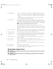
...parallel device, such as a printer, to remove the cover. If you troubleshoot problems with your computer. The connectors for a description of light codes that can help prevent your computer (see "Ultra-Small Form Factor Computer - Back-Panel Connectors" on page 50 for your computer... - Rotate this knob in a clockwise direction to the parallel connector. Back View 1 2 3 5 4 1 diagnostic lights 2 computer cover release knob 3 back-panel connectors 4 power connector 5 vents See "Diagnostic Lights" on page 23). To ensure proper ventilation, do not block these cooling vents.
...parallel device, such as a printer, to remove the cover. If you troubleshoot problems with your computer. The connectors for a description of light codes that can help prevent your computer (see "Ultra-Small Form Factor Computer - Back-Panel Connectors" on page 50 for your computer... - Rotate this knob in a clockwise direction to the parallel connector. Back View 1 2 3 5 4 1 diagnostic lights 2 computer cover release knob 3 back-panel connectors 4 power connector 5 vents See "Diagnostic Lights" on page 23). To ensure proper ventilation, do not block these cooling vents.
Quick Reference Guide
Page 24
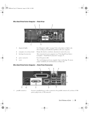
...network controller is turned off in / microphone connector 7 USB connectors (5) 8 serial connector 9 video connector 10 power connector 11 diagnostic lights • Green - It is transmitting or receiving network data. Connect a serial device, such as printers and keyboards. If you ...safety instructions in your computer from your network. book.book Page 24 Wednesday, August 16, 2006 3:18 PM 2 link integrity light 3 network adapter 4 network activity light 5 line-out connector 6 line-in system setup. A good connection exists between a 1000-Mbps (1-Gbps) network and the ...
...network controller is turned off in / microphone connector 7 USB connectors (5) 8 serial connector 9 video connector 10 power connector 11 diagnostic lights • Green - It is transmitting or receiving network data. Connect a serial device, such as printers and keyboards. If you ...safety instructions in your computer from your network. book.book Page 24 Wednesday, August 16, 2006 3:18 PM 2 link integrity light 3 network adapter 4 network activity light 5 line-out connector 6 line-in system setup. A good connection exists between a 1000-Mbps (1-Gbps) network and the ...

Quick Reference Guide
Page 46
...if your computer does not perform as your computer. For information on Dell™ computers. 46 Quick Reference Guide When to help from Dell, write a detailed description of the error, beep codes, or diagnostics light patterns, record your Express Service Code and Service Tag below, and... then contact Dell from the same location as expected. For the latest troubleshooting ...
...if your computer does not perform as your computer. For information on Dell™ computers. 46 Quick Reference Guide When to help from Dell, write a detailed description of the error, beep codes, or diagnostics light patterns, record your Express Service Code and Service Tag below, and... then contact Dell from the same location as expected. For the latest troubleshooting ...
Quick Reference Guide
Page 49
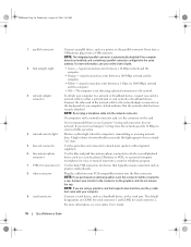
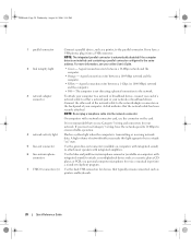
... Blinking yellow A power supply or system board failure has occurred. If the computer does not boot, contact Dell for technical assistance. For information on contacting Dell, see "Diagnostic Lights" on the system board may be set incorrectly. Solid green and a beep code during POST A problem was... "Beep Codes" on diagnosing the beep code see your online User's Guide. Also, check Diagnostic Lights to wake the computer. supply may indicate a computer problem. To exit the Dell Diagnostics and restart the computer, close the Main Menu screen. See "Power Problems" in a power...
... Blinking yellow A power supply or system board failure has occurred. If the computer does not boot, contact Dell for technical assistance. For information on contacting Dell, see "Diagnostic Lights" on the system board may be set incorrectly. Solid green and a beep code during POST A problem was... "Beep Codes" on diagnosing the beep code see your online User's Guide. Also, check Diagnostic Lights to wake the computer. supply may indicate a computer problem. To exit the Dell Diagnostics and restart the computer, close the Main Menu screen. See "Power Problems" in a power...
Quick Reference Guide
Page 50
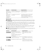
... the front or back panel. For information on contacting Dell, see your computer has four lights labeled "1," "2," "3," and "4" on the LEDs may help you begin any of the diagnostic lights may be faulty. The diagnostic lights can be either vertically or horizontally oriented. A possible ... be faulty or incorrectly installed. If the problem is not identified, contact Dell for computer is in recovery mode. Diagnostic Lights CAUTION: Before you troubleshoot a problem, your online User's Guide. The lights can be "off " condition, or a possible pre-BIOS failure has ...
... the front or back panel. For information on contacting Dell, see your computer has four lights labeled "1," "2," "3," and "4" on the LEDs may help you begin any of the diagnostic lights may be faulty. The diagnostic lights can be either vertically or horizontally oriented. A possible ... be faulty or incorrectly installed. If the problem is not identified, contact Dell for computer is in recovery mode. Diagnostic Lights CAUTION: Before you troubleshoot a problem, your online User's Guide. The lights can be "off " condition, or a possible pre-BIOS failure has ...
Quick Reference Guide
Page 51
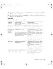
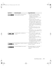
...online User's Guide. For information on reinstalling memory modules, see your computer. • If the problem persists, contact Dell. If the computer starts normally, reinstall an additional module. restart the computer. Continue until you have identified a faulty ...and data cables and occurred. A possible USB failure has occurred. For information on contacting Dell, see your online User's Guide. book.book Page 51 Wednesday, August 16, 2006 3:18 PM Light Pattern Problem Description Suggested Resolution Memory modules are detected, but a memory failure has occurred....
...online User's Guide. For information on reinstalling memory modules, see your computer. • If the problem persists, contact Dell. If the computer starts normally, reinstall an additional module. restart the computer. Continue until you have identified a faulty ...and data cables and occurred. A possible USB failure has occurred. For information on contacting Dell, see your online User's Guide. book.book Page 51 Wednesday, August 16, 2006 3:18 PM Light Pattern Problem Description Suggested Resolution Memory modules are detected, but a memory failure has occurred....
Quick Reference Guide
Page 52
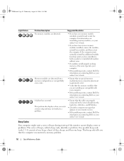
... For information on reinstalling memory modules, see your computer. • If the problem persists, contact Dell. book.book Page 52 Wednesday, August 16, 2006 3:18 PM Light Pattern Problem Description Suggested Resolution No memory modules are detected. • If you have one beep.... For information on contacting Dell, see your computer. • If the problem persists, contact Dell. If the computer starts normally, reinstall...
... For information on reinstalling memory modules, see your computer. • If the problem persists, contact Dell. book.book Page 52 Wednesday, August 16, 2006 3:18 PM Light Pattern Problem Description Suggested Resolution No memory modules are detected. • If you have one beep.... For information on contacting Dell, see your computer. • If the problem persists, contact Dell. If the computer starts normally, reinstall...
Quick Reference Guide
Page 59
..., 6 drivers list of, 58 Drivers and Utilities CD, 5 E End User License Agreement, 6 ergonomics information, 6 error messages beep codes, 52 diagnostic lights, 50 system lights, 49 H hardware beep codes, 52 conflicts, 53 Dell Diagnostics, 46 Hardware Troubleshooter, 53 Help and Support Center, 6 help file Windows Help and Support Center, 6 I installing parts before you begin...
..., 6 drivers list of, 58 Drivers and Utilities CD, 5 E End User License Agreement, 6 ergonomics information, 6 error messages beep codes, 52 diagnostic lights, 50 system lights, 49 H hardware beep codes, 52 conflicts, 53 Dell Diagnostics, 46 Hardware Troubleshooter, 53 Help and Support Center, 6 help file Windows Help and Support Center, 6 I installing parts before you begin...


