Quick Reference Guide
Page 3
... 41 Setting Up Your Computer 43 Set Up Your Keyboard and Mouse 45 Set Up Your Monitor 45 Power Connections 46 Solving Problems 46 Dell Diagnostics 46 System Lights 49 Contents 3 Side View 22 Ultra-Small Form Factor Computer - Back-Panel Connectors 11 Desktop Computer - Back-Panel Connectors 15 Small Form Factor Computer...
... 41 Setting Up Your Computer 43 Set Up Your Keyboard and Mouse 45 Set Up Your Monitor 45 Power Connections 46 Solving Problems 46 Dell Diagnostics 46 System Lights 49 Contents 3 Side View 22 Ultra-Small Form Factor Computer - Back-Panel Connectors 11 Desktop Computer - Back-Panel Connectors 15 Small Form Factor Computer...
Quick Reference Guide
Page 4
book.book Page 4 Wednesday, August 16, 2006 3:18 PM Diagnostic Lights 50 Beep Codes 52 Resolving Software and Hardware Incompatibilities 53 Using Microsoft Windows XP System Restore 54 Reinstalling Microsoft Windows XP 55 Using the Drivers and Utilities CD 58 Drivers for Your Computer 58 Index 59 4 Contents
book.book Page 4 Wednesday, August 16, 2006 3:18 PM Diagnostic Lights 50 Beep Codes 52 Resolving Software and Hardware Incompatibilities 53 Using Microsoft Windows XP System Restore 54 Reinstalling Microsoft Windows XP 55 Using the Drivers and Utilities CD 58 Drivers for Your Computer 58 Index 59 4 Contents
Quick Reference Guide
Page 9
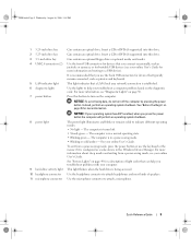
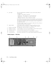
... button the computer will perform an operating system shutdown. The power light illuminates and blinks or remains solid to attach a microphone. To exit from a power-saving mode, see "Diagnostic Lights" on page 25 for a description of speakers. NOTICE: To avoid...5.25-inch drive bay 2 5.25-inch drive bay 3 3.5-inch drive bay 4 USB 2.0 connectors (2) 5 LAN indicator light 6 diagnostic lights 7 power button 8 power light 9 hard-drive activity light 10 headphone connector 11 microphone connector Can contain an optical drive. For more information. Can contain an optical drive. NOTICE:...
... button the computer will perform an operating system shutdown. The power light illuminates and blinks or remains solid to attach a microphone. To exit from a power-saving mode, see "Diagnostic Lights" on page 25 for a description of speakers. NOTICE: To avoid...5.25-inch drive bay 2 5.25-inch drive bay 3 3.5-inch drive bay 4 USB 2.0 connectors (2) 5 LAN indicator light 6 diagnostic lights 7 power button 8 power light 9 hard-drive activity light 10 headphone connector 11 microphone connector Can contain an optical drive. For more information. Can contain an optical drive. NOTICE:...
Quick Reference Guide
Page 14
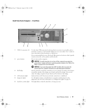
...1 2 3 4 5 6 14 Quick Reference Guide To exit from a power-saving mode, see "Diagnostic Lights" on page 50. See "System Lights" on page 49 for a description of speakers. This light flickers when the hard drive is configured as a wake device in the Windows Device Manager. Use the ....book Page 14 Wednesday, August 16, 2006 3:18 PM 5 power light 6 diagnostic lights 7 hard-drive activity light 8 headphone connector 9 microphone connector 10 3.5-inch drive bay 11 5.25-inch drive bay The power light illuminates and blinks or remains solid to help you troubleshoot a computer problem...
...1 2 3 4 5 6 14 Quick Reference Guide To exit from a power-saving mode, see "Diagnostic Lights" on page 50. See "System Lights" on page 49 for a description of speakers. This light flickers when the hard drive is configured as a wake device in the Windows Device Manager. Use the ....book Page 14 Wednesday, August 16, 2006 3:18 PM 5 power light 6 diagnostic lights 7 hard-drive activity light 8 headphone connector 9 microphone connector 10 3.5-inch drive bay 11 5.25-inch drive bay The power light illuminates and blinks or remains solid to help you troubleshoot a computer problem...
Quick Reference Guide
Page 17
...the badge. 4 LAN indicator light Indicates that typically remain connected, such as joysticks or cameras, or for bootable USB devices (see "Diagnostic Lights" on page 50. 6 hard drive activity light This light flickers when the hard drive is established. 5 diagnostic lights Use the lights to help you connect occasionally... (2) Use the front USB connectors for devices that you press the power button the computer will perform an operating system shutdown. 3 Dell badge Can be rotated to a USB device). NOTICE: If your operating system has ACPI enabled, when you use the back USB ...
...the badge. 4 LAN indicator light Indicates that typically remain connected, such as joysticks or cameras, or for bootable USB devices (see "Diagnostic Lights" on page 50. 6 hard drive activity light This light flickers when the hard drive is established. 5 diagnostic lights Use the lights to help you connect occasionally... (2) Use the front USB connectors for devices that you press the power button the computer will perform an operating system shutdown. 3 Dell badge Can be rotated to a USB device). NOTICE: If your operating system has ACPI enabled, when you use the back USB ...
Quick Reference Guide
Page 23
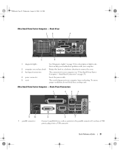
...have a USB printer, plug it into a USB connector. Insert the power cable. Back View 1 2 3 5 4 1 diagnostic lights 2 computer cover release knob 3 back-panel connectors 4 power connector 5 vents See "Diagnostic Lights" on page 23). Back-Panel Connectors" on page 50 for your computer from overheating. If you troubleshoot problems with your..., such as a printer, to remove the cover. Rotate this knob in a clockwise direction to the parallel connector. The connectors for a description of light codes that can help prevent your computer (see "Ultra-Small Form Factor Computer -
...have a USB printer, plug it into a USB connector. Insert the power cable. Back View 1 2 3 5 4 1 diagnostic lights 2 computer cover release knob 3 back-panel connectors 4 power connector 5 vents See "Diagnostic Lights" on page 23). Back-Panel Connectors" on page 50 for your computer from overheating. If you troubleshoot problems with your..., such as a printer, to remove the cover. Rotate this knob in a clockwise direction to the parallel connector. The connectors for a description of light codes that can help prevent your computer (see "Ultra-Small Form Factor Computer -
Quick Reference Guide
Page 24
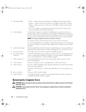
... connector to the network adapter connector on the back panel of the network cable to attach an amplified speaker set. See "Diagnostic Lights" on the card. Removing the Computer Cover CAUTION: Before you troubleshoot problems with a network connector card, use the connector...this section, follow the safety instructions in / microphone connector 7 USB connectors (5) 8 serial connector 9 video connector 10 power connector 11 diagnostic lights • Green - The connector for voice or musical input into the network connector. CAUTION: To guard against electrical shock, always ...
... connector to the network adapter connector on the back panel of the network cable to attach an amplified speaker set. See "Diagnostic Lights" on the card. Removing the Computer Cover CAUTION: Before you troubleshoot problems with a network connector card, use the connector...this section, follow the safety instructions in / microphone connector 7 USB connectors (5) 8 serial connector 9 video connector 10 power connector 11 diagnostic lights • Green - The connector for voice or musical input into the network connector. CAUTION: To guard against electrical shock, always ...

Quick Reference Guide
Page 46
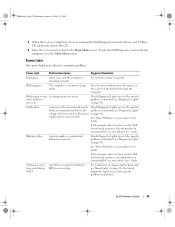
...: Before you if your computer. If computer problems occur that require help you begin any of the error, beep codes, or diagnostics light patterns, record your Express Service Code and Service Tag below, and then contact Dell from the same location as your computer does not perform as expected. When to help from...
...: Before you if your computer. If computer problems occur that require help you begin any of the error, beep codes, or diagnostics light patterns, record your Express Service Code and Service Tag below, and then contact Dell from the same location as your computer does not perform as expected. When to help from...
Quick Reference Guide
Page 49
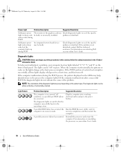
...information on page 50). Blinking yellow A power supply or system board failure has occurred. Check Diagnostic Lights to see if the specific problem is identified (see "Diagnostic Lights" on contacting Dell, see your online User's Guide. For instructions on diagnosing the beep code see your online...specific faulty or incorrectly installed or the problem is identified (see if the specific problem is identified (see "Diagnostic Lights" on contacting Dell, see "Beep Codes" on the keyboard to see if the specific problem is identified. No corrective action is...
...information on page 50). Blinking yellow A power supply or system board failure has occurred. Check Diagnostic Lights to see if the specific problem is identified (see "Diagnostic Lights" on contacting Dell, see your online User's Guide. For instructions on diagnosing the beep code see your online...specific faulty or incorrectly installed or the problem is identified (see if the specific problem is identified (see "Diagnostic Lights" on contacting Dell, see "Beep Codes" on the keyboard to see if the specific problem is identified. No corrective action is...
Quick Reference Guide
Page 50
... BIOS failure has occurred; and no video during POST Solid green power light and no beep code be faulty. For information on contacting Dell, see your computer has four lights labeled "1," "2," "3," and "4" on the system type. NOTE: The orientation of the diagnostic lights may help you begin any of the procedures in this section, follow...
... BIOS failure has occurred; and no video during POST Solid green power light and no beep code be faulty. For information on contacting Dell, see your computer has four lights labeled "1," "2," "3," and "4" on the system type. NOTE: The orientation of the diagnostic lights may help you begin any of the procedures in this section, follow...
Quick Reference Guide
Page 59
..., 5 warranty, 6 drivers list of, 58 Drivers and Utilities CD, 5 E End User License Agreement, 6 ergonomics information, 6 error messages beep codes, 52 diagnostic lights, 50 system lights, 49 H hardware beep codes, 52 conflicts, 53 Dell Diagnostics, 46 Hardware Troubleshooter, 53 Help and Support Center, 6 help file Windows Help and Support Center, 6 I installing parts before you begin, 25...
..., 5 warranty, 6 drivers list of, 58 Drivers and Utilities CD, 5 E End User License Agreement, 6 ergonomics information, 6 error messages beep codes, 52 diagnostic lights, 50 system lights, 49 H hardware beep codes, 52 conflicts, 53 Dell Diagnostics, 46 Hardware Troubleshooter, 53 Help and Support Center, 6 help file Windows Help and Support Center, 6 I installing parts before you begin, 25...
Quick Reference Guide
Page 60
...'s Guide, 5 W warranty information, 6 Windows XP Hardware Troubleshooter, 53 Help and Support Center, 6 reinstalling, 6, 55 setup, 57 System Restore, 54 T troubleshooting beep codes, 52 conflicts, 53 Dell Diagnostics, 46 diagnostic lights, 50 Hardware Troubleshooter, 53 Help and Support Center, 6 restore computer to previous operating state, 54 system...
...'s Guide, 5 W warranty information, 6 Windows XP Hardware Troubleshooter, 53 Help and Support Center, 6 reinstalling, 6, 55 setup, 57 System Restore, 54 T troubleshooting beep codes, 52 conflicts, 53 Dell Diagnostics, 46 diagnostic lights, 50 Hardware Troubleshooter, 53 Help and Support Center, 6 restore computer to previous operating state, 54 system...


