Technical Guide
Page 4
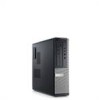
DELL™ OPTIPLEX™ 390 TECHNICAL GUIDEBOOK -FINAL MT System Board Components Number Name 1 Front IO connector (FRONTPANEL)) 2 Internal Speaker Connector (INT_SPKR) 3 System fan Connector (FAN_SYS1) 4 SATA 1 Connector(SATA1) 5 SATA 0 Connector(SATA0) 6 SATA 2 Connector(SATA2) 7 SATA 3 Connector(SATA3) 8 Internal ... 17 18 19 20 21 22 23 24 25 Name PCI-e 16x Connector (SLOT1) System fan Connector (FAN_SYS2) P2 Power Connector(ATX12V) CPU Socket Connector (U27CPU) CPU fan Connector (FAN_CPU) Memory Connector(DIMM1) P1 power Connector (ATX) Power Switch Connector (PWRSW1)...
DELL™ OPTIPLEX™ 390 TECHNICAL GUIDEBOOK -FINAL MT System Board Components Number Name 1 Front IO connector (FRONTPANEL)) 2 Internal Speaker Connector (INT_SPKR) 3 System fan Connector (FAN_SYS1) 4 SATA 1 Connector(SATA1) 5 SATA 0 Connector(SATA0) 6 SATA 2 Connector(SATA2) 7 SATA 3 Connector(SATA3) 8 Internal ... 17 18 19 20 21 22 23 24 25 Name PCI-e 16x Connector (SLOT1) System fan Connector (FAN_SYS2) P2 Power Connector(ATX12V) CPU Socket Connector (U27CPU) CPU fan Connector (FAN_CPU) Memory Connector(DIMM1) P1 power Connector (ATX) Power Switch Connector (PWRSW1)...
Technical Guide
Page 6
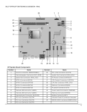
DELL™ OPTIPLEX™ 390 TECHNICAL GUIDEBOOK -FINAL DT System Board Components Number Name 1 Front IO connector (FRONTPANEL)) 2 Internal Speaker Connector (INT_SPKR) 3 System fan Connector (FAN_SYS1) 4 SATA 1 Connector(SATA1) 5 SATA 0 Connector(SATA0) 6 SATA 2 Connector(SATA2) 7 SATA 3 Connector(SATA3) 8 Internal ... 17 18 19 20 21 22 23 24 25 Name PCI-e 16x Connector (SLOT1) System fan Connector (FAN_SYS2) P2 Power Connector(ATX12V) CPU Socket Connector (U27CPU) CPU fan Connector (FAN_CPU) Memory Connector(DIMM1) P1 power Connector (ATX) Power Switch Connector (PWRSW1)...
DELL™ OPTIPLEX™ 390 TECHNICAL GUIDEBOOK -FINAL DT System Board Components Number Name 1 Front IO connector (FRONTPANEL)) 2 Internal Speaker Connector (INT_SPKR) 3 System fan Connector (FAN_SYS1) 4 SATA 1 Connector(SATA1) 5 SATA 0 Connector(SATA0) 6 SATA 2 Connector(SATA2) 7 SATA 3 Connector(SATA3) 8 Internal ... 17 18 19 20 21 22 23 24 25 Name PCI-e 16x Connector (SLOT1) System fan Connector (FAN_SYS2) P2 Power Connector(ATX12V) CPU Socket Connector (U27CPU) CPU fan Connector (FAN_CPU) Memory Connector(DIMM1) P1 power Connector (ATX) Power Switch Connector (PWRSW1)...
Technical Guide
Page 18
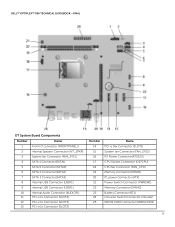
... (APFC) power supply. If you have questions, please contact the manufacture to confirm the output type. Dell recommends only Universal Power Supplies (UPS) based on PSU max wattage) Power Supply Fan Compliance: 1watt requirement Blue Angel Compliant Climate Savers / 80Plus Compliant FEMP (CECP) Standby Power Compliant 4.0A... Yes Yes Yes No Yes No Yes Yes Yes 4.0A 0.5A 235W 60W N/A 819 BTU 60*25mm Yes Yes Yes Yes 18 DELL™ OPTIPLEX™ 390 TECHNICAL GUIDEBOOK -FINAL POWER NOTE: These form factors utilize a more than one 12v rail) BTUs/h (based on Sine Wave output for...
... (APFC) power supply. If you have questions, please contact the manufacture to confirm the output type. Dell recommends only Universal Power Supplies (UPS) based on PSU max wattage) Power Supply Fan Compliance: 1watt requirement Blue Angel Compliant Climate Savers / 80Plus Compliant FEMP (CECP) Standby Power Compliant 4.0A... Yes Yes Yes No Yes No Yes Yes Yes 4.0A 0.5A 235W 60W N/A 819 BTU 60*25mm Yes Yes Yes Yes 18 DELL™ OPTIPLEX™ 390 TECHNICAL GUIDEBOOK -FINAL POWER NOTE: These form factors utilize a more than one 12v rail) BTUs/h (based on Sine Wave output for...
Technical Guide
Page 34
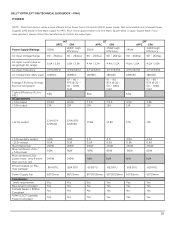
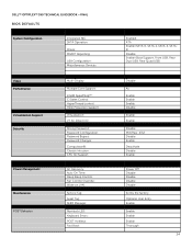
DELL™ OPTIPLEX™ 390 TECHNICAL GUIDEBOOK -FINAL BIOS DEFAULTS System Configuration Integrated NIC: SATA Operation: Drives: SMART Reporting: USB Configuration: Miscellaneous Devices: Video Performance Virtualization Support Security ... Direct I/O: Strong Password: Password Configuration: Password Bypass: Password Changes: Computrace®: Chassis Intrusion: CPU XD Support: AC Recovery: Auto On Time: Deep Sleep Control: Fan Control Override: Wake on LAN: Service Tag: Asset Tag: SERR Message: Numlock LED: Keyboard Errors: POST HotKeys: Fast Boot: Enabled ATA Enable (SATA-0, SATA-1,...
DELL™ OPTIPLEX™ 390 TECHNICAL GUIDEBOOK -FINAL BIOS DEFAULTS System Configuration Integrated NIC: SATA Operation: Drives: SMART Reporting: USB Configuration: Miscellaneous Devices: Video Performance Virtualization Support Security ... Direct I/O: Strong Password: Password Configuration: Password Bypass: Password Changes: Computrace®: Chassis Intrusion: CPU XD Support: AC Recovery: Auto On Time: Deep Sleep Control: Fan Control Override: Wake on LAN: Service Tag: Asset Tag: SERR Message: Numlock LED: Keyboard Errors: POST HotKeys: Fast Boot: Enabled ATA Enable (SATA-0, SATA-1,...
Owners Manual
Page 4
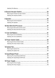
... Battery 32 12 Power Switch Cable 33 Removing the Power-Switch Cable 33 Installing The Power Switch Cable 34 13 System Fan 35 Removing the System Fan 35 Installing The System Fan 36 14 Input/Output Panel 37 Removing The Input/Output (I/O) Panel 37 Installing The Input/Output (I/O) Panel 39 15 Power Supply...
... Battery 32 12 Power Switch Cable 33 Removing the Power-Switch Cable 33 Installing The Power Switch Cable 34 13 System Fan 35 Removing the System Fan 35 Installing The System Fan 36 14 Input/Output Panel 37 Removing The Input/Output (I/O) Panel 37 Installing The Input/Output (I/O) Panel 39 15 Power Supply...
Owners Manual
Page 5
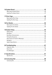
16 System Board 45 Removing the System Board 45 Installing The System Board 47 17 Drive Cage 49 Removing the Drive Cage 49 Installing The Drive Cage 51 18 Fan Shelter 53 Removing the Fan Shelter 53 Installing The Fan Shelter 53 19 System Setup 55 System Setup...55 Boot Menu...55 Boot Menu Enhancements 55 Timing Key Sequences...56 Beep Codes and Text Error Messages 57 Navigation...57 System Setup Options...57 20 Troubleshooting 67 Diagnostic LEDs...67 Beep Codes...74 Error Messages...77 21 Specifications 81 Specification...81 22 Contacting Dell 89 Contacting Dell...89
16 System Board 45 Removing the System Board 45 Installing The System Board 47 17 Drive Cage 49 Removing the Drive Cage 49 Installing The Drive Cage 51 18 Fan Shelter 53 Removing the Fan Shelter 53 Installing The Fan Shelter 53 19 System Setup 55 System Setup...55 Boot Menu...55 Boot Menu Enhancements 55 Timing Key Sequences...56 Beep Codes and Text Error Messages 57 Navigation...57 System Setup Options...57 20 Troubleshooting 67 Diagnostic LEDs...67 Beep Codes...74 Error Messages...77 21 Specifications 81 Specification...81 22 Contacting Dell 89 Contacting Dell...89

Owners Manual
Page 25
Disconnect the speaker cable from the fan shelter clip. 7. Press the speaker securing tab, and slide the speaker towards the right of the computer to release it. 25 Remove the drive cage. 5. Unthread the internal speaker cable from the system board. 6. Speaker 9 Removing the Internal Speaker 1. Remove the front bezel. 4. Follow the procedures in Before Working Inside Your Computer. 2. Remove the cover. 3.
Disconnect the speaker cable from the fan shelter clip. 7. Press the speaker securing tab, and slide the speaker towards the right of the computer to release it. 25 Remove the drive cage. 5. Unthread the internal speaker cable from the system board. 6. Speaker 9 Removing the Internal Speaker 1. Remove the front bezel. 4. Follow the procedures in Before Working Inside Your Computer. 2. Remove the cover. 3.

Owners Manual
Page 26
Install the drive cage. 6. Follow the procedures in After Working Inside Your Computer. 26 Press the speaker-securing tab and slide the speaker towards the left of the chassis rear. 2. Install the cover. 8. Thread the internal speaker cable into the fan shelter clip. 4. Connect the speaker cable to secure it. 3. Install the front bezel. 7. Installing The Speaker 1. Remove the speaker from the chassis. Place the speaker on the appropriate location of the computer to the system board. 5. 8.
Install the drive cage. 6. Follow the procedures in After Working Inside Your Computer. 26 Press the speaker-securing tab and slide the speaker towards the left of the chassis rear. 2. Install the cover. 8. Thread the internal speaker cable into the fan shelter clip. 4. Connect the speaker cable to secure it. 3. Install the front bezel. 7. Installing The Speaker 1. Remove the speaker from the chassis. Place the speaker on the appropriate location of the computer to the system board. 5. 8.

Owners Manual
Page 28
Lift the processor cover. 28 8. Lay the assembly with the fan facing downwards, and with the thermal grease facing upwards. 9. Lift the heat sink assembly upwards, and remove it . 10. Press the release lever down and then move it outward to release it from the retention hook that secures it from the computer.
Lift the processor cover. 28 8. Lay the assembly with the fan facing downwards, and with the thermal grease facing upwards. 9. Lift the heat sink assembly upwards, and remove it . 10. Press the release lever down and then move it outward to release it from the retention hook that secures it from the computer.

Owners Manual
Page 35
Remove the front bezel. 4. Remove the drive cage. 5. Remove the fan shelter. 6. Lift and remove the system fan from the system board. 7. Slide the grommets inward along the groove and pass through the chassis. 8. Follow the procedures in Before Working Inside Your Computer. 2. System Fan 13 Removing the System Fan 1. Remove the cover. 3. Disconnect the fan cable from the computer. 35
Remove the front bezel. 4. Remove the drive cage. 5. Remove the fan shelter. 6. Lift and remove the system fan from the system board. 7. Slide the grommets inward along the groove and pass through the chassis. 8. Follow the procedures in Before Working Inside Your Computer. 2. System Fan 13 Removing the System Fan 1. Remove the cover. 3. Disconnect the fan cable from the computer. 35

Owners Manual
Page 36
Install the drive cage. 7. Place the system fan in After Working Inside Your Computer. 36 Pass the four grommets through the chassis and slide outward along the grooves to the system board. 5. Install the cover. 9. Follow the procedures in the chassis. 3. Installing The System Fan 1. Insert the four grommets into the system fan. 2. Install the fan shelter. 6. Gently pry up the grommets from the system fan and remove it. Connect the fan cable to secure them in place. 4. Install the front bezel. 8. 9.
Install the drive cage. 7. Place the system fan in After Working Inside Your Computer. 36 Pass the four grommets through the chassis and slide outward along the grooves to the system board. 5. Install the cover. 9. Follow the procedures in the chassis. 3. Installing The System Fan 1. Insert the four grommets into the system fan. 2. Install the fan shelter. 6. Gently pry up the grommets from the system fan and remove it. Connect the fan cable to secure them in place. 4. Install the front bezel. 8. 9.

Owners Manual
Page 37
Follow the procedures in Before Working Inside Your Computer. 2. Remove the front bezel. 4. Disconnect the I /O panel/FlyWire cable from the system board. 7. Remove the single screw that secures the I /O) Panel 1. Remove the cover. 3. Unthread the I /O panel/FlyWire cable from the fan shelter clip and heat sink. 6. Remove the drive cage. 5. Input/Output Panel 14 Removing The Input/Output (I /O panel to the chassis. 37
Follow the procedures in Before Working Inside Your Computer. 2. Remove the front bezel. 4. Disconnect the I /O panel/FlyWire cable from the system board. 7. Remove the single screw that secures the I /O) Panel 1. Remove the cover. 3. Unthread the I /O panel/FlyWire cable from the fan shelter clip and heat sink. 6. Remove the drive cage. 5. Input/Output Panel 14 Removing The Input/Output (I /O panel to the chassis. 37
Owners Manual
Page 39
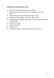
Connect the I /O panel towards the left of the computer to secure to the system board. 5. Install the cover. 9. Follow the procedures in After Working Inside Your Computer. 39 Slide the I /O panel/FlyWire cable to the chassis. 3. Thread the I /O panel into the fan shelter clip and the routing on the chassis front. 2. Tighten the screw to secure the I /O) Panel 1. Install the front bezel. 8. Insert the I /O panel/FlyWire cable into the slot on the heat sink. 6. Install the drive cage. 7. Installing The Input/Output (I /O panel to the chassis. 4.
Connect the I /O panel towards the left of the computer to secure to the system board. 5. Install the cover. 9. Follow the procedures in After Working Inside Your Computer. 39 Slide the I /O panel/FlyWire cable to the chassis. 3. Thread the I /O panel into the fan shelter clip and the routing on the chassis front. 2. Tighten the screw to secure the I /O) Panel 1. Install the front bezel. 8. Insert the I /O panel/FlyWire cable into the slot on the heat sink. 6. Install the drive cage. 7. Installing The Input/Output (I /O panel to the chassis. 4.

Owners Manual
Page 41
Disconnect the 4-pin power cable from the system board. 41 Power Supply 15 Removing the Power Supply 1. Remove the fan shelter. 6. Disconnect the 24-pin power cable from the system board. 7. Follow the procedures in Before Working Inside Your Computer. 2. Unthread the 4-pin power cable from the chassis clips. 8. Remove the drive cage. 5. Remove the front bezel. 4. Remove the cover. 3.
Disconnect the 4-pin power cable from the system board. 41 Power Supply 15 Removing the Power Supply 1. Remove the fan shelter. 6. Disconnect the 24-pin power cable from the system board. 7. Follow the procedures in Before Working Inside Your Computer. 2. Unthread the 4-pin power cable from the chassis clips. 8. Remove the drive cage. 5. Remove the front bezel. 4. Remove the cover. 3.

Owners Manual
Page 43
Use a Phillips screwdriver to tighten the three screws securing the power supply to the system board. 6. Connect the power cable to the back of the computer. 3. Install the front bezel. 9. Install the cover. 10. Connect the power cable to secure it. 2. Install the drive cage. 8. Follow the procedures in the chassis and slide outward to the system board. 4. Place the power supply in After Working Inside Your Computer. 43 Thread the power cable into the chassis clips. 5. Installing The Power Supply 1. Install the fan shelter. 7.
Use a Phillips screwdriver to tighten the three screws securing the power supply to the system board. 6. Connect the power cable to the back of the computer. 3. Install the front bezel. 9. Install the cover. 10. Connect the power cable to secure it. 2. Install the drive cage. 8. Follow the procedures in the chassis and slide outward to the system board. 4. Place the power supply in After Working Inside Your Computer. 43 Thread the power cable into the chassis clips. 5. Installing The Power Supply 1. Install the fan shelter. 7.

Owners Manual
Page 45
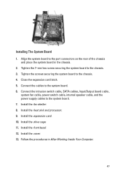
Remove the expansion cards. 6. Lift and release the expansion-card latch, to gain access to the system board, and move the cables away from the chassis. 9. Follow the procedures in Before Working Inside Your Computer. 2. Remove the fan shelter. 8. System Board 16 Removing the System Board 1. Remove the heat sink and processor. 7. Remove the front bezel. 4. Disconnect all the cables connected to the screws securing the system board. 45 Remove the drive cage. 5. Remove the cover. 3.
Remove the expansion cards. 6. Lift and release the expansion-card latch, to gain access to the system board, and move the cables away from the chassis. 9. Follow the procedures in Before Working Inside Your Computer. 2. Remove the fan shelter. 8. System Board 16 Removing the System Board 1. Remove the heat sink and processor. 7. Remove the front bezel. 4. Disconnect all the cables connected to the screws securing the system board. 45 Remove the drive cage. 5. Remove the cover. 3.
Owners Manual
Page 47
...board to the system board. 7. Close the expansion card latch. 5. Connect the intrusion switch cable, SATA cables, Input/Output board cable, system fan cable, power switch cable, internal speaker cable, and the power supply cables to the chassis. 3. Install the heat sink and processor. 9. ...Install the drive cage. 11. Follow the procedures in the chassis. 2. Install the fan shelter. 8. Install the expansion card. 10. Tighten the screws securing the system board to the system board. 6. Install the cover. 13. Connect...
...board to the system board. 7. Close the expansion card latch. 5. Connect the intrusion switch cable, SATA cables, Input/Output board cable, system fan cable, power switch cable, internal speaker cable, and the power supply cables to the chassis. 3. Install the heat sink and processor. 9. ...Install the drive cage. 11. Follow the procedures in the chassis. 2. Install the fan shelter. 8. Install the expansion card. 10. Tighten the screws securing the system board to the system board. 6. Install the cover. 13. Connect...

Owners Manual
Page 53
Fan Shelter 18 Removing the Fan Shelter 1. Lift the fan shelter free from the computer. Thread the cables into the computer. 2. Follow the procedures in Before Working Inside Your Computer. 2. Follow the procedures in After Working Inside Your Computer. 53 Installing The Fan Shelter 1. Install the cover. 4. Remove the cover. 3. Unthread the cables in the fan shelter clip. 4. Insert the fan shelter into the fan shelter clip. 3.
Fan Shelter 18 Removing the Fan Shelter 1. Lift the fan shelter free from the computer. Thread the cables into the computer. 2. Follow the procedures in Before Working Inside Your Computer. 2. Follow the procedures in After Working Inside Your Computer. 53 Installing The Fan Shelter 1. Install the cover. 4. Remove the cover. 3. Unthread the cables in the fan shelter clip. 4. Insert the fan shelter into the fan shelter clip. 3.
Owners Manual
Page 62
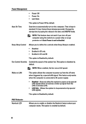
... Controls the speed of the system fan. Does not allow the system to define the controls when Deep Sleep is enabled. • Disabled • Enabled in S5 only • Enabled in standard ... the switch on by special LAN signals when it receives a wake-up from the LAN or wireless LAN. • LAN Only - NOTE: When enabled, the fan runs at full speed. POST Behavior Numlock LED Allows you turn on by default. Time is kept in S4 and S5 This option is Disabled...
... Controls the speed of the system fan. Does not allow the system to define the controls when Deep Sleep is enabled. • Disabled • Enabled in S5 only • Enabled in standard ... the switch on by special LAN signals when it receives a wake-up from the LAN or wireless LAN. • LAN Only - NOTE: When enabled, the fan runs at full speed. POST Behavior Numlock LED Allows you turn on by default. Time is kept in S4 and S5 This option is Disabled...
Owners Manual
Page 84
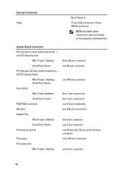
...Tower,Desktop four 7-pin connectors Small Form Factor two 7-pin connectors PS2/COM connector one 24-pin connectors Memory two 240-pin connectors System Fan Mini-Tower, Desktop two 3-pin connector Small Form Factor one 5-pin connector Front panel control one 16-pin, two 10-pin, and one... 5-pin connector Processor one 1155-pin connector Processor Fan Mini-Tower, Desktop one 4-pin connector 84 External Connectors Video Back Panel: 6 15-pin VGA connector, 19-pin HDMI connector NOTE: Available ...
...Tower,Desktop four 7-pin connectors Small Form Factor two 7-pin connectors PS2/COM connector one 24-pin connectors Memory two 240-pin connectors System Fan Mini-Tower, Desktop two 3-pin connector Small Form Factor one 5-pin connector Front panel control one 16-pin, two 10-pin, and one... 5-pin connector Processor one 1155-pin connector Processor Fan Mini-Tower, Desktop one 4-pin connector 84 External Connectors Video Back Panel: 6 15-pin VGA connector, 19-pin HDMI connector NOTE: Available ...


