User Manual
Page 1
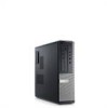
optical drive bay 3. Dell Optiplex 390 Setup And Features Information About Warnings WARNING: A WARNING indicates a potential for property damage, personal injury, or death. Front And Back View Figure 1. diagnostic lights (4) 6. USB 2.0 connectors (2) 9. power cable connector Regulatory Model :D12M, D07D, D04S Regulatory Type :D12M001, D07D001, D04S001 2011 - 05 headphone connector 4. hard-drive activity light 10. Mini-Tower - optical...
optical drive bay 3. Dell Optiplex 390 Setup And Features Information About Warnings WARNING: A WARNING indicates a potential for property damage, personal injury, or death. Front And Back View Figure 1. diagnostic lights (4) 6. USB 2.0 connectors (2) 9. power cable connector Regulatory Model :D12M, D07D, D04S Regulatory Type :D12M001, D07D001, D04S001 2011 - 05 headphone connector 4. hard-drive activity light 10. Mini-Tower - optical...
User Manual
Page 2
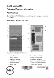
security cable slot 16. optical drive 2. USB 2.0 connectors (2) 5. hard-drive activity light 8. expansion card slots (4) 14. headphone connector 7. power-supply diagnostic button 2 Front And Back View Of Desktop 1. padlock ring 10. optical drive eject button 3. diagnostic lights (4) 9. back panel connectors 13. expansion card slots (4) Desktop - power cable connector 12. padlock ring Figure 2. security cable slot 11. power button 4. microphone connector 6. Front And Back View 15. power-supply diagnostic light 15. 13. back panel connectors 14.
security cable slot 16. optical drive 2. USB 2.0 connectors (2) 5. hard-drive activity light 8. expansion card slots (4) 14. headphone connector 7. power-supply diagnostic button 2 Front And Back View Of Desktop 1. padlock ring 10. optical drive eject button 3. diagnostic lights (4) 9. back panel connectors 13. expansion card slots (4) Desktop - power cable connector 12. padlock ring Figure 2. security cable slot 11. power button 4. microphone connector 6. Front And Back View 15. power-supply diagnostic light 15. 13. back panel connectors 14.
User Manual
Page 4
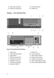
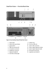
USB 2.0 connectors (2) 5. Front And Back View Of Small Form Factor 1. microphone connector 6. hard-drive activity light 9. power-supply diagnostic button 13. diagnostic lights (4) 8. power cable connector 12. optical drive eject button 3. headphone connector 7. back panel connectors 15. padlock ring 10. expansion card slots (2) 4 optical drive 2. security cable slot 11. Front And Back View Figure 4. power-supply diagnostic light 14. Small Form Factor - power button 4.
USB 2.0 connectors (2) 5. Front And Back View Of Small Form Factor 1. microphone connector 6. hard-drive activity light 9. power-supply diagnostic button 13. diagnostic lights (4) 8. power cable connector 12. optical drive eject button 3. headphone connector 7. back panel connectors 15. padlock ring 10. expansion card slots (2) 4 optical drive 2. security cable slot 11. Front And Back View Figure 4. power-supply diagnostic light 14. Small Form Factor - power button 4.
User Manual
Page 8
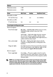
.... When the system power supply voltage is functional. blinking blue light indicates sleep state of computer: Power button light Blue light - Blinking blue light indicates that the computer is reading data from or writing data to the power connector (at support.dell.com/manuals. Diagnostic lights Four lights located on state; Memory Minimum memory Maximum memory 1 GB 8 GB...
.... When the system power supply voltage is functional. blinking blue light indicates sleep state of computer: Power button light Blue light - Blinking blue light indicates that the computer is reading data from or writing data to the power connector (at support.dell.com/manuals. Diagnostic lights Four lights located on state; Memory Minimum memory Maximum memory 1 GB 8 GB...
Technical Guide
Page 3
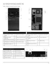
DELL™ OPTIPLEX™ 390 TECHNICAL GUIDEBOOK -FINAL MINI TOWER COMPUTER (MT) VIEW 1 6 10 7 11 15 2 12 16 8 3 4 9 5 13 14 FRONT VIEW BACK VIEW 1 Power Button, Power Light 6 Optical Drive (optional) 2 Optical Drive Bay (optional) 7 Optical Drive Eject Button 3 Microphone Connector 8 USB 2.0 Connectors (2) 4 Headphone Connector 9 Drive Activity Light 10 Power Supply Diagnostic 14 Expansion Card Slots(4) Light 11...
DELL™ OPTIPLEX™ 390 TECHNICAL GUIDEBOOK -FINAL MINI TOWER COMPUTER (MT) VIEW 1 6 10 7 11 15 2 12 16 8 3 4 9 5 13 14 FRONT VIEW BACK VIEW 1 Power Button, Power Light 6 Optical Drive (optional) 2 Optical Drive Bay (optional) 7 Optical Drive Eject Button 3 Microphone Connector 8 USB 2.0 Connectors (2) 4 Headphone Connector 9 Drive Activity Light 10 Power Supply Diagnostic 14 Expansion Card Slots(4) Light 11...
Technical Guide
Page 5
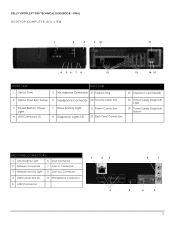
DELL™ OPTIPLEX™ 390 TECHNICAL GUIDEBOOK -FINAL DESKTOP COMPUTER (DT) VIEW 1 2 3 9 10 11 4 56 7 8 12 13 14 15 FRONT VIEW 1 Optical Drive BACK VIEW 5 Microphone Connector 9 Padlock Ring 13 Expansion Card Slots(4) 2 Optical Drive Eject Button 6 Headphone Connector 10 Security Cable Slot 3 Power Button, Power Light 4 USB Connectors (2) 7 Drive Activity Light 8 Diagnostic Lights (4) 11 Power Connectors 12...
DELL™ OPTIPLEX™ 390 TECHNICAL GUIDEBOOK -FINAL DESKTOP COMPUTER (DT) VIEW 1 2 3 9 10 11 4 56 7 8 12 13 14 15 FRONT VIEW 1 Optical Drive BACK VIEW 5 Microphone Connector 9 Padlock Ring 13 Expansion Card Slots(4) 2 Optical Drive Eject Button 6 Headphone Connector 10 Security Cable Slot 3 Power Button, Power Light 4 USB Connectors (2) 7 Drive Activity Light 8 Diagnostic Lights (4) 11 Power Connectors 12...
Technical Guide
Page 7
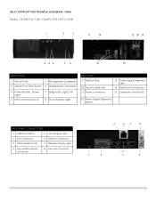
DELL™ OPTIPLEX™ 390 TECHNICAL GUIDEBOOK -FINAL SMALL FORM FACTOR COMPUTER (SFF) VIEW 1 2 3 9 10 11 12 13 4 56 7 8 14 15 FRONT VIEW 1 Optical Drive 5 Microphone Connector 2 Optical Drive Eject Button 6 Headphone Connector 3 Power Button, Power Light 4 USB 2.0 Connectors (2) 7 Diagnostic Lights (4) 8 Drive Activity Light BACK VIEW 9 Padlock Ring 10 Security Cable Slot 11 Power Connectors 13 Power Supply...
DELL™ OPTIPLEX™ 390 TECHNICAL GUIDEBOOK -FINAL SMALL FORM FACTOR COMPUTER (SFF) VIEW 1 2 3 9 10 11 12 13 4 56 7 8 14 15 FRONT VIEW 1 Optical Drive 5 Microphone Connector 2 Optical Drive Eject Button 6 Headphone Connector 3 Power Button, Power Light 4 USB 2.0 Connectors (2) 7 Diagnostic Lights (4) 8 Drive Activity Light BACK VIEW 9 Padlock Ring 10 Security Cable Slot 11 Power Connectors 13 Power Supply...

Owners Manual
Page 67
NOTE: The diagnostic lights will not blink when it with the system easier and more accurate. These diagnostic LEDs are turned on. • Ensure that the electrical outlet is not receiving power. • Re-seat the power cable in an attempt to help ... caused the POST routine to load, they turn off and are no other power protection devices to the power button. This has no longer visible. Diagnostic Light Patterns LED Power Button Problem Description Troubleshooting Steps The computer is either turned off , and will blink when the power button is amber or off...
NOTE: The diagnostic lights will not blink when it with the system easier and more accurate. These diagnostic LEDs are turned on. • Ensure that the electrical outlet is not receiving power. • Re-seat the power cable in an attempt to help ... caused the POST routine to load, they turn off and are no other power protection devices to the power button. This has no longer visible. Diagnostic Light Patterns LED Power Button Problem Description Troubleshooting Steps The computer is either turned off , and will blink when the power button is amber or off...
Owners Manual
Page 85
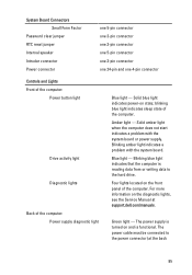
... computer: Power button light Drive activity light Diagnostic lights Back of the computer. Blinking amber light indicates a problem with the system board or power supply. The power supply is reading data from or writing data to the power connector (at support.dell.com/manuals. Amber light - Blue light - Green light - Solid blue light indicates power-on the diagnostic lights, see the Service...
... computer: Power button light Drive activity light Diagnostic lights Back of the computer. Blinking amber light indicates a problem with the system board or power supply. The power supply is reading data from or writing data to the power connector (at support.dell.com/manuals. Amber light - Blue light - Green light - Solid blue light indicates power-on the diagnostic lights, see the Service...


