User Manual
Page 1
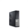
... Regulatory Model :D12M, D07D, D04S Regulatory Type :D12M001, D07D001, D04S001 2011 - 05 power button 2. headphone connector 4. USB 2.0 connectors (2) 9. power-supply diagnostic light 11. Front And Back View Figure 1. optical drive 7. diagnostic lights (4) 6. optical drive bay 3. Dell Optiplex 390 Setup And Features Information About Warnings WARNING: A WARNING indicates a potential for property damage, personal injury, or...
... Regulatory Model :D12M, D07D, D04S Regulatory Type :D12M001, D07D001, D04S001 2011 - 05 power button 2. headphone connector 4. USB 2.0 connectors (2) 9. power-supply diagnostic light 11. Front And Back View Figure 1. optical drive 7. diagnostic lights (4) 6. optical drive bay 3. Dell Optiplex 390 Setup And Features Information About Warnings WARNING: A WARNING indicates a potential for property damage, personal injury, or...
User Manual
Page 2
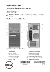
USB 2.0 connectors (2) 5. diagnostic lights (4) 9. power-supply diagnostic button 2 expansion card slots (4) Desktop - padlock ring Figure 2. power-supply diagnostic light 15. optical drive eject button 3. microphone connector 6. power button 4. power cable connector 12. optical drive 2. headphone connector 7. hard-drive activity light 8. security cable slot 11. expansion card slots (4) 14. back panel connectors 14. padlock ring 10. 13. Front And Back View 15. security cable slot 16. Front And Back View Of Desktop 1. back panel connectors 13.
USB 2.0 connectors (2) 5. diagnostic lights (4) 9. power-supply diagnostic button 2 expansion card slots (4) Desktop - padlock ring Figure 2. power-supply diagnostic light 15. optical drive eject button 3. microphone connector 6. power button 4. power cable connector 12. optical drive 2. headphone connector 7. hard-drive activity light 8. security cable slot 11. expansion card slots (4) 14. back panel connectors 14. padlock ring 10. 13. Front And Back View 15. security cable slot 16. Front And Back View Of Desktop 1. back panel connectors 13.
User Manual
Page 3
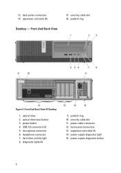
Mini-Tower And Desktop - Back Panel Figure 3. link integrity light 2. network activity light 4. USB 2.0 connectors (6) 7. line-in connector 5. line-out connector 6. network connector 3. VGA connector 9. microphone connector 3 Back Panel View of Mini-Tower And Desktop 1. HDMI connector 8.
Mini-Tower And Desktop - Back Panel Figure 3. link integrity light 2. network activity light 4. USB 2.0 connectors (6) 7. line-in connector 5. line-out connector 6. network connector 3. VGA connector 9. microphone connector 3 Back Panel View of Mini-Tower And Desktop 1. HDMI connector 8.
User Manual
Page 4
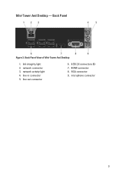
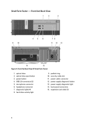
optical drive eject button 3. headphone connector 7. hard-drive activity light 9. padlock ring 10. power button 4. diagnostic lights (4) 8. optical drive 2. USB 2.0 connectors (2) 5. security cable slot 11. back panel connectors 15. Small Form Factor - power-supply diagnostic light 14. expansion card slots (2) 4 Front And Back View Of Small Form Factor 1. power-supply diagnostic button 13. microphone connector 6. power cable connector 12. Front And Back View Figure 4.
optical drive eject button 3. headphone connector 7. hard-drive activity light 9. padlock ring 10. power button 4. diagnostic lights (4) 8. optical drive 2. USB 2.0 connectors (2) 5. security cable slot 11. back panel connectors 15. Small Form Factor - power-supply diagnostic light 14. expansion card slots (2) 4 Front And Back View Of Small Form Factor 1. power-supply diagnostic button 13. microphone connector 6. power cable connector 12. Front And Back View Figure 4.

User Manual
Page 5
... connector 5. line-in this section, read the safety information that shipped with your computer. network connector 3. HDMI connector 6. For additional best practices information, see www.dell.com/regulatory_compliance. link integrity light 2. NOTE: Some devices may not be included if you begin any of the procedures in /microphone connector Quick Setup WARNING...
... connector 5. line-in this section, read the safety information that shipped with your computer. network connector 3. HDMI connector 6. For additional best practices information, see www.dell.com/regulatory_compliance. link integrity light 2. NOTE: Some devices may not be included if you begin any of the procedures in /microphone connector Quick Setup WARNING...
User Manual
Page 6
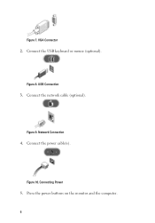
Network Connection 4. Connecting Power 5. Press the power buttons on the monitor and the computer. 6 Connect the power cable(s). VGA Connector 2. Connect the USB keyboard or mouse (optional). Figure 9. Figure 10. Figure 8. USB Connection 3. Figure 7. Connect the network cable (optional).
Network Connection 4. Connecting Power 5. Press the power buttons on the monitor and the computer. 6 Connect the power cable(s). VGA Connector 2. Connect the USB keyboard or mouse (optional). Figure 9. Figure 10. Figure 8. USB Connection 3. Figure 7. Connect the network cable (optional).
Technical Guide
Page 3
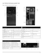
DELL™ OPTIPLEX™ 390 TECHNICAL GUIDEBOOK -FINAL MINI TOWER COMPUTER (MT) VIEW 1 6 10 7 11 15 2 12 16 8 3 4 9 5 13 14 FRONT VIEW BACK VIEW 1 Power Button, Power Light 6 Optical Drive (optional) 2 Optical Drive Bay (optional) 7 Optical Drive Eject Button 3 Microphone Connector 8 USB 2.0 Connectors (2) 4 Headphone Connector 9 ...PANEL CONNECTORS 1 Link Integrity Light 6 VGA Connector 2 Network Connector 7 Line-in Connector 3 Network Activity Light 8 Line-out Connector 4 USB Connectors (6) 9 Microphone Connector 5 HDMI Connector 1 2 3 4 8 7 5 6 9 3
DELL™ OPTIPLEX™ 390 TECHNICAL GUIDEBOOK -FINAL MINI TOWER COMPUTER (MT) VIEW 1 6 10 7 11 15 2 12 16 8 3 4 9 5 13 14 FRONT VIEW BACK VIEW 1 Power Button, Power Light 6 Optical Drive (optional) 2 Optical Drive Bay (optional) 7 Optical Drive Eject Button 3 Microphone Connector 8 USB 2.0 Connectors (2) 4 Headphone Connector 9 ...PANEL CONNECTORS 1 Link Integrity Light 6 VGA Connector 2 Network Connector 7 Line-in Connector 3 Network Activity Light 8 Line-out Connector 4 USB Connectors (6) 9 Microphone Connector 5 HDMI Connector 1 2 3 4 8 7 5 6 9 3
Technical Guide
Page 4
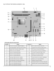
DELL™ OPTIPLEX™ 390 TECHNICAL GUIDEBOOK -FINAL MT System Board Components Number Name 1 Front IO connector (FRONTPANEL)) 2 Internal Speaker Connector (INT_SPKR) 3 System fan Connector (FAN_SYS1) 4 SATA 1 Connector(SATA1) 5 SATA 0 Connector(SATA0) 6 SATA 2 Connector(SATA2) 7 SATA 3 Connector(SATA3) 8 Internal USB Connector (USBF1) 9 Internal USB Connector (USBF1) 10 Internal Audio Connector (AUDIOF1) 11 PCI-e 1x Connector (SLOT4...
DELL™ OPTIPLEX™ 390 TECHNICAL GUIDEBOOK -FINAL MT System Board Components Number Name 1 Front IO connector (FRONTPANEL)) 2 Internal Speaker Connector (INT_SPKR) 3 System fan Connector (FAN_SYS1) 4 SATA 1 Connector(SATA1) 5 SATA 0 Connector(SATA0) 6 SATA 2 Connector(SATA2) 7 SATA 3 Connector(SATA3) 8 Internal USB Connector (USBF1) 9 Internal USB Connector (USBF1) 10 Internal Audio Connector (AUDIOF1) 11 PCI-e 1x Connector (SLOT4...
Technical Guide
Page 5
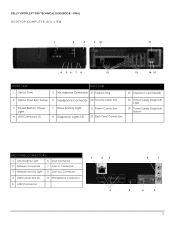
DELL™ OPTIPLEX™ 390 TECHNICAL GUIDEBOOK -FINAL DESKTOP COMPUTER (DT) VIEW 1 2 3 9 10 11 4 56 7 8 12 13 14 15 FRONT VIEW 1 Optical Drive BACK VIEW 5 Microphone Connector 9 Padlock Ring 13 Expansion Card Slots(4) 2 Optical Drive Eject Button 6 Headphone Connector 10 Security Cable Slot 3 Power Button, Power Light 4 USB Connectors (2) 7 Drive Activity Light 8 Diagnostic Lights (4) 11...
DELL™ OPTIPLEX™ 390 TECHNICAL GUIDEBOOK -FINAL DESKTOP COMPUTER (DT) VIEW 1 2 3 9 10 11 4 56 7 8 12 13 14 15 FRONT VIEW 1 Optical Drive BACK VIEW 5 Microphone Connector 9 Padlock Ring 13 Expansion Card Slots(4) 2 Optical Drive Eject Button 6 Headphone Connector 10 Security Cable Slot 3 Power Button, Power Light 4 USB Connectors (2) 7 Drive Activity Light 8 Diagnostic Lights (4) 11...
Technical Guide
Page 6
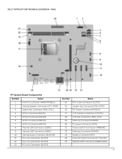
DELL™ OPTIPLEX™ 390 TECHNICAL GUIDEBOOK -FINAL DT System Board Components Number Name 1 Front IO connector (FRONTPANEL)) 2 Internal Speaker Connector (INT_SPKR) 3 System fan Connector (FAN_SYS1) 4 SATA 1 Connector(SATA1) 5 SATA 0 Connector(SATA0) 6 SATA 2 Connector(SATA2) 7 SATA 3 Connector(SATA3) 8 Internal USB Connector (USBF1) 9 Internal USB Connector (USBF1) 10 Internal Audio Connector (AUDIOF1) 11 PCI-e 1x Connector (SLOT4...
DELL™ OPTIPLEX™ 390 TECHNICAL GUIDEBOOK -FINAL DT System Board Components Number Name 1 Front IO connector (FRONTPANEL)) 2 Internal Speaker Connector (INT_SPKR) 3 System fan Connector (FAN_SYS1) 4 SATA 1 Connector(SATA1) 5 SATA 0 Connector(SATA0) 6 SATA 2 Connector(SATA2) 7 SATA 3 Connector(SATA3) 8 Internal USB Connector (USBF1) 9 Internal USB Connector (USBF1) 10 Internal Audio Connector (AUDIOF1) 11 PCI-e 1x Connector (SLOT4...
Technical Guide
Page 7
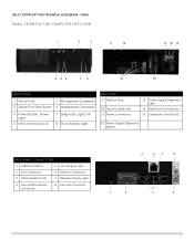
DELL™ OPTIPLEX™ 390 TECHNICAL GUIDEBOOK -FINAL SMALL FORM FACTOR COMPUTER (SFF) VIEW 1 2 3 9 10 11 12 13 4 56 7 8 14 15 FRONT VIEW 1 Optical Drive 5 Microphone Connector 2 Optical Drive Eject Button 6 Headphone Connector 3 Power Button, Power Light 4 USB 2.0 Connectors (2) 7 Diagnostic Lights (4) 8 Drive Activity Light ... Diagnostic Button BACK PANEL CONNECTORS 1 HDMI Connector 5 Link Integrity Light 2 VGA Connector 6 Network Connector 3 USB Connectors (6) 7 Network Activity Light 4 Line-in/Microphone Connector 8 Line-out Connector 5 6 7 8 1 2 3 4 7
DELL™ OPTIPLEX™ 390 TECHNICAL GUIDEBOOK -FINAL SMALL FORM FACTOR COMPUTER (SFF) VIEW 1 2 3 9 10 11 12 13 4 56 7 8 14 15 FRONT VIEW 1 Optical Drive 5 Microphone Connector 2 Optical Drive Eject Button 6 Headphone Connector 3 Power Button, Power Light 4 USB 2.0 Connectors (2) 7 Diagnostic Lights (4) 8 Drive Activity Light ... Diagnostic Button BACK PANEL CONNECTORS 1 HDMI Connector 5 Link Integrity Light 2 VGA Connector 6 Network Connector 3 USB Connectors (6) 7 Network Activity Light 4 Line-in/Microphone Connector 8 Line-out Connector 5 6 7 8 1 2 3 4 7
Technical Guide
Page 12
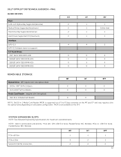
NOTE: Add in 1 Media Card Reader (MCR) is not available on selectable configuration. DELL™ OPTIPLEX™ 390 TECHNICAL GUIDEBOOK -FINAL HARD DRIVES MT Bays: 5.25-inch Optical Bay Supported (External) 2 Optical Drives Supported (maximum) 2 Hard Drive ...-ROM3 SATA 1.5Gbit/s Media Card Reader: (requires slim line optical) Dell 19 in 1 Media Card Reader MT DT SFF X X X X X X X X NOTE: Dell 19 in card location and priority: PCIe x16: GFX, USB 3.0, Serial, Parallel/Serial, NIC, Wireless; PCIe x1: USB 3.0, Serial, Parallel/Serial, NIC, Wireless MT DT SFF PCIe x16 ...
NOTE: Add in 1 Media Card Reader (MCR) is not available on selectable configuration. DELL™ OPTIPLEX™ 390 TECHNICAL GUIDEBOOK -FINAL HARD DRIVES MT Bays: 5.25-inch Optical Bay Supported (External) 2 Optical Drives Supported (maximum) 2 Hard Drive ...-ROM3 SATA 1.5Gbit/s Media Card Reader: (requires slim line optical) Dell 19 in 1 Media Card Reader MT DT SFF X X X X X X X X NOTE: Dell 19 in card location and priority: PCIe x16: GFX, USB 3.0, Serial, Parallel/Serial, NIC, Wireless; PCIe x1: USB 3.0, Serial, Parallel/Serial, NIC, Wireless MT DT SFF PCIe x16 ...
Technical Guide
Page 13
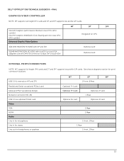
... LP card 1 Rear Optional LP card 1 Rear 1 Rear 1 Front, 1 Rear 1 Rear 1 Front, 1 Rear 13 See chassis diagrams section for port/ connector locations USB 2.0 (1 internal on CPU 1GB AMD RADEON HD 6450 with DP and DVI 512MB AMD RADEON HD 6350 with dual DVI or dual VGA (adapters convert... Optional card EXTERNAL PORTS/CONNECTORS NOTE: MT supports full height (FH) cards and DT and SFF supports low profile (LP) cards. DELL™ OPTIPLEX™ 390 TECHNICAL GUIDEBOOK -FINAL GRAPHICS/VIDEO CONTROLLER NOTE: MT supports full height (FH) cards and DT and SFF supports low profile (LP) cards....
... LP card 1 Rear Optional LP card 1 Rear 1 Rear 1 Front, 1 Rear 1 Rear 1 Front, 1 Rear 13 See chassis diagrams section for port/ connector locations USB 2.0 (1 internal on CPU 1GB AMD RADEON HD 6450 with DP and DVI 512MB AMD RADEON HD 6350 with dual DVI or dual VGA (adapters convert... Optional card EXTERNAL PORTS/CONNECTORS NOTE: MT supports full height (FH) cards and DT and SFF supports low profile (LP) cards. DELL™ OPTIPLEX™ 390 TECHNICAL GUIDEBOOK -FINAL GRAPHICS/VIDEO CONTROLLER NOTE: MT supports full height (FH) cards and DT and SFF supports low profile (LP) cards....
Technical Guide
Page 14
... Definition Audio Codec Internal Dell Business Audio Speaker Dell AX210 2.0 Desktop Speakers Dell AX510/AX510PA Flat Panel Soundbar Speakers Dell USB Entry Keyboard with optional palmrest Dell Multimedia Pro Keyboard Dell USB Optical Mouse Dell Laser Mouse MT DT ...SFF Integrated on system board Broadcom NetXtreme 10/100/1000 PCIe Gigabit Networking Card Optional card 1 This term does not connote an actual operating speed of 1 Gb/sec. DELL™ OPTIPLEX™ 390...
... Definition Audio Codec Internal Dell Business Audio Speaker Dell AX210 2.0 Desktop Speakers Dell AX510/AX510PA Flat Panel Soundbar Speakers Dell USB Entry Keyboard with optional palmrest Dell Multimedia Pro Keyboard Dell USB Optical Mouse Dell Laser Mouse MT DT ...SFF Integrated on system board Broadcom NetXtreme 10/100/1000 PCIe Gigabit Networking Card Optional card 1 This term does not connote an actual operating speed of 1 Gb/sec. DELL™ OPTIPLEX™ 390...
Technical Guide
Page 23
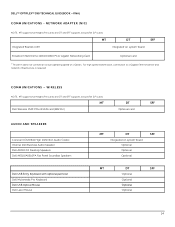
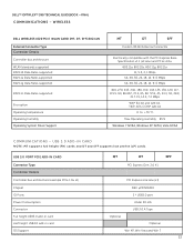
... CARD NOTE: MT supports full height (FH) cards and DT and SFF supports low profile (LP) cards. USB 3.0 PORT PCIE ADD-IN CARD Connector Type Controller Details Controller bus architecture (example PCIe 1.0a x1) Chipset IO Ports Power Consumption Connector... X1 PCI Express one lane (x1) NEC µPD720200 2 * USB3.0 port Under 30 mA USB 3.0 A Type Optional Optional Win XP, Win Vista and Win 7 23 DELL™ OPTIPLEX™ 390 TECHNICAL GUIDEBOOK -FINAL COMMUNICATIONS - WIRELESS DELL WIRELESS 1520 PCIE WLAN CARD (MT, DT, SFF) 802.11N External Connector Type Controller Details Controller ...
... CARD NOTE: MT supports full height (FH) cards and DT and SFF supports low profile (LP) cards. USB 3.0 PORT PCIE ADD-IN CARD Connector Type Controller Details Controller bus architecture (example PCIe 1.0a x1) Chipset IO Ports Power Consumption Connector... X1 PCI Express one lane (x1) NEC µPD720200 2 * USB3.0 port Under 30 mA USB 3.0 A Type Optional Optional Win XP, Win Vista and Win 7 23 DELL™ OPTIPLEX™ 390 TECHNICAL GUIDEBOOK -FINAL COMMUNICATIONS - WIRELESS DELL WIRELESS 1520 PCIE WLAN CARD (MT, DT, SFF) 802.11N External Connector Type Controller Details Controller ...
Technical Guide
Page 33
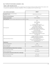
...supported via a F5 to 95% RH 33 W x H) 3.99/(10.13cm)/1.0/(2.54cm) Weight (max) pounds/kilograms ~155g Interface type and speed USB 2.0, 480Mb/s Media Supported ( maximum capacity supported will vary by Flash Media Types) Media Supported Support Specification Versions: CF I CF II Micro Drive... on the SFF and USFF chassis. 19 IN 1 MEDIA CARD READER MT/DT External Dimensions inches/(centimeters) (With Bezel - DELL™ OPTIPLEX™ 390 TECHNICAL GUIDEBOOK -FINAL MEDIA CARD READER (MCR) NOTE: Dell 19 in 1 Media Card Reader (MCR) is not available on selectable configuration.
...supported via a F5 to 95% RH 33 W x H) 3.99/(10.13cm)/1.0/(2.54cm) Weight (max) pounds/kilograms ~155g Interface type and speed USB 2.0, 480Mb/s Media Supported ( maximum capacity supported will vary by Flash Media Types) Media Supported Support Specification Versions: CF I CF II Micro Drive... on the SFF and USFF chassis. 19 IN 1 MEDIA CARD READER MT/DT External Dimensions inches/(centimeters) (With Bezel - DELL™ OPTIPLEX™ 390 TECHNICAL GUIDEBOOK -FINAL MEDIA CARD READER (MCR) NOTE: Dell 19 in 1 Media Card Reader (MCR) is not available on selectable configuration.
Technical Guide
Page 34
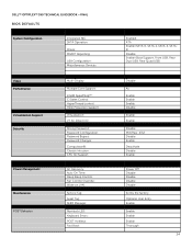
DELL™ OPTIPLEX™ 390 TECHNICAL GUIDEBOOK -FINAL BIOS DEFAULTS System Configuration Integrated NIC: SATA Operation: Drives: SMART Reporting: USB Configuration: Miscellaneous Devices: Video Performance Virtualization Support Security Power Management Maintenance POST Behavior Multi-Display: Multiple ... POST HotKeys: Fast Boot: Enabled ATA Enable (SATA-0, SATA-1, SATA-2, SATA3) Disable Enable (Boot Support, Front USB, Rear Dual USB, Rear Quad USB) Disable All Enable Enable Enable Disable Enable Enable Disable Min/Max: 4/32 Disable Enable Deactivate Disable Enable Power Off Disable...
DELL™ OPTIPLEX™ 390 TECHNICAL GUIDEBOOK -FINAL BIOS DEFAULTS System Configuration Integrated NIC: SATA Operation: Drives: SMART Reporting: USB Configuration: Miscellaneous Devices: Video Performance Virtualization Support Security Power Management Maintenance POST Behavior Multi-Display: Multiple ... POST HotKeys: Fast Boot: Enabled ATA Enable (SATA-0, SATA-1, SATA-2, SATA3) Disable Enable (Boot Support, Front USB, Rear Dual USB, Rear Quad USB) Disable All Enable Enable Enable Disable Enable Enable Disable Min/Max: 4/32 Disable Enable Deactivate Disable Enable Power Off Disable...
Owners Manual
Page 58
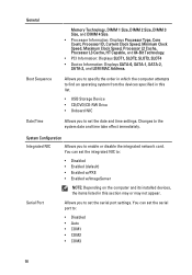
... set the serial port settings. Allows you to set the serial port to find an operating system from the devices specified in this list. • USB Storage Device • CD/DVD/CD-RW Drive • Onboard NIC Allows you to specify the order in which the computer attempts to : • Disabled...
... set the serial port settings. Allows you to set the serial port to find an operating system from the devices specified in this list. • USB Storage Device • CD/DVD/CD-RW Drive • Onboard NIC Allows you to specify the order in which the computer attempts to : • Disabled...

Owners Manual
Page 59
Security Administrative Password System Password Allows you to enable or disable the integrated USB controller for integrated drives are reported during system startup. This option is disabled by default. 59 Allows you to enable or disable the...on-board: • SATA-0 • SATA-1 • SATA-2 • SATA-3 Smart Reporting USB Configuration This field controls whether hard drive errors for : • Boot Support • Rear Dual USB Ports • Front USB Ports • Rear Quad USB Ports Miscellaneous Devices Allows you to set restricted access to be assigned and verified...
Security Administrative Password System Password Allows you to enable or disable the integrated USB controller for integrated drives are reported during system startup. This option is disabled by default. 59 Allows you to enable or disable the...on-board: • SATA-0 • SATA-1 • SATA-2 • SATA-3 Smart Reporting USB Configuration This field controls whether hard drive errors for : • Boot Support • Rear Dual USB Ports • Front USB Ports • Rear Quad USB Ports Miscellaneous Devices Allows you to set restricted access to be assigned and verified...
Owners Manual
Page 72
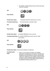
Problem Description Troubleshooting Steps LED A possible hard drive failure has occurred. Power Button Problem Description A possible USB failure has occurred. If the computer starts normally, continue to install additional memory modules (one module (see your computer. LED ...Problem Description No memory modules are installed, remove the modules (see your service manual) and restart the computer. Troubleshooting Steps Re-install all USB devices and check all power and data cables. Troubleshooting Steps • If two or more memory modules are detected. Re-seat all cable...
Problem Description Troubleshooting Steps LED A possible hard drive failure has occurred. Power Button Problem Description A possible USB failure has occurred. If the computer starts normally, continue to install additional memory modules (one module (see your computer. LED ...Problem Description No memory modules are installed, remove the modules (see your service manual) and restart the computer. Troubleshooting Steps Re-install all USB devices and check all power and data cables. Troubleshooting Steps • If two or more memory modules are detected. Re-seat all cable...


