User Manual
Page 8
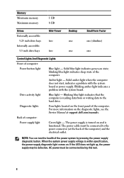
...blinking blue light indicates sleep state of the power system by pressing the power-supply diagnostic button. Solid amber light when the computer does not start, indicates a problem with the system board. Blinking amber light indicates a problem with the system board or power supply. Drive activity light Blue...- For more information on . When the system power supply voltage is reading data from or writing data to the power connector (at support.dell.com/manuals. If the LED does not light up, the power supply may be connected during this test. 8 The power cable must be...
...blinking blue light indicates sleep state of the power system by pressing the power-supply diagnostic button. Solid amber light when the computer does not start, indicates a problem with the system board. Blinking amber light indicates a problem with the system board or power supply. Drive activity light Blue...- For more information on . When the system power supply voltage is reading data from or writing data to the power connector (at support.dell.com/manuals. If the LED does not light up, the power supply may be connected during this test. 8 The power cable must be...

User Manual
Page 10
... without the written permission of Advanced Micro Devices, Inc. Reproduction of these materials in any manner whatsoever without notice. © 2011 Dell Inc. AMD® is a registered trademark and AMD Opteron™, AMD Phenom™, AMD Sempron™, AMD Athlon™, ATI...;, Windows Vista®, the Windows Vista start button, and 10 only) • End User License Agreement Information in this text: Dell™, the DELL logo, Dell Precision™, Precision ON™, ExpressCharge™, Latitude™, Latitude ON™, OptiPlex™, Vostro™, and Wi-Fi ...
... without the written permission of Advanced Micro Devices, Inc. Reproduction of these materials in any manner whatsoever without notice. © 2011 Dell Inc. AMD® is a registered trademark and AMD Opteron™, AMD Phenom™, AMD Sempron™, AMD Athlon™, ATI...;, Windows Vista®, the Windows Vista start button, and 10 only) • End User License Agreement Information in this text: Dell™, the DELL logo, Dell Precision™, Precision ON™, ExpressCharge™, Latitude™, Latitude ON™, OptiPlex™, Vostro™, and Wi-Fi ...
Technical Guide
Page 9
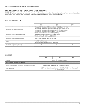
...EEPROM 9 For more information regarding the configuration of your computer, click Start>Help and Support and select the option to view information about your ... Business SP2 (32 and 64 bit), Windows Vista® Ultimate SP2 (32 bit) Basic Driver support only via Dell.com FreeDOS for (N-series), Ubuntu® Linux version 10.10 (China only) X X X CHIPSET Chipset Non-volatile...located at SPI_FLASH on chipset LOM configuration contained within SPI_FLASH - DELL™ OPTIPLEX™ 390 TECHNICAL GUIDEBOOK -FINAL MARKETING SYSTEM CONFIGURATIONS NOTE: Offerings may vary by country.
...EEPROM 9 For more information regarding the configuration of your computer, click Start>Help and Support and select the option to view information about your ... Business SP2 (32 and 64 bit), Windows Vista® Ultimate SP2 (32 bit) Basic Driver support only via Dell.com FreeDOS for (N-series), Ubuntu® Linux version 10.10 (China only) X X X CHIPSET Chipset Non-volatile...located at SPI_FLASH on chipset LOM configuration contained within SPI_FLASH - DELL™ OPTIPLEX™ 390 TECHNICAL GUIDEBOOK -FINAL MARKETING SYSTEM CONFIGURATIONS NOTE: Offerings may vary by country.
Owners Manual
Page 2
...States and/or other countries. Microsoft®, Windows®, MS-DOS®, Windows Vista®, the Windows Vista start button, and Office Outlook® are trademarks of Dell Inc. Wi-Fi® is a trademark owned by the Blu-ray Disc Association (BDA) and licensed for ... Compatibility Alliance, Inc. Other trademarks and trade names may be used in this text: Dell™, the DELL logo, Dell Precision™, Precision ON™,ExpressCharge™, Latitude™, Latitude ON™, OptiPlex™, Vostro™, and Wi-Fi Catcher™ are either the entities claiming the...
...States and/or other countries. Microsoft®, Windows®, MS-DOS®, Windows Vista®, the Windows Vista start button, and Office Outlook® are trademarks of Dell Inc. Wi-Fi® is a trademark owned by the Blu-ray Disc Association (BDA) and licensed for ... Compatibility Alliance, Inc. Other trademarks and trade names may be used in this text: Dell™, the DELL logo, Dell Precision™, Precision ON™,ExpressCharge™, Latitude™, Latitude ON™, OptiPlex™, Vostro™, and Wi-Fi Catcher™ are either the entities claiming the...

Owners Manual
Page 8
... dissipate static electricity, which could harm internal components. Disconnect your computer (see Turning Off Your Computer). Shut down the operating system: • In Windows 7: Click Start , then click Shut Down. • In Windows Vista: 8
... dissipate static electricity, which could harm internal components. Disconnect your computer (see Turning Off Your Computer). Shut down the operating system: • In Windows 7: Click Start , then click Shut Down. • In Windows Vista: 8
Owners Manual
Page 9
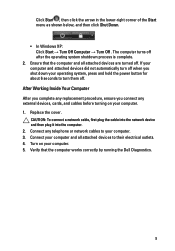
Ensure that the computer works correctly by running the Dell Diagnostics. 9 Connect any external devices, cards, and cables before turning on your computer. 1. The computer turns off . Turn on your computer. 5. Verify that the computer ... when you connect any telephone or network cables to turn them off. Click Start , then click the arrow in the lower-right corner of the Start menu as shown below, and then click Shut Down. • In Windows XP: Click Start → Turn Off Computer → Turn Off . Replace the cover. Connect your...
Ensure that the computer works correctly by running the Dell Diagnostics. 9 Connect any external devices, cards, and cables before turning on your computer. 1. The computer turns off . Turn on your computer. 5. Verify that the computer ... when you connect any telephone or network cables to turn them off. Click Start , then click the arrow in the lower-right corner of the Start menu as shown below, and then click Shut Down. • In Windows XP: Click Start → Turn Off Computer → Turn Off . Replace the cover. Connect your...
Owners Manual
Page 62
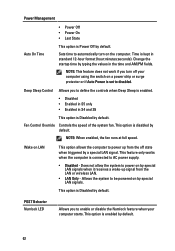
.... Does not allow the system to power on a power strip or surge protector or if Auto Power is set to automatically turn off your computer starts. This option is disabled by typing the values in standard 12-hour format (hour:minutes:seconds). This option is Disabled by default. 62 This option...
.... Does not allow the system to power on a power strip or surge protector or if Auto Power is set to automatically turn off your computer starts. This option is disabled by typing the values in standard 12-hour format (hour:minutes:seconds). This option is Disabled by default. 62 This option...
Owners Manual
Page 63
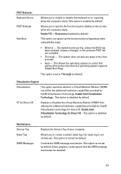
This allows the operating system to display on the screen when the computer starts. This option is disabled by bypassing some compatibility steps: • Minimal - Controls the SERR message mechanism. Boot menu (enabled by default) This option can utilize ... Tag Asset Tag SERR Messages Displays the Service Tag of your computer. Allows you to enable or disable the keyboard error reporting when the computer starts. This option is not set to Thorough by default. Enable Intel Virtualization Technology for direct I/O. Some graphics cards require that the SERR message mechanism be...
This allows the operating system to display on the screen when the computer starts. This option is disabled by bypassing some compatibility steps: • Minimal - Controls the SERR message mechanism. Boot menu (enabled by default) This option can utilize ... Tag Asset Tag SERR Messages Displays the Service Tag of your computer. Allows you to enable or disable the keyboard error reporting when the computer starts. This option is not set to Thorough by default. Enable Intel Virtualization Technology for direct I/O. Some graphics cards require that the SERR message mechanism be...

Owners Manual
Page 67
Once the operating system starts to the power button. Diagnostic Light Patterns LED Power Button Problem Description Troubleshooting Steps The computer is either turned off or is not receiving power. &#...
Once the operating system starts to the power button. Diagnostic Light Patterns LED Power Button Problem Description Troubleshooting Steps The computer is either turned off or is not receiving power. &#...
Owners Manual
Page 69
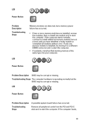
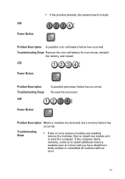
...If two or more memory modules are detected, but the BIOS may be corrupt or missing. If the computer starts normally, continue to a different DIMM connector and re-start the computer. • If available, install verified working memory of the same type into your computer. LED ... possible system board failure has occurred. Remove all modules without error. If the computer boots, 69 If only one module and re-start the computer. LED Power Button Problem Description Troubleshooting Steps Memory modules are installed, remove the modules, then re-install one memory module ...
...If two or more memory modules are detected, but the BIOS may be corrupt or missing. If the computer starts normally, continue to a different DIMM connector and re-start the computer. • If available, install verified working memory of the same type into your computer. LED ... possible system board failure has occurred. Remove all modules without error. If the computer boots, 69 If only one module and re-start the computer. LED Power Button Problem Description Troubleshooting Steps Memory modules are installed, remove the modules, then re-install one memory module ...

Owners Manual
Page 70
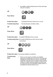
... connector not installed properly. Troubleshooting Steps Re-seat the 2x2 power connector from the PCI and PCI-E slots and re-start the computer. Remove all internal and external peripherals, and re-start the computer. LED Power Button add the peripheral cards back one by one until you find the bad one . 70...
... connector not installed properly. Troubleshooting Steps Re-seat the 2x2 power connector from the PCI and PCI-E slots and re-start the computer. Remove all internal and external peripherals, and re-start the computer. LED Power Button add the peripheral cards back one by one until you find the bad one . 70...
Owners Manual
Page 71
Troubleshooting Steps Remove the coin cell battery for one module and re-start the computer. Troubleshooting Steps • If two or more memory modules are detected, but a memory failure has occurred. LED Power Button Problem ...Description Troubleshooting Steps LED A possible processor failure has occurred. Problem Description A possible coin cell battery failure has occurred. If the computer starts normally, continue to install additional memory modules (one at a time) until you have identified a faulty module or reinstalled all modules without error. 71 ...
Troubleshooting Steps Remove the coin cell battery for one module and re-start the computer. Troubleshooting Steps • If two or more memory modules are detected, but a memory failure has occurred. LED Power Button Problem ...Description Troubleshooting Steps LED A possible processor failure has occurred. Problem Description A possible coin cell battery failure has occurred. If the computer starts normally, continue to install additional memory modules (one at a time) until you have identified a faulty module or reinstalled all modules without error. 71 ...
Owners Manual
Page 72
... occurred. LED Power Button Problem Description No memory modules are installed, remove the modules (see your service manual) and restart the computer. If the computer starts normally, continue to install additional memory modules (one module (see your computer. Troubleshooting Steps Re-install all USB devices and check all power and data...
... occurred. LED Power Button Problem Description No memory modules are installed, remove the modules (see your service manual) and restart the computer. If the computer starts normally, continue to install additional memory modules (one module (see your computer. Troubleshooting Steps Re-install all USB devices and check all power and data...
Owners Manual
Page 73
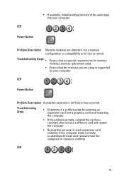
... Steps • Determine if a conflict exists by your computer. LED 73 Ensure that no special requirements for memory module/connector placement exist. If the computer starts normally, troubleshoot the last card removed from the computer for each expansion card installed. LED Power Button • If available, install working memory of the...
... Steps • Determine if a conflict exists by your computer. LED 73 Ensure that no special requirements for memory module/connector placement exist. If the computer starts normally, troubleshoot the last card removed from the computer for each expansion card installed. LED Power Button • If available, install working memory of the...
Owners Manual
Page 74
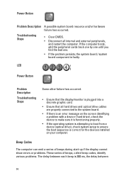
Beep Codes The computer can emit a series of beeps during start-up if the display cannot show errors or problems. These series of beeps, called beep codes, identify various problems. The delay between 74 LED Power ...
Beep Codes The computer can emit a series of beeps during start-up if the display cannot show errors or problems. These series of beeps, called beep codes, identify various problems. The delay between 74 LED Power ...

Owners Manual
Page 81
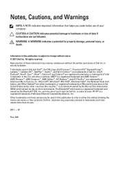
... (4 MB) Processor Processor type Total Cache • Intel Core i3 series • Intel Core i5 series up to view information about your computer, click Start (or Start in Windows XP) Help and Support, and then select the option to 8 MB cache depending on processor type Memory Type Speed Connectors Capacity Minimum Memory...
... (4 MB) Processor Processor type Total Cache • Intel Core i3 series • Intel Core i5 series up to view information about your computer, click Start (or Start in Windows XP) Help and Support, and then select the option to 8 MB cache depending on processor type Memory Type Speed Connectors Capacity Minimum Memory...
Owners Manual
Page 85
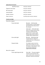
Solid amber light when the computer does not start indicates a problem with the system board. Blinking blue light indicates that the computer is functional. Green light - Blinking amber light indicates a problem with the system ... front panel of the computer. Amber light - Four lights located on and is reading data from or writing data to the power connector (at support.dell.com/manuals. Blue light - For more information on state; blinking blue light indicates sleep state of the computer: Power supply diagnostic light Blue light - The...
Solid amber light when the computer does not start indicates a problem with the system board. Blinking blue light indicates that the computer is functional. Green light - Blinking amber light indicates a problem with the system ... front panel of the computer. Amber light - Four lights located on and is reading data from or writing data to the power connector (at support.dell.com/manuals. Blue light - For more information on state; blinking blue light indicates sleep state of the computer: Power supply diagnostic light Blue light - The...


