User Manual
Page 1
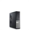
... Of Mini-Tower 1. optical drive bay 3. diagnostic lights (4) 6. Dell Optiplex 390 Setup And Features Information About Warnings WARNING: A WARNING indicates a potential for property damage, personal injury, or death. USB 2.0 connectors (2) 9. power-supply diagnostic button 12. microphone connector 5. headphone connector 4. optical drive 7. optical drive eject button 8. power cable connector Regulatory Model :D12M, D07D, D04S Regulatory Type...
... Of Mini-Tower 1. optical drive bay 3. diagnostic lights (4) 6. Dell Optiplex 390 Setup And Features Information About Warnings WARNING: A WARNING indicates a potential for property damage, personal injury, or death. USB 2.0 connectors (2) 9. power-supply diagnostic button 12. microphone connector 5. headphone connector 4. optical drive 7. optical drive eject button 8. power cable connector Regulatory Model :D12M, D07D, D04S Regulatory Type...
User Manual
Page 2
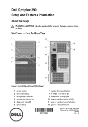
expansion card slots (4) Desktop - Front And Back View Of Desktop 1. power button 4. power cable connector 12. optical drive 2. headphone connector 7. diagnostic lights (4) 9. hard-drive activity light 8. power-supply diagnostic button 2 back panel connectors 14. Front And Back View 15. security cable slot 16. microphone connector 6. 13. padlock ring 10. expansion card slots (4) 14. power-supply diagnostic light 15. padlock ring Figure 2. optical drive eject button 3. back panel connectors 13. security cable slot 11. USB 2.0 connectors (2) 5.
expansion card slots (4) Desktop - Front And Back View Of Desktop 1. power button 4. power cable connector 12. optical drive 2. headphone connector 7. diagnostic lights (4) 9. hard-drive activity light 8. power-supply diagnostic button 2 back panel connectors 14. Front And Back View 15. security cable slot 16. microphone connector 6. 13. padlock ring 10. expansion card slots (4) 14. power-supply diagnostic light 15. padlock ring Figure 2. optical drive eject button 3. back panel connectors 13. security cable slot 11. USB 2.0 connectors (2) 5.
User Manual
Page 4
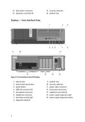
optical drive 2. USB 2.0 connectors (2) 5. headphone connector 7. hard-drive activity light 9. security cable slot 11. Front And Back View Of Small Form Factor 1. optical drive eject button 3. power-supply diagnostic light 14. Small Form Factor - power-supply diagnostic button 13. expansion card slots (2) 4 padlock ring 10. power cable connector 12. diagnostic lights (4) 8. back panel connectors 15. microphone connector 6. power button 4. Front And Back View Figure 4.
optical drive 2. USB 2.0 connectors (2) 5. headphone connector 7. hard-drive activity light 9. security cable slot 11. Front And Back View Of Small Form Factor 1. optical drive eject button 3. power-supply diagnostic light 14. Small Form Factor - power-supply diagnostic button 13. expansion card slots (2) 4 padlock ring 10. power cable connector 12. diagnostic lights (4) 8. back panel connectors 15. microphone connector 6. power button 4. Front And Back View Figure 4.
User Manual
Page 6
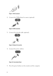
VGA Connector 2. Figure 8. Connect the network cable (optional). Figure 10. Figure 9. Network Connection 4. Figure 7. Press the power buttons on the monitor and the computer. 6 Connect the power cable(s). USB Connection 3. Connect the USB keyboard or mouse (optional). Connecting Power 5.
VGA Connector 2. Figure 8. Connect the network cable (optional). Figure 10. Figure 9. Network Connection 4. Figure 7. Press the power buttons on the monitor and the computer. 6 Connect the power cable(s). USB Connection 3. Connect the USB keyboard or mouse (optional). Connecting Power 5.

User Manual
Page 7
Power Button Specifications NOTE: The following specifications are only those required by law to support.dell.com. For a complete and current listing of the specifications for your computer. System Information Chipset Processor Intel H61 Express Chipset • Intel Core i3 Series &#...
Power Button Specifications NOTE: The following specifications are only those required by law to support.dell.com. For a complete and current listing of the specifications for your computer. System Information Chipset Processor Intel H61 Express Chipset • Intel Core i3 Series &#...
User Manual
Page 8
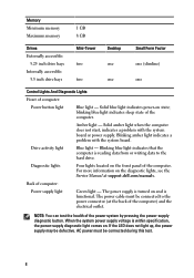
...Four lights located on the front panel of the power system by pressing the power-supply diagnostic button. NOTE: You can test the health of the computer. The power supply is reading data from or writing data to the power connector (at support.dell.com/manuals. If the LED does not light up..., the power supply may be connected during this test. 8 Back of the computer) and ...
...Four lights located on the front panel of the power system by pressing the power-supply diagnostic button. NOTE: You can test the health of the computer. The power supply is reading data from or writing data to the power connector (at support.dell.com/manuals. If the LED does not light up..., the power supply may be connected during this test. 8 Back of the computer) and ...
User Manual
Page 9
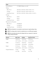
Power Coin-cell battery 3 V CR2032 lithium coin cell Voltage Mini-Tower 100 VAC to 240 VAC, 50 Hz to 60 ... BTU/hr Desktop 1312 BTU/hr Small Form Factor 1259 BTU/hr NOTE: Heat dissipation is available only on non-EPA power supplies. Physical Height Width Depth Weight (Minimum) Mini-Tower Desktop Small Form Factor 360.00 mm 360.00 mm 290.00...(19.55 lb) (16.67 lb) (12.57 lb) 9 NOTE: The voltage selector switch is calculated by using the power supply wattage rating. NOTE: See the safety information that shipped with your computer for important voltage-setting information.
Power Coin-cell battery 3 V CR2032 lithium coin cell Voltage Mini-Tower 100 VAC to 240 VAC, 50 Hz to 60 ... BTU/hr Desktop 1312 BTU/hr Small Form Factor 1259 BTU/hr NOTE: Heat dissipation is available only on non-EPA power supplies. Physical Height Width Depth Weight (Minimum) Mini-Tower Desktop Small Form Factor 360.00 mm 360.00 mm 290.00...(19.55 lb) (16.67 lb) (12.57 lb) 9 NOTE: The voltage selector switch is calculated by using the power supply wattage rating. NOTE: See the safety information that shipped with your computer for important voltage-setting information.
Technical Guide
Page 2
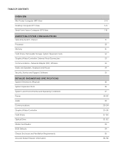
... and Speakers, Keyboard and Mouse Security, Service and Support, Software DETAILED ENGINEERING SPECIFICATIONS System Dimensions (Physical) System Expansion Slots System Level Environmental and Operating Conditions Power Audio Communications Graphics/Video Controller Hard Drives Optical Drive Media Card Reader BIOS Defaults Chassis Enclosure and Ventilation Requirements Acoustic Noise Emission Information 3-4 5-6 7-8 9 10 11...
... and Speakers, Keyboard and Mouse Security, Service and Support, Software DETAILED ENGINEERING SPECIFICATIONS System Dimensions (Physical) System Expansion Slots System Level Environmental and Operating Conditions Power Audio Communications Graphics/Video Controller Hard Drives Optical Drive Media Card Reader BIOS Defaults Chassis Enclosure and Ventilation Requirements Acoustic Noise Emission Information 3-4 5-6 7-8 9 10 11...
Technical Guide
Page 3
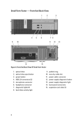
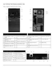
DELL™ OPTIPLEX™ 390 TECHNICAL GUIDEBOOK -FINAL MINI TOWER COMPUTER (MT) VIEW 1 6 10 7 11 15 2 12 16 8 3 4 9 5 13 14 FRONT VIEW BACK VIEW 1 Power Button, Power Light 6 Optical Drive (optional) 2 Optical Drive Bay (optional) 7 Optical Drive Eject Button 3 Microphone Connector 8 USB 2.0 Connectors (2) 4 Headphone Connector 9 Drive Activity Light 10 Power Supply Diagnostic 14 Expansion Card Slots(4) Light...
DELL™ OPTIPLEX™ 390 TECHNICAL GUIDEBOOK -FINAL MINI TOWER COMPUTER (MT) VIEW 1 6 10 7 11 15 2 12 16 8 3 4 9 5 13 14 FRONT VIEW BACK VIEW 1 Power Button, Power Light 6 Optical Drive (optional) 2 Optical Drive Bay (optional) 7 Optical Drive Eject Button 3 Microphone Connector 8 USB 2.0 Connectors (2) 4 Headphone Connector 9 Drive Activity Light 10 Power Supply Diagnostic 14 Expansion Card Slots(4) Light...
Technical Guide
Page 4
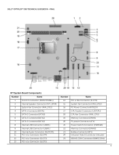
DELL™ OPTIPLEX™ 390 TECHNICAL GUIDEBOOK -FINAL MT System Board Components Number Name 1 Front IO connector (FRONTPANEL)) 2 Internal Speaker Connector (INT_SPKR) 3 System fan Connector (FAN_SYS1) 4 SATA 1 Connector(SATA1) 5 SATA...19 20 21 22 23 24 25 Name PCI-e 16x Connector (SLOT1) System fan Connector (FAN_SYS2) P2 Power Connector(ATX12V) CPU Socket Connector (U27CPU) CPU fan Connector (FAN_CPU) Memory Connector(DIMM1) P1 power Connector (ATX) Power Switch Connector (PWRSW1) Memory Connector(DIMM2) Battery Connector (BT1) Intrusion Switch Connector (Intruder) KB/MS COM...
DELL™ OPTIPLEX™ 390 TECHNICAL GUIDEBOOK -FINAL MT System Board Components Number Name 1 Front IO connector (FRONTPANEL)) 2 Internal Speaker Connector (INT_SPKR) 3 System fan Connector (FAN_SYS1) 4 SATA 1 Connector(SATA1) 5 SATA...19 20 21 22 23 24 25 Name PCI-e 16x Connector (SLOT1) System fan Connector (FAN_SYS2) P2 Power Connector(ATX12V) CPU Socket Connector (U27CPU) CPU fan Connector (FAN_CPU) Memory Connector(DIMM1) P1 power Connector (ATX) Power Switch Connector (PWRSW1) Memory Connector(DIMM2) Battery Connector (BT1) Intrusion Switch Connector (Intruder) KB/MS COM...
Technical Guide
Page 5
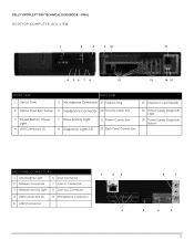
DELL™ OPTIPLEX™ 390 TECHNICAL GUIDEBOOK -FINAL DESKTOP COMPUTER (DT) VIEW 1 2 3 9 10 11 4 56 7 8 12 13 14 15 FRONT VIEW 1 Optical Drive BACK VIEW 5 Microphone Connector 9 Padlock Ring 13 Expansion Card Slots(4) 2 Optical Drive Eject Button 6 Headphone Connector 10 Security Cable Slot 3 Power Button, Power Light 4 USB Connectors (2) 7 Drive Activity Light 8 Diagnostic Lights (4) 11 Power Connectors...
DELL™ OPTIPLEX™ 390 TECHNICAL GUIDEBOOK -FINAL DESKTOP COMPUTER (DT) VIEW 1 2 3 9 10 11 4 56 7 8 12 13 14 15 FRONT VIEW 1 Optical Drive BACK VIEW 5 Microphone Connector 9 Padlock Ring 13 Expansion Card Slots(4) 2 Optical Drive Eject Button 6 Headphone Connector 10 Security Cable Slot 3 Power Button, Power Light 4 USB Connectors (2) 7 Drive Activity Light 8 Diagnostic Lights (4) 11 Power Connectors...
Technical Guide
Page 6
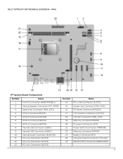
DELL™ OPTIPLEX™ 390 TECHNICAL GUIDEBOOK -FINAL DT System Board Components Number Name 1 Front IO connector (FRONTPANEL)) 2 Internal Speaker Connector (INT_SPKR) 3 System fan Connector (FAN_SYS1) 4 SATA 1 Connector(SATA1) 5 SATA...19 20 21 22 23 24 25 Name PCI-e 16x Connector (SLOT1) System fan Connector (FAN_SYS2) P2 Power Connector(ATX12V) CPU Socket Connector (U27CPU) CPU fan Connector (FAN_CPU) Memory Connector(DIMM1) P1 power Connector (ATX) Power Switch Connector (PWRSW1) Memory Connector(DIMM2) Battery Connector (BT1) Intrusion Switch Connector (Intruder) KB/MS COM...
DELL™ OPTIPLEX™ 390 TECHNICAL GUIDEBOOK -FINAL DT System Board Components Number Name 1 Front IO connector (FRONTPANEL)) 2 Internal Speaker Connector (INT_SPKR) 3 System fan Connector (FAN_SYS1) 4 SATA 1 Connector(SATA1) 5 SATA...19 20 21 22 23 24 25 Name PCI-e 16x Connector (SLOT1) System fan Connector (FAN_SYS2) P2 Power Connector(ATX12V) CPU Socket Connector (U27CPU) CPU fan Connector (FAN_CPU) Memory Connector(DIMM1) P1 power Connector (ATX) Power Switch Connector (PWRSW1) Memory Connector(DIMM2) Battery Connector (BT1) Intrusion Switch Connector (Intruder) KB/MS COM...
Technical Guide
Page 7
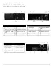
DELL™ OPTIPLEX™ 390 TECHNICAL GUIDEBOOK -FINAL SMALL FORM FACTOR COMPUTER (SFF) VIEW 1 2 3 9 10 11 12 13 4 56 7 8 14 15 FRONT VIEW 1 Optical Drive 5 Microphone Connector 2 Optical Drive Eject Button 6 Headphone Connector 3 Power Button, Power Light 4 USB 2.0 Connectors (2) 7 Diagnostic Lights (4) 8 Drive Activity Light BACK VIEW 9 Padlock Ring 10 Security Cable Slot 11 Power Connectors 13 Power... Supply Diagnostic Light 14 Back Panel Connectors 15 Expansion Card Slots(2) 12 Power Supply Diagnostic Button BACK ...
DELL™ OPTIPLEX™ 390 TECHNICAL GUIDEBOOK -FINAL SMALL FORM FACTOR COMPUTER (SFF) VIEW 1 2 3 9 10 11 12 13 4 56 7 8 14 15 FRONT VIEW 1 Optical Drive 5 Microphone Connector 2 Optical Drive Eject Button 6 Headphone Connector 3 Power Button, Power Light 4 USB 2.0 Connectors (2) 7 Diagnostic Lights (4) 8 Drive Activity Light BACK VIEW 9 Padlock Ring 10 Security Cable Slot 11 Power Connectors 13 Power... Supply Diagnostic Light 14 Back Panel Connectors 15 Expansion Card Slots(2) 12 Power Supply Diagnostic Button BACK ...
Technical Guide
Page 18
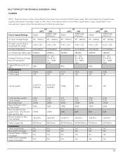
...DELL™ OPTIPLEX™ 390 TECHNICAL GUIDEBOOK -FINAL POWER NOTE: These form factors utilize a more than one 12v rail) BTUs/h (based on Sine Wave output for APFC PSUs, not an approximation of a Sine Wave, Square Wave, or quasi-Square Wave. Dell recommends only Universal Power Supplies (UPS) based on PSU max wattage) Power... Supply Fan Compliance: 1watt requirement Blue Angel Compliant Climate Savers / 80Plus Compliant FEMP (CECP) Standby Power Compliant 4.0A 0.5A 265W 90W...
...DELL™ OPTIPLEX™ 390 TECHNICAL GUIDEBOOK -FINAL POWER NOTE: These form factors utilize a more than one 12v rail) BTUs/h (based on Sine Wave output for APFC PSUs, not an approximation of a Sine Wave, Square Wave, or quasi-Square Wave. Dell recommends only Universal Power Supplies (UPS) based on PSU max wattage) Power... Supply Fan Compliance: 1watt requirement Blue Angel Compliant Climate Savers / 80Plus Compliant FEMP (CECP) Standby Power Compliant 4.0A 0.5A 265W 90W...
Technical Guide
Page 19
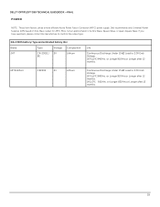
... Lithium Continuous Discharge Under 15 kΩ Load to 2.0V EndVoltage. 20℃±2℃.940Hrs. DELL™ OPTIPLEX™ 390 TECHNICAL GUIDEBOOK -FINAL POWER NOTE: These form factors utilize a more efficient Active Power Factor Correction (APFC) power supply. Dell recommends only Universal Power Supplies (UPS) based on Sine Wave output for APFC PSUs, not an approximation of a Sine...
... Lithium Continuous Discharge Under 15 kΩ Load to 2.0V EndVoltage. 20℃±2℃.940Hrs. DELL™ OPTIPLEX™ 390 TECHNICAL GUIDEBOOK -FINAL POWER NOTE: These form factors utilize a more efficient Active Power Factor Correction (APFC) power supply. Dell recommends only Universal Power Supplies (UPS) based on Sine Wave output for APFC PSUs, not an approximation of a Sine...
Technical Guide
Page 20
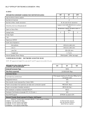
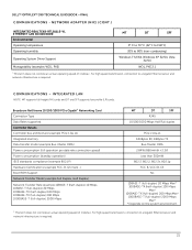
...) 200 Mbps 1000BASE-T (full-duplex) 2000 Mbps MT DT SFF RJ45 10/100/1000 Mbps PCIe-based interface for S0 state, SMBus for Sx low power state N/A N/A 448.8mW (Max.) 389.4mW (Max.) 802.3 N/A EEPROM (located in SPI) 10 Mb (full/half-duplex) 100 Mb (full/half-...duplex) 20 NETWORK ADAPTER (NIC) NOTE: MT supports full height (FH) cards and DT and SFF supports low profile (LP) cards. DELL™ OPTIPLEX™ 390 TECHNICAL GUIDEBOOK -FINAL AUDIO INTEGRATED CONEXANT CX20641 HIGH DEFINITION AUDIO High Definition Stereo support Number of channels Number of Bits / Audio resolution Sampling rate...
...) 200 Mbps 1000BASE-T (full-duplex) 2000 Mbps MT DT SFF RJ45 10/100/1000 Mbps PCIe-based interface for S0 state, SMBus for Sx low power state N/A N/A 448.8mW (Max.) 389.4mW (Max.) 802.3 N/A EEPROM (located in SPI) 10 Mb (full/half-duplex) 100 Mb (full/half-...duplex) 20 NETWORK ADAPTER (NIC) NOTE: MT supports full height (FH) cards and DT and SFF supports low profile (LP) cards. DELL™ OPTIPLEX™ 390 TECHNICAL GUIDEBOOK -FINAL AUDIO INTEGRATED CONEXANT CX20641 HIGH DEFINITION AUDIO High Definition Stereo support Number of channels Number of Bits / Audio resolution Sampling rate...
Technical Guide
Page 21
...bus architecture (example PCIe 1.0a x1) Integrated memory Data transfer mode (example Bus-Master DMA) Power consumption (full operation per data rate connection speed) Power consumption (standby operation) IEEE standards compliance (example 802.1P) Hardware Certifications (example FCC, B, ...* Depends on the system environment. 1 This term does not connote an actual operating speed of 1 Gb/sec. COMMUNICATIONS - DELL™ OPTIPLEX™ 390 TECHNICAL GUIDEBOOK -FINAL COMMUNICATIONS - NETWORK ADAPTER (NIC) (CONT.) INTEGRATED REALTEK® RTL8111E-VL ETHERNET LAN 10/100/1000 Environmental...
...bus architecture (example PCIe 1.0a x1) Integrated memory Data transfer mode (example Bus-Master DMA) Power consumption (full operation per data rate connection speed) Power consumption (standby operation) IEEE standards compliance (example 802.1P) Hardware Certifications (example FCC, B, ...* Depends on the system environment. 1 This term does not connote an actual operating speed of 1 Gb/sec. COMMUNICATIONS - DELL™ OPTIPLEX™ 390 TECHNICAL GUIDEBOOK -FINAL COMMUNICATIONS - NETWORK ADAPTER (NIC) (CONT.) INTEGRATED REALTEK® RTL8111E-VL ETHERNET LAN 10/100/1000 Environmental...
Technical Guide
Page 23
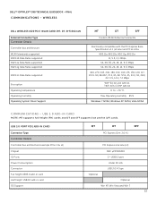
...cards. USB 3.0 PORT PCIE ADD-IN CARD Connector Type Controller Details Controller bus architecture (example PCIe 1.0a x1) Chipset IO Ports Power Consumption Connector Full height USB3.0 add-in card Half height USB3.0 add-in card OS Support MT DT SFF PCI Express Gen. 2.0... 2 * USB3.0 port Under 30 mA USB 3.0 A Type Optional Optional Win XP, Win Vista and Win 7 23 DELL™ OPTIPLEX™ 390 TECHNICAL GUIDEBOOK -FINAL COMMUNICATIONS - WIRELESS DELL WIRELESS 1520 PCIE WLAN CARD (MT, DT, SFF) 802.11N External Connector Type Controller Details Controller bus architecture WLAN standards ...
...cards. USB 3.0 PORT PCIE ADD-IN CARD Connector Type Controller Details Controller bus architecture (example PCIe 1.0a x1) Chipset IO Ports Power Consumption Connector Full height USB3.0 add-in card Half height USB3.0 add-in card OS Support MT DT SFF PCI Express Gen. 2.0... 2 * USB3.0 port Under 30 mA USB 3.0 A Type Optional Optional Win XP, Win Vista and Win 7 23 DELL™ OPTIPLEX™ 390 TECHNICAL GUIDEBOOK -FINAL COMMUNICATIONS - WIRELESS DELL WIRELESS 1520 PCIE WLAN CARD (MT, DT, SFF) 802.11N External Connector Type Controller Details Controller bus architecture WLAN standards ...
Technical Guide
Page 25
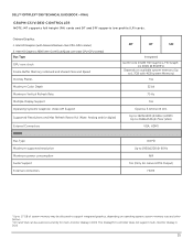
... digital) External Connectors HDMI Bus Type Maximum supported resolution Maximum power consumption Audio Support External connectors MT DT SFF Integrated Gen6 Core Intel® HD Graphics /HD Graph- The DisplayPort controller does not support multi-monitor display in DOS. DELL™ OPTIPLEX™ 390 TECHNICAL GUIDEBOOK -FINAL GRAPHICS/VIDEO CONTROLLER NOTE: MT supports full...
... digital) External Connectors HDMI Bus Type Maximum supported resolution Maximum power consumption Audio Support External connectors MT DT SFF Integrated Gen6 Core Intel® HD Graphics /HD Graph- The DisplayPort controller does not support multi-monitor display in DOS. DELL™ OPTIPLEX™ 390 TECHNICAL GUIDEBOOK -FINAL GRAPHICS/VIDEO CONTROLLER NOTE: MT supports full...
Technical Guide
Page 26
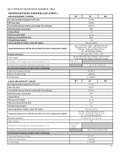
... 2.731 / 16.764 x 6.936 No 6.6 x 2.731 / 16.764 x 6.936 10°-50° C 5-90% RH 0-20,000 ft. 26 DELL™ OPTIPLEX™ 390 TECHNICAL GUIDEBOOK -FINAL GRAPHICS/VIDEO CONTROLLER (CONT.) 1GB AMD RADEON™ HD6450 Bus Type (example integrated or PCIe x16) GPU core clock Frame Buffer... Bus Type (example integrated or PCIe x16) GPU core clock Frame Buffer Memory (onboard and shared) Size and Speed Maximum power consumption Overlay Planes Maximum Color Depth Maximum Vertical Refresh Rate Multiple Display Support Operating Systems Graphics/ Video API Support Supported Resolutions and...
... 2.731 / 16.764 x 6.936 No 6.6 x 2.731 / 16.764 x 6.936 10°-50° C 5-90% RH 0-20,000 ft. 26 DELL™ OPTIPLEX™ 390 TECHNICAL GUIDEBOOK -FINAL GRAPHICS/VIDEO CONTROLLER (CONT.) 1GB AMD RADEON™ HD6450 Bus Type (example integrated or PCIe x16) GPU core clock Frame Buffer... Bus Type (example integrated or PCIe x16) GPU core clock Frame Buffer Memory (onboard and shared) Size and Speed Maximum power consumption Overlay Planes Maximum Color Depth Maximum Vertical Refresh Rate Multiple Display Support Operating Systems Graphics/ Video API Support Supported Resolutions and...


