User Manual
Page 1
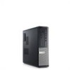
Front And Back View Of Mini-Tower 1. optical drive eject button 8. power cable connector Regulatory Model :D12M, D07D, D04S Regulatory Type :D12M001, D07D001, D04S001 2011 - 05 Mini-Tower - optical drive bay 3. microphone connector 5. Dell Optiplex 390 Setup And Features Information About Warnings WARNING: A WARNING indicates a potential for property damage, personal injury, or death. diagnostic lights (4) 6. hard-drive...
Front And Back View Of Mini-Tower 1. optical drive eject button 8. power cable connector Regulatory Model :D12M, D07D, D04S Regulatory Type :D12M001, D07D001, D04S001 2011 - 05 Mini-Tower - optical drive bay 3. microphone connector 5. Dell Optiplex 390 Setup And Features Information About Warnings WARNING: A WARNING indicates a potential for property damage, personal injury, or death. diagnostic lights (4) 6. hard-drive...
User Manual
Page 2
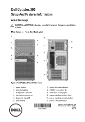
13. security cable slot 16. optical drive 2. power button 4. headphone connector 7. padlock ring 10. power-supply diagnostic button 2 expansion card slots (4) Desktop - Front And Back View Of Desktop 1. optical drive eject button 3. security cable slot 11. back panel connectors 14. diagnostic lights (4) 9. expansion card slots (4) 14. microphone connector 6. hard-drive activity light 8. power cable connector 12. Front And Back View 15. padlock ring Figure 2. USB 2.0 connectors (2) 5. back panel connectors 13. power-supply diagnostic light 15.
13. security cable slot 16. optical drive 2. power button 4. headphone connector 7. padlock ring 10. power-supply diagnostic button 2 expansion card slots (4) Desktop - Front And Back View Of Desktop 1. optical drive eject button 3. security cable slot 11. back panel connectors 14. diagnostic lights (4) 9. expansion card slots (4) 14. microphone connector 6. hard-drive activity light 8. power cable connector 12. Front And Back View 15. padlock ring Figure 2. USB 2.0 connectors (2) 5. back panel connectors 13. power-supply diagnostic light 15.
User Manual
Page 4
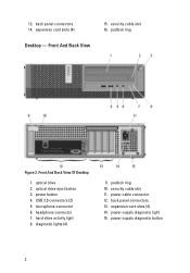
Front And Back View Of Small Form Factor 1. USB 2.0 connectors (2) 5. headphone connector 7. security cable slot 11. power-supply diagnostic light 14. optical drive 2. optical drive eject button 3. back panel connectors 15. hard-drive activity light 9. power-supply diagnostic button 13. diagnostic lights (4) 8. microphone connector 6. power cable connector 12. Front And Back View Figure 4. padlock ring 10. expansion card slots (2) 4 power button 4. Small Form Factor -
Front And Back View Of Small Form Factor 1. USB 2.0 connectors (2) 5. headphone connector 7. security cable slot 11. power-supply diagnostic light 14. optical drive 2. optical drive eject button 3. back panel connectors 15. hard-drive activity light 9. power-supply diagnostic button 13. diagnostic lights (4) 8. microphone connector 6. power cable connector 12. Front And Back View Figure 4. padlock ring 10. expansion card slots (2) 4 power button 4. Small Form Factor -
User Manual
Page 6
Network Connection 4. Connect the power cable(s). Connecting Power 5. Figure 7. Connect the USB keyboard or mouse (optional). Figure 8. USB Connection 3. Figure 9. Figure 10. Connect the network cable (optional). VGA Connector 2. Press the power buttons on the monitor and the computer. 6
Network Connection 4. Connect the power cable(s). Connecting Power 5. Figure 7. Connect the USB keyboard or mouse (optional). Figure 8. USB Connection 3. Figure 9. Figure 10. Connect the network cable (optional). VGA Connector 2. Press the power buttons on the monitor and the computer. 6

User Manual
Page 7
Figure 11. For a complete and current listing of the specifications for your computer. Power Button Specifications NOTE: The following specifications are only those required by law to support.dell.com. System Information Chipset Processor Intel H61 Express Chipset • Intel Core i3 Series • Intel Core i5 Series ...AMD Radeon HD 6450 up to 1.7 GB shared video memory (Microsoft Windows Vista and Windows 7) up to 1 GB Memory Memory module connector Memory module capacity Memory type two DIMM slots 1 GB, 2 GB, and 4 GB DDR3 with your computer, go to ship with 1333 MHz 7
Figure 11. For a complete and current listing of the specifications for your computer. Power Button Specifications NOTE: The following specifications are only those required by law to support.dell.com. System Information Chipset Processor Intel H61 Express Chipset • Intel Core i3 Series • Intel Core i5 Series ...AMD Radeon HD 6450 up to 1.7 GB shared video memory (Microsoft Windows Vista and Windows 7) up to 1 GB Memory Memory module connector Memory module capacity Memory type two DIMM slots 1 GB, 2 GB, and 4 GB DDR3 with your computer, go to ship with 1333 MHz 7
User Manual
Page 8
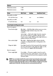
... a problem with the system board. blinking blue light indicates sleep state of the power system by pressing the power-supply diagnostic button. The power supply is reading data from or writing data to the power connector (at support.dell.com/manuals. The power cable must be defective. For more information on the diagnostic lights, see the Service...
... a problem with the system board. blinking blue light indicates sleep state of the power system by pressing the power-supply diagnostic button. The power supply is reading data from or writing data to the power connector (at support.dell.com/manuals. The power cable must be defective. For more information on the diagnostic lights, see the Service...
Technical Guide
Page 2
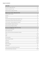
...Operating System, Chipset Processor Memory Hard Drives, Removable Storage, System Expansion Slots Graphics/Video Controller, External Ports/Connectors Communications-Network Adapter (NIC), Wireless Audio and Speakers, Keyboard and Mouse Security, Service and Support, Software ...DETAILED ENGINEERING SPECIFICATIONS System Dimensions (Physical) System Expansion Slots System Level Environmental and Operating Conditions Power Audio Communications Graphics/Video Controller Hard Drives Optical Drive Media Card Reader BIOS Defaults Chassis Enclosure and Ventilation Requirements...
...Operating System, Chipset Processor Memory Hard Drives, Removable Storage, System Expansion Slots Graphics/Video Controller, External Ports/Connectors Communications-Network Adapter (NIC), Wireless Audio and Speakers, Keyboard and Mouse Security, Service and Support, Software ...DETAILED ENGINEERING SPECIFICATIONS System Dimensions (Physical) System Expansion Slots System Level Environmental and Operating Conditions Power Audio Communications Graphics/Video Controller Hard Drives Optical Drive Media Card Reader BIOS Defaults Chassis Enclosure and Ventilation Requirements...
Technical Guide
Page 3
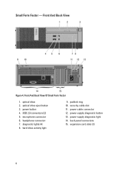
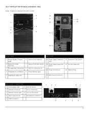
DELL™ OPTIPLEX™ 390 TECHNICAL GUIDEBOOK -FINAL MINI TOWER COMPUTER (MT) VIEW 1 6 10 7 11 15 2 12 16 8 3 4 9 5 13 14 FRONT VIEW BACK VIEW 1 Power Button, Power Light 6 Optical Drive (optional) 2 Optical Drive Bay (optional) 7 Optical Drive Eject Button 3 Microphone Connector 8 USB 2.0 Connectors (2) 4 Headphone Connector 9 Drive Activity Light 10 Power Supply Diagnostic 14 Expansion Card Slots(4) Light 11 Power Supply Diagnostic...
DELL™ OPTIPLEX™ 390 TECHNICAL GUIDEBOOK -FINAL MINI TOWER COMPUTER (MT) VIEW 1 6 10 7 11 15 2 12 16 8 3 4 9 5 13 14 FRONT VIEW BACK VIEW 1 Power Button, Power Light 6 Optical Drive (optional) 2 Optical Drive Bay (optional) 7 Optical Drive Eject Button 3 Microphone Connector 8 USB 2.0 Connectors (2) 4 Headphone Connector 9 Drive Activity Light 10 Power Supply Diagnostic 14 Expansion Card Slots(4) Light 11 Power Supply Diagnostic...
Technical Guide
Page 4
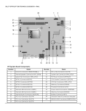
DELL™ OPTIPLEX™ 390 TECHNICAL GUIDEBOOK -FINAL MT System Board Components Number Name 1 Front IO connector (FRONTPANEL)) 2 Internal Speaker Connector (INT_SPKR) 3 System fan Connector (FAN_SYS1) 4 SATA 1 Connector(SATA1) 5 SATA 0 Connector(SATA0) 6 SATA 2 Connector(SATA2) 7 SATA 3 Connector(SATA3) 8 Internal USB Connector (USBF1) 9 Internal USB Connector (USBF1) 10 Internal Audio Connector (AUDIOF1) 11 PCI-e 1x Connector (SLOT4) 12 PCI-e 1x Connector (SLOT3) 13 PCI-e 1x Connector (SLOT2) Number...
DELL™ OPTIPLEX™ 390 TECHNICAL GUIDEBOOK -FINAL MT System Board Components Number Name 1 Front IO connector (FRONTPANEL)) 2 Internal Speaker Connector (INT_SPKR) 3 System fan Connector (FAN_SYS1) 4 SATA 1 Connector(SATA1) 5 SATA 0 Connector(SATA0) 6 SATA 2 Connector(SATA2) 7 SATA 3 Connector(SATA3) 8 Internal USB Connector (USBF1) 9 Internal USB Connector (USBF1) 10 Internal Audio Connector (AUDIOF1) 11 PCI-e 1x Connector (SLOT4) 12 PCI-e 1x Connector (SLOT3) 13 PCI-e 1x Connector (SLOT2) Number...
Technical Guide
Page 5
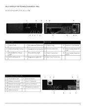
DELL™ OPTIPLEX™ 390 TECHNICAL GUIDEBOOK -FINAL DESKTOP COMPUTER (DT) VIEW 1 2 3 9 10 11 4 56 7 8 12 13 14 15 FRONT VIEW 1 Optical Drive BACK VIEW 5 Microphone Connector 9 Padlock Ring 13 Expansion Card Slots(4) 2 Optical Drive Eject Button 6 Headphone Connector 10 Security Cable Slot 3 Power Button, Power Light 4 USB Connectors (2) 7 Drive Activity Light 8 Diagnostic Lights (4) 11 Power Connectors 12 Back Panel Connectors 14...
DELL™ OPTIPLEX™ 390 TECHNICAL GUIDEBOOK -FINAL DESKTOP COMPUTER (DT) VIEW 1 2 3 9 10 11 4 56 7 8 12 13 14 15 FRONT VIEW 1 Optical Drive BACK VIEW 5 Microphone Connector 9 Padlock Ring 13 Expansion Card Slots(4) 2 Optical Drive Eject Button 6 Headphone Connector 10 Security Cable Slot 3 Power Button, Power Light 4 USB Connectors (2) 7 Drive Activity Light 8 Diagnostic Lights (4) 11 Power Connectors 12 Back Panel Connectors 14...
Technical Guide
Page 6
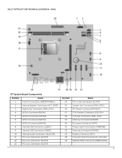
DELL™ OPTIPLEX™ 390 TECHNICAL GUIDEBOOK -FINAL DT System Board Components Number Name 1 Front IO connector (FRONTPANEL)) 2 Internal Speaker Connector (INT_SPKR) 3 System fan Connector (FAN_SYS1) 4 SATA 1 Connector(SATA1) 5 SATA 0 Connector(SATA0) 6 SATA 2 Connector(SATA2) 7 SATA 3 Connector(SATA3) 8 Internal USB Connector (USBF1) 9 Internal USB Connector (USBF1) 10 Internal Audio Connector (AUDIOF1) 11 PCI-e 1x Connector (SLOT4) 12 PCI-e 1x Connector (SLOT3) 13 PCI-e 1x Connector (SLOT2) Number...
DELL™ OPTIPLEX™ 390 TECHNICAL GUIDEBOOK -FINAL DT System Board Components Number Name 1 Front IO connector (FRONTPANEL)) 2 Internal Speaker Connector (INT_SPKR) 3 System fan Connector (FAN_SYS1) 4 SATA 1 Connector(SATA1) 5 SATA 0 Connector(SATA0) 6 SATA 2 Connector(SATA2) 7 SATA 3 Connector(SATA3) 8 Internal USB Connector (USBF1) 9 Internal USB Connector (USBF1) 10 Internal Audio Connector (AUDIOF1) 11 PCI-e 1x Connector (SLOT4) 12 PCI-e 1x Connector (SLOT3) 13 PCI-e 1x Connector (SLOT2) Number...
Technical Guide
Page 7
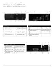
DELL™ OPTIPLEX™ 390 TECHNICAL GUIDEBOOK -FINAL SMALL FORM FACTOR COMPUTER (SFF) VIEW 1 2 3 9 10 11 12 13 4 56 7 8 14 15 FRONT VIEW 1 Optical Drive 5 Microphone Connector 2 Optical Drive Eject Button 6 Headphone Connector 3 Power Button, Power Light 4 USB 2.0 Connectors (2) 7 Diagnostic Lights (4) 8 Drive Activity Light BACK VIEW 9 Padlock Ring 10 Security Cable Slot 11 Power Connectors 13 Power Supply Diagnostic Light 14 Back...
DELL™ OPTIPLEX™ 390 TECHNICAL GUIDEBOOK -FINAL SMALL FORM FACTOR COMPUTER (SFF) VIEW 1 2 3 9 10 11 12 13 4 56 7 8 14 15 FRONT VIEW 1 Optical Drive 5 Microphone Connector 2 Optical Drive Eject Button 6 Headphone Connector 3 Power Button, Power Light 4 USB 2.0 Connectors (2) 7 Diagnostic Lights (4) 8 Drive Activity Light BACK VIEW 9 Padlock Ring 10 Security Cable Slot 11 Power Connectors 13 Power Supply Diagnostic Light 14 Back...
Technical Guide
Page 20
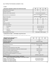
...RTL8111E-VL ETHERNET LAN 10/100/1000 External Connector Type Data Rates supported Controller Details Controller bus architecture Integrated memory Data transfer mode (example Bus-Master DMA) Power consumption (full operation per data rate connection speed) Power consumption (standby operation) IEEE standards compliance (... (NIC) NOTE: MT supports full height (FH) cards and DT and SFF supports low profile (LP) cards. DELL™ OPTIPLEX™ 390 TECHNICAL GUIDEBOOK -FINAL AUDIO INTEGRATED CONEXANT CX20641 HIGH DEFINITION AUDIO High Definition Stereo support Number of channels Number of Bits /...
...RTL8111E-VL ETHERNET LAN 10/100/1000 External Connector Type Data Rates supported Controller Details Controller bus architecture Integrated memory Data transfer mode (example Bus-Master DMA) Power consumption (full operation per data rate connection speed) Power consumption (standby operation) IEEE standards compliance (... (NIC) NOTE: MT supports full height (FH) cards and DT and SFF supports low profile (LP) cards. DELL™ OPTIPLEX™ 390 TECHNICAL GUIDEBOOK -FINAL AUDIO INTEGRATED CONEXANT CX20641 HIGH DEFINITION AUDIO High Definition Stereo support Number of channels Number of Bits /...
Technical Guide
Page 21
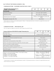
... to a Gigabit Ethernet server and network infrastructure is required. DELL™ OPTIPLEX™ 390 TECHNICAL GUIDEBOOK -FINAL COMMUNICATIONS - NETWORK ADAPTER (NIC) (CONT...of 1 Gb/sec. Broadcom NetXtreme 10/100/1000 PCIe Gigabit1 Networking Card Connector Type Data Rates supported Controller Details Controller bus architecture (example PCIe 1.0a x1) Integrated memory ...Data transfer mode (example Bus-Master DMA) Power consumption (full operation per data rate connection speed) Power consumption (standby operation) IEEE standards compliance (example 802.1P) Hardware ...
... to a Gigabit Ethernet server and network infrastructure is required. DELL™ OPTIPLEX™ 390 TECHNICAL GUIDEBOOK -FINAL COMMUNICATIONS - NETWORK ADAPTER (NIC) (CONT...of 1 Gb/sec. Broadcom NetXtreme 10/100/1000 PCIe Gigabit1 Networking Card Connector Type Data Rates supported Controller Details Controller bus architecture (example PCIe 1.0a x1) Integrated memory ...Data transfer mode (example Bus-Master DMA) Power consumption (full operation per data rate connection speed) Power consumption (standby operation) IEEE standards compliance (example 802.1P) Hardware ...
Technical Guide
Page 23
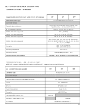
DELL™ OPTIPLEX™ 390 TECHNICAL GUIDEBOOK -FINAL COMMUNICATIONS - USB 3.0 PORT PCIE ADD-IN CARD Connector Type Controller Details Controller bus architecture (example PCIe 1.0a x1) Chipset IO Ports Power Consumption Connector Full height USB3.0 add-in card Half height USB3.0 add-in card OS Support MT DT SFF PCI Express Gen. 2.0 X1 PCI Express one lane...
DELL™ OPTIPLEX™ 390 TECHNICAL GUIDEBOOK -FINAL COMMUNICATIONS - USB 3.0 PORT PCIE ADD-IN CARD Connector Type Controller Details Controller bus architecture (example PCIe 1.0a x1) Chipset IO Ports Power Consumption Connector Full height USB3.0 add-in card Half height USB3.0 add-in card OS Support MT DT SFF PCI Express Gen. 2.0 X1 PCI Express one lane...
Technical Guide
Page 25
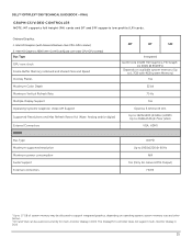
... Resolutions and Max Refresh Rates (Hz) (Note: Analog and/or digital) External Connectors HDMI Bus Type Maximum supported resolution Maximum power consumption Audio Support External connectors MT DT SFF Integrated Gen6 Core Intel® HD Graphics /HD Graph- DELL™ OPTIPLEX™ 390 TECHNICAL GUIDEBOOK -FINAL GRAPHICS/VIDEO CONTROLLER NOTE: MT supports full height (FH) cards...
... Resolutions and Max Refresh Rates (Hz) (Note: Analog and/or digital) External Connectors HDMI Bus Type Maximum supported resolution Maximum power consumption Audio Support External connectors MT DT SFF Integrated Gen6 Core Intel® HD Graphics /HD Graph- DELL™ OPTIPLEX™ 390 TECHNICAL GUIDEBOOK -FINAL GRAPHICS/VIDEO CONTROLLER NOTE: MT supports full height (FH) cards...
Technical Guide
Page 26
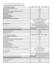
.... 6.6 x 4.7 / 16.764 x 12.0 6.6 x 3.35 / 16.764 x 8.5 10°-50° C 5-90% RH 0-20,000 ft. DELL™ OPTIPLEX™ 390 TECHNICAL GUIDEBOOK -FINAL GRAPHICS/VIDEO CONTROLLER (CONT.) 1GB AMD RADEON™ HD6450 Bus Type (example integrated or PCIe x16) GPU core clock Frame Buffer...) Size and Speed Maximum power consumption Overlay Planes Maximum Color Depth Maximum Vertical Refresh Rate Multiple Display Support Operating Systems Graphics/ Video API Support Supported Resolutions and Max Refresh Rates (Hz) (Note: Analog and/or digital) External connectors Audio Support Dimensions of full...
.... 6.6 x 4.7 / 16.764 x 12.0 6.6 x 3.35 / 16.764 x 8.5 10°-50° C 5-90% RH 0-20,000 ft. DELL™ OPTIPLEX™ 390 TECHNICAL GUIDEBOOK -FINAL GRAPHICS/VIDEO CONTROLLER (CONT.) 1GB AMD RADEON™ HD6450 Bus Type (example integrated or PCIe x16) GPU core clock Frame Buffer...) Size and Speed Maximum power consumption Overlay Planes Maximum Color Depth Maximum Vertical Refresh Rate Multiple Display Support Operating Systems Graphics/ Video API Support Supported Resolutions and Max Refresh Rates (Hz) (Note: Analog and/or digital) External connectors Audio Support Dimensions of full...

Owners Manual
Page 67
... pre-POST and POST LEDs in the power connector at the back of the chassis next to the power button. This has no longer visible. These diagnostic LEDs are located on Self-Test (POST) process. Diagnostic Light Patterns LED Power Button Problem Description Troubleshooting Steps The computer ... a possible problem with another device, such as an indicator of the progress through the Power-on the front of the computer and the electrical outlet. • Bypass power strips, power extension cables, and other significance. These LEDs do not indicate the problem that the electrical...
... pre-POST and POST LEDs in the power connector at the back of the chassis next to the power button. This has no longer visible. These diagnostic LEDs are located on Self-Test (POST) process. Diagnostic Light Patterns LED Power Button Problem Description Troubleshooting Steps The computer ... a possible problem with another device, such as an indicator of the progress through the Power-on the front of the computer and the electrical outlet. • Bypass power strips, power extension cables, and other significance. These LEDs do not indicate the problem that the electrical...

Owners Manual
Page 70
... add the peripheral cards back one by one until you find the bad one . Troubleshooting Steps Re-seat the 2x2 power connector from the PCI and PCI-E slots and re-start the computer. LED Power Button Problem Description Troubleshooting Steps A possible system board failure has occurred. • Disconnect all peripheral cards from the...
... add the peripheral cards back one by one until you find the bad one . Troubleshooting Steps Re-seat the 2x2 power connector from the PCI and PCI-E slots and re-start the computer. LED Power Button Problem Description Troubleshooting Steps A possible system board failure has occurred. • Disconnect all peripheral cards from the...
Owners Manual
Page 85
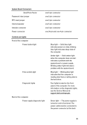
... on and is reading data from or writing data to the power connector (at support.dell.com/manuals. Blinking blue light indicates that the computer is functional. Solid amber light when the computer does not start indicates a problem with the system board. The power cable must be connected to the hard drive. Green light...
... on and is reading data from or writing data to the power connector (at support.dell.com/manuals. Blinking blue light indicates that the computer is functional. Solid amber light when the computer does not start indicates a problem with the system board. The power cable must be connected to the hard drive. Green light...


