User Manual
Page 1
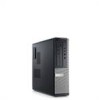
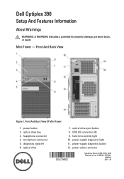
optical drive eject button 8. hard-drive activity light 10. Front And Back View Of Mini-Tower 1. Mini-Tower - microphone connector 5. power-supply diagnostic light 11. power-supply diagnostic button 12. diagnostic lights (4) 6. power button 2. headphone connector 4. optical drive 7. Front And Back View Figure 1. Dell Optiplex 390 Setup And Features Information About Warnings WARNING: A WARNING indicates a potential for property...
optical drive eject button 8. hard-drive activity light 10. Front And Back View Of Mini-Tower 1. Mini-Tower - microphone connector 5. power-supply diagnostic light 11. power-supply diagnostic button 12. diagnostic lights (4) 6. power button 2. headphone connector 4. optical drive 7. Front And Back View Figure 1. Dell Optiplex 390 Setup And Features Information About Warnings WARNING: A WARNING indicates a potential for property...
User Manual
Page 2
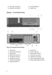
Front And Back View 15. padlock ring Figure 2. padlock ring 10. power cable connector 12. power-supply diagnostic light 15. power button 4. hard-drive activity light 8. power-supply diagnostic button 2 security cable slot 16. Front And Back View Of Desktop 1. USB 2.0 connectors (2) 5. microphone connector 6. optical drive eject button 3. expansion card slots (4) Desktop - 13. headphone connector 7. back panel connectors 13. security cable slot 11. diagnostic lights (4) 9. back panel connectors 14. optical drive 2. expansion card slots (4) 14.
Front And Back View 15. padlock ring Figure 2. padlock ring 10. power cable connector 12. power-supply diagnostic light 15. power button 4. hard-drive activity light 8. power-supply diagnostic button 2 security cable slot 16. Front And Back View Of Desktop 1. USB 2.0 connectors (2) 5. microphone connector 6. optical drive eject button 3. expansion card slots (4) Desktop - 13. headphone connector 7. back panel connectors 13. security cable slot 11. diagnostic lights (4) 9. back panel connectors 14. optical drive 2. expansion card slots (4) 14.
User Manual
Page 4
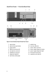
Front And Back View Figure 4. optical drive 2. diagnostic lights (4) 8. hard-drive activity light 9. security cable slot 11. back panel connectors 15. USB 2.0 connectors (2) 5. power cable connector 12. power button 4. padlock ring 10. optical drive eject button 3. Front And Back View Of Small Form Factor 1. power-supply diagnostic light 14. headphone connector 7. power-supply diagnostic button 13. Small Form Factor - microphone connector 6. expansion card slots (2) 4
Front And Back View Figure 4. optical drive 2. diagnostic lights (4) 8. hard-drive activity light 9. security cable slot 11. back panel connectors 15. USB 2.0 connectors (2) 5. power cable connector 12. power button 4. padlock ring 10. optical drive eject button 3. Front And Back View Of Small Form Factor 1. power-supply diagnostic light 14. headphone connector 7. power-supply diagnostic button 13. Small Form Factor - microphone connector 6. expansion card slots (2) 4
User Manual
Page 8
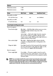
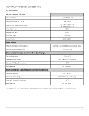
...The power cable must be defective. Memory Minimum memory Maximum memory 1 GB 8 GB Drives Externally accessible: 5.25 inch drive bays Internally accessible: 3.5 inch drive bays Mini-Tower two two Desktop one one Small Form Factor one (slimline) one Control...dell.com/manuals. Back of the computer. Blinking blue light indicates that the computer is within specification, the power-supply diagnostic light comes on state; Diagnostic lights Four lights located on the front panel of computer: Power supply light Green light - AC power must be connected to the hard drive...
...The power cable must be defective. Memory Minimum memory Maximum memory 1 GB 8 GB Drives Externally accessible: 5.25 inch drive bays Internally accessible: 3.5 inch drive bays Mini-Tower two two Desktop one one Small Form Factor one (slimline) one Control...dell.com/manuals. Back of the computer. Blinking blue light indicates that the computer is within specification, the power-supply diagnostic light comes on state; Diagnostic lights Four lights located on the front panel of computer: Power supply light Green light - AC power must be connected to the hard drive...
Technical Guide
Page 2
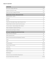
...Computer (DT) View Small Form Factor Computer (SFF) View MARKETING SYSTEM CONFIGURATIONS Operating System, Chipset Processor Memory Hard Drives, Removable Storage, System Expansion Slots Graphics/Video Controller, External Ports/Connectors Communications-Network Adapter (NIC), Wireless Audio... Dimensions (Physical) System Expansion Slots System Level Environmental and Operating Conditions Power Audio Communications Graphics/Video Controller Hard Drives Optical Drive Media Card Reader BIOS Defaults Chassis Enclosure and Ventilation Requirements Acoustic Noise Emission Information 3-4 5-6 7-8 9 ...
...Computer (DT) View Small Form Factor Computer (SFF) View MARKETING SYSTEM CONFIGURATIONS Operating System, Chipset Processor Memory Hard Drives, Removable Storage, System Expansion Slots Graphics/Video Controller, External Ports/Connectors Communications-Network Adapter (NIC), Wireless Audio... Dimensions (Physical) System Expansion Slots System Level Environmental and Operating Conditions Power Audio Communications Graphics/Video Controller Hard Drives Optical Drive Media Card Reader BIOS Defaults Chassis Enclosure and Ventilation Requirements Acoustic Noise Emission Information 3-4 5-6 7-8 9 ...
Technical Guide
Page 12
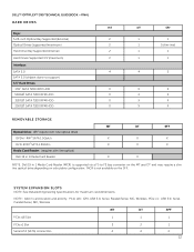
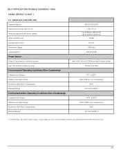
... MT and DT and may require a slim line optical drive depending on the SFF. DELL™ OPTIPLEX™ 390 TECHNICAL GUIDEBOOK -FINAL HARD DRIVES MT Bays: 5.25-inch Optical Bay Supported (External) 2 Optical Drives Supported (maximum) 2 Hard Drive Bay Supported (Internal) 2 Hard Drives Supported 3.5"(maximum) 2 Interface: SATA 2.0 4 SATA 3.0 (chipset does not support) 3.5" Hard Drives: 1TB1 SATA 7200 RPM HDD X 500GB1 SATA 7200 RPM...
... MT and DT and may require a slim line optical drive depending on the SFF. DELL™ OPTIPLEX™ 390 TECHNICAL GUIDEBOOK -FINAL HARD DRIVES MT Bays: 5.25-inch Optical Bay Supported (External) 2 Optical Drives Supported (maximum) 2 Hard Drive Bay Supported (Internal) 2 Hard Drives Supported 3.5"(maximum) 2 Interface: SATA 2.0 4 SATA 3.0 (chipset does not support) 3.5" Hard Drives: 1TB1 SATA 7200 RPM HDD X 500GB1 SATA 7200 RPM...
Technical Guide
Page 16
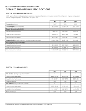
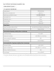
DELL™ OPTIPLEX™ 390 TECHNICAL GUIDEBOOK -FINAL DETAILED ENGINEERING SPECIFICATIONS SYSTEM DIMENSIONS (PHYSICAL) NOTE: System Weight and Shipping Weight is based on a typical configuration and may vary based on PC configuration. A typical configuration includes: integrated graphics, one hard drive, one optical drive. includes packaging materials) Packaging Parameters (HxWxD) Height (inches/centimeters) Width (inches/centimeters) Depth (inches...
DELL™ OPTIPLEX™ 390 TECHNICAL GUIDEBOOK -FINAL DETAILED ENGINEERING SPECIFICATIONS SYSTEM DIMENSIONS (PHYSICAL) NOTE: System Weight and Shipping Weight is based on a typical configuration and may vary based on PC configuration. A typical configuration includes: integrated graphics, one hard drive, one optical drive. includes packaging materials) Packaging Parameters (HxWxD) Height (inches/centimeters) Width (inches/centimeters) Depth (inches...
Technical Guide
Page 27
DELL™ OPTIPLEX™ 390 TECHNICAL GUIDEBOOK -FINAL HARD DRIVES1 3.5" 1TB SATA 7200 RPM HDD Capacity (bytes) Dimensions inches (W x D x H) Interface type and Maximum speed Internal buffer size Average Seek Time Rotational Speed Logical Blocks ...% to 80% non-condensing 290C -50 ft to 10000 ft -400C to 650C 10% to 90% non-condensing 380C -50 ft to 35000 ft 1 For hard drives, GB means 1 billion bytes ; actual capacity varies with preloaded material and operating environment and will be less. 27
DELL™ OPTIPLEX™ 390 TECHNICAL GUIDEBOOK -FINAL HARD DRIVES1 3.5" 1TB SATA 7200 RPM HDD Capacity (bytes) Dimensions inches (W x D x H) Interface type and Maximum speed Internal buffer size Average Seek Time Rotational Speed Logical Blocks ...% to 80% non-condensing 290C -50 ft to 10000 ft -400C to 650C 10% to 90% non-condensing 380C -50 ft to 35000 ft 1 For hard drives, GB means 1 billion bytes ; actual capacity varies with preloaded material and operating environment and will be less. 27

Technical Guide
Page 28
DELL™ OPTIPLEX™ 390 TECHNICAL GUIDEBOOK -FINAL HARD DRIVES1 (CONT.) 3.5" 500GB SATA 7200 RPM HDD Capacity (bytes) Dimensions inches (W x D x H) Interface type and Maximum speed Internal buffer size Average Seek Time Rotational Speed Logical ...% to 80% non-condensing 290C -50 ft to 10000 ft -400C to 650C 10% to 90% non-condensing 380C -50 ft to 35000 ft 1 For hard drives, GB means 1 billion bytes ; actual capacity varies with preloaded material and operating environment and will be less. 28
DELL™ OPTIPLEX™ 390 TECHNICAL GUIDEBOOK -FINAL HARD DRIVES1 (CONT.) 3.5" 500GB SATA 7200 RPM HDD Capacity (bytes) Dimensions inches (W x D x H) Interface type and Maximum speed Internal buffer size Average Seek Time Rotational Speed Logical ...% to 80% non-condensing 290C -50 ft to 10000 ft -400C to 650C 10% to 90% non-condensing 380C -50 ft to 35000 ft 1 For hard drives, GB means 1 billion bytes ; actual capacity varies with preloaded material and operating environment and will be less. 28
Technical Guide
Page 29
DELL™ OPTIPLEX™ 390 TECHNICAL GUIDEBOOK -FINAL HARD DRIVES1 (CONT.) 3.5" 320GB SATA 7200 RPM HDD Capacity (bytes) Dimensions inches (W x D x H) Interface type and Maximum speed Internal buffer size Average Seek Time Rotational Speed Logical ...% to 80% non-condensing 290C -50 ft to 10000 ft -400C to 650C 10% to 90% non-condensing 380C -50 ft to 35000 ft 1 For hard drives, GB means 1 billion bytes ; actual capacity varies with preloaded material and operating environment and will be less. 29
DELL™ OPTIPLEX™ 390 TECHNICAL GUIDEBOOK -FINAL HARD DRIVES1 (CONT.) 3.5" 320GB SATA 7200 RPM HDD Capacity (bytes) Dimensions inches (W x D x H) Interface type and Maximum speed Internal buffer size Average Seek Time Rotational Speed Logical ...% to 80% non-condensing 290C -50 ft to 10000 ft -400C to 650C 10% to 90% non-condensing 380C -50 ft to 35000 ft 1 For hard drives, GB means 1 billion bytes ; actual capacity varies with preloaded material and operating environment and will be less. 29
Technical Guide
Page 30
DELL™ OPTIPLEX™ 390 TECHNICAL GUIDEBOOK -FINAL HARD DRIVES1 (CONT.) 3.5" 250GB SATA 7200 RPM HDD Capacity (bytes) Dimensions inches (W x D x H) Interface type and Maximum speed Internal buffer size Average Seek Time Rotational Speed Logical ...% to 80% non-condensing 290C -50 ft to 10000 ft -400C to 650C 10% to 90% non-condensing 380C -50 ft to 35000 ft 1 For hard drives, GB means 1 billion bytes ; actual capacity varies with preloaded material and operating environment and will be less. 30
DELL™ OPTIPLEX™ 390 TECHNICAL GUIDEBOOK -FINAL HARD DRIVES1 (CONT.) 3.5" 250GB SATA 7200 RPM HDD Capacity (bytes) Dimensions inches (W x D x H) Interface type and Maximum speed Internal buffer size Average Seek Time Rotational Speed Logical ...% to 80% non-condensing 290C -50 ft to 10000 ft -400C to 650C 10% to 90% non-condensing 380C -50 ft to 35000 ft 1 For hard drives, GB means 1 billion bytes ; actual capacity varies with preloaded material and operating environment and will be less. 30

Owners Manual
Page 3
... Removing the Front Bezel 13 Installing The Front Bezel 14 4 Expansion Card Tab 15 Removing the Expansion Card 15 Installing The Expansion Card 16 5 Optical Drive 17 Removing the Optical Drive 17 Installing The Optical Drive 18 6 Hard Drive 19 Removing the Hard Drive 19 Installing The Hard Drive 20 7 Memory...21 Removing the Memory...21
... Removing the Front Bezel 13 Installing The Front Bezel 14 4 Expansion Card Tab 15 Removing the Expansion Card 15 Installing The Expansion Card 16 5 Optical Drive 17 Removing the Optical Drive 17 Installing The Optical Drive 18 6 Hard Drive 19 Removing the Hard Drive 19 Installing The Hard Drive 20 7 Memory...21 Removing the Memory...21

Owners Manual
Page 19
Flex the hard-drive bracket and then remove the single 3.5 inch hard drive or two 2.5 inch hard drives from the chassis. 4. Release the screws that secure the 2.5 inch hard drive to the top of the hard-drive bracket. 19 Remove the hard drive from the bracket. 6. Hard Drive 6 Removing the Hard Drive 1. Follow the procedures in Before Working Inside Your Computer. 2. Remove the cover. 3. Press the retention clips inwards and slide the hard-drive bracket from the drive cage. 5.
Flex the hard-drive bracket and then remove the single 3.5 inch hard drive or two 2.5 inch hard drives from the chassis. 4. Release the screws that secure the 2.5 inch hard drive to the top of the hard-drive bracket. 19 Remove the hard drive from the bracket. 6. Hard Drive 6 Removing the Hard Drive 1. Follow the procedures in Before Working Inside Your Computer. 2. Remove the cover. 3. Press the retention clips inwards and slide the hard-drive bracket from the drive cage. 5.

Owners Manual
Page 20
Press the retention clips inwards and slide the hard-drive bracket into the bracket. 3. Release the screws that secure the 2.5 inch hard drive to the hard drive bracket. 2. Tighten the screws to secures the two hard drives to the underside of the hard-drive bracket. Install the cover. 5. 7. Follow the procedures in After Working Inside Your Computer. 20 Installing The Hard Drive 1. Flex the hard-drive bracket and then insert the single hard drive or two hard drives into the drive cage. 4.
Press the retention clips inwards and slide the hard-drive bracket into the bracket. 3. Release the screws that secure the 2.5 inch hard drive to the hard drive bracket. 2. Tighten the screws to secures the two hard drives to the underside of the hard-drive bracket. Install the cover. 5. 7. Follow the procedures in After Working Inside Your Computer. 20 Installing The Hard Drive 1. Flex the hard-drive bracket and then insert the single hard drive or two hard drives into the drive cage. 4.

Owners Manual
Page 50
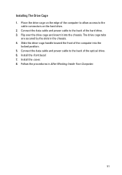
Remove the data cable and power cable from the computer. 50 Remove the drive cage from the back of the hard drive. 8. 7.
Remove the data cable and power cable from the computer. 50 Remove the drive cage from the back of the hard drive. 8. 7.
Owners Manual
Page 51
... the data cable and power cable to the back of the hard drive. 3. Flip over the drive cage and insert it into the locked position. 5. Connect the data cable and power cable to the back of the optical drive. 6. The drive cage tabs are secured by the slots in After Working Inside.... 51 Follow the procedures in the chassis. 4. Slide the drive-cage handle toward the front of the computer to allow access to the cable connectors on the hard drive. 2. Install the cover. 8. Install the front bezel. 7. Place the drive cage on the edge of the computer into the chassis. Installing...
... the data cable and power cable to the back of the hard drive. 3. Flip over the drive cage and insert it into the locked position. 5. Connect the data cable and power cable to the back of the optical drive. 6. The drive cage tabs are secured by the slots in After Working Inside.... 51 Follow the procedures in the chassis. 4. Slide the drive-cage handle toward the front of the computer to allow access to the cable connectors on the hard drive. 2. Install the cover. 8. Install the front bezel. 7. Place the drive cage on the edge of the computer into the chassis. Installing...
Owners Manual
Page 55
... prompting - If you are as follows: • Easier access - The boot menu includes two diagnostic options, IDE Drive Diagnostics (90/90 Hard Drive Diagnostics) and Boot to a specific device (for example: floppy, CD-ROM, or hard drive). Boot Menu This feature gives users a quick and convenient mechanism to bypass the System Setup-defined boot device...
... prompting - If you are as follows: • Easier access - The boot menu includes two diagnostic options, IDE Drive Diagnostics (90/90 Hard Drive Diagnostics) and Boot to a specific device (for example: floppy, CD-ROM, or hard drive). Boot Menu This feature gives users a quick and convenient mechanism to bypass the System Setup-defined boot device...

Owners Manual
Page 59
...-board: • SATA-0 • SATA-1 • SATA-2 • SATA-3 Smart Reporting USB Configuration This field controls whether hard drive errors for : • Boot Support • Rear Dual USB Ports • Front USB Ports • Rear Quad USB Ports Miscellaneous... Devices Allows you to set by default. 59 Displays the current status of the integrated hard drive controller. • Disabled = The SATA controllers are reported during system startup. SATA Operation Allows you to configure the operating mode of the ...
...-board: • SATA-0 • SATA-1 • SATA-2 • SATA-3 Smart Reporting USB Configuration This field controls whether hard drive errors for : • Boot Support • Rear Dual USB Ports • Front USB Ports • Rear Quad USB Ports Miscellaneous... Devices Allows you to set by default. 59 Displays the current status of the integrated hard drive controller. • Disabled = The SATA controllers are reported during system startup. SATA Operation Allows you to configure the operating mode of the ...
Owners Manual
Page 72
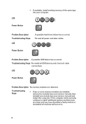
... the modules (see your computer. Troubleshooting Steps Re-install all USB devices and check all power and data cables. Problem Description Troubleshooting Steps LED A possible hard drive failure has occurred.
... the modules (see your computer. Troubleshooting Steps Re-install all USB devices and check all power and data cables. Problem Description Troubleshooting Steps LED A possible hard drive failure has occurred.
Owners Manual
Page 74
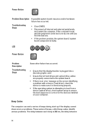
... codes, identify various problems. The delay between each beep is correct for the devices installed on the screen identifying a problem with a device ( hard drive), check the device to make sure it is functioning properly. • If the operating system is attempting to boot from a device (optical...one. • If the problem persists, the system board / system board component is faulty. Troubleshooting Steps • Clear CMOS. • Disconnect all hard drives and optical drive cables are properly connected to the system board. • If there is an error message on your computer.
... codes, identify various problems. The delay between each beep is correct for the devices installed on the screen identifying a problem with a device ( hard drive), check the device to make sure it is functioning properly. • If the operating system is attempting to boot from a device (optical...one. • If the problem persists, the system board / system board component is faulty. Troubleshooting Steps • Clear CMOS. • Disconnect all hard drives and optical drive cables are properly connected to the system board. • If there is an error message on your computer.


