User Manual
Page 4
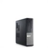
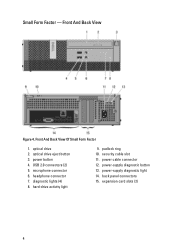
Front And Back View Of Small Form Factor 1. USB 2.0 connectors (2) 5. hard-drive activity light 9. power-supply diagnostic button 13. back panel connectors 15. optical drive 2. optical drive eject button 3. padlock ring 10. expansion card slots (2) 4 power-supply diagnostic light 14. security cable slot 11. headphone connector 7. power button 4. power cable connector 12. diagnostic lights (4) 8. microphone connector 6. Small Form Factor - Front And Back View Figure 4.
Front And Back View Of Small Form Factor 1. USB 2.0 connectors (2) 5. hard-drive activity light 9. power-supply diagnostic button 13. back panel connectors 15. optical drive 2. optical drive eject button 3. padlock ring 10. expansion card slots (2) 4 power-supply diagnostic light 14. security cable slot 11. headphone connector 7. power button 4. power cable connector 12. diagnostic lights (4) 8. microphone connector 6. Small Form Factor - Front And Back View Figure 4.
User Manual
Page 8
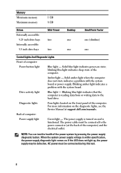
... start, indicates a problem with the system board. Back of computer: Power button light Blue light - When the system power supply voltage is turned on the front panel of the computer) and the electrical outlet. Memory Minimum memory Maximum memory 1 GB 8 GB Drives Externally accessible: 5.25 inch drive bays Internally accessible: 3.5 inch drive bays Mini-Tower two two Desktop one one Small Form Factor one (slimline) one Control Lights And Diagnostic Lights Front of computer: Power supply light Green light - The power supply...
... start, indicates a problem with the system board. Back of computer: Power button light Blue light - When the system power supply voltage is turned on the front panel of the computer) and the electrical outlet. Memory Minimum memory Maximum memory 1 GB 8 GB Drives Externally accessible: 5.25 inch drive bays Internally accessible: 3.5 inch drive bays Mini-Tower two two Desktop one one Small Form Factor one (slimline) one Control Lights And Diagnostic Lights Front of computer: Power supply light Green light - The power supply...
Technical Guide
Page 2
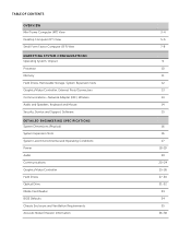
...) View MARKETING SYSTEM CONFIGURATIONS Operating System, Chipset Processor Memory Hard Drives, Removable Storage, System Expansion Slots Graphics/Video Controller, External Ports/Connectors Communications-Network Adapter (NIC), Wireless Audio and Speakers, Keyboard and Mouse Security, Service and Support, Software DETAILED ENGINEERING SPECIFICATIONS System Dimensions (Physical) System Expansion Slots System Level Environmental and Operating Conditions Power Audio Communications Graphics/Video Controller Hard Drives Optical Drive Media Card Reader BIOS Defaults Chassis Enclosure and Ventilation...
...) View MARKETING SYSTEM CONFIGURATIONS Operating System, Chipset Processor Memory Hard Drives, Removable Storage, System Expansion Slots Graphics/Video Controller, External Ports/Connectors Communications-Network Adapter (NIC), Wireless Audio and Speakers, Keyboard and Mouse Security, Service and Support, Software DETAILED ENGINEERING SPECIFICATIONS System Dimensions (Physical) System Expansion Slots System Level Environmental and Operating Conditions Power Audio Communications Graphics/Video Controller Hard Drives Optical Drive Media Card Reader BIOS Defaults Chassis Enclosure and Ventilation...
Technical Guide
Page 3
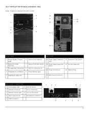
DELL™ OPTIPLEX™ 390 TECHNICAL GUIDEBOOK -FINAL MINI TOWER COMPUTER (MT) VIEW 1 6 10 7 11 15 2 12 16 8 3 4 9 5 13 14 FRONT VIEW BACK VIEW 1 Power Button, Power Light 6 Optical Drive (optional) 2 Optical Drive Bay (optional) 7 Optical Drive Eject Button 3 Microphone Connector 8 USB 2.0 Connectors (2) 4 Headphone Connector 9 Drive Activity Light 10 Power Supply Diagnostic 14 Expansion Card Slots(4) Light 11 Power Supply Diagnostic 15 Security Cable Slot Button 12 Power Connectors 16 Padlock Ring 5 Diagnostic Lights (4) 13 Back Panel Connectors BACK PANEL ...
DELL™ OPTIPLEX™ 390 TECHNICAL GUIDEBOOK -FINAL MINI TOWER COMPUTER (MT) VIEW 1 6 10 7 11 15 2 12 16 8 3 4 9 5 13 14 FRONT VIEW BACK VIEW 1 Power Button, Power Light 6 Optical Drive (optional) 2 Optical Drive Bay (optional) 7 Optical Drive Eject Button 3 Microphone Connector 8 USB 2.0 Connectors (2) 4 Headphone Connector 9 Drive Activity Light 10 Power Supply Diagnostic 14 Expansion Card Slots(4) Light 11 Power Supply Diagnostic 15 Security Cable Slot Button 12 Power Connectors 16 Padlock Ring 5 Diagnostic Lights (4) 13 Back Panel Connectors BACK PANEL ...
Technical Guide
Page 5
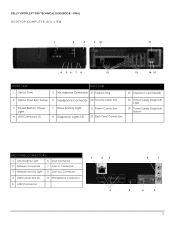
DELL™ OPTIPLEX™ 390 TECHNICAL GUIDEBOOK -FINAL DESKTOP COMPUTER (DT) VIEW 1 2 3 9 10 11 4 56 7 8 12 13 14 15 FRONT VIEW 1 Optical Drive BACK VIEW 5 Microphone Connector 9 Padlock Ring 13 Expansion Card Slots(4) 2 Optical Drive Eject Button 6 Headphone Connector 10 Security Cable Slot 3 Power Button, Power Light 4 USB Connectors (2) 7 Drive Activity Light 8 Diagnostic Lights (4) 11 Power Connectors 12 Back Panel Connectors 14 Power Supply Diagnostic Light 15 Power Supply Diagnostic Button BACK PANEL CONNECTORS 1 Link Integrity Light 6 VGA Connector 2 Network ...
DELL™ OPTIPLEX™ 390 TECHNICAL GUIDEBOOK -FINAL DESKTOP COMPUTER (DT) VIEW 1 2 3 9 10 11 4 56 7 8 12 13 14 15 FRONT VIEW 1 Optical Drive BACK VIEW 5 Microphone Connector 9 Padlock Ring 13 Expansion Card Slots(4) 2 Optical Drive Eject Button 6 Headphone Connector 10 Security Cable Slot 3 Power Button, Power Light 4 USB Connectors (2) 7 Drive Activity Light 8 Diagnostic Lights (4) 11 Power Connectors 12 Back Panel Connectors 14 Power Supply Diagnostic Light 15 Power Supply Diagnostic Button BACK PANEL CONNECTORS 1 Link Integrity Light 6 VGA Connector 2 Network ...
Technical Guide
Page 7
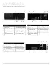
DELL™ OPTIPLEX™ 390 TECHNICAL GUIDEBOOK -FINAL SMALL FORM FACTOR COMPUTER (SFF) VIEW 1 2 3 9 10 11 12 13 4 56 7 8 14 15 FRONT VIEW 1 Optical Drive 5 Microphone Connector 2 Optical Drive Eject Button 6 Headphone Connector 3 Power Button, Power Light 4 USB 2.0 Connectors (2) 7 Diagnostic Lights (4) 8 Drive Activity Light BACK VIEW 9 Padlock Ring 10 Security Cable Slot 11 Power Connectors 13 Power Supply Diagnostic Light 14 Back Panel Connectors 15 Expansion Card Slots(2) 12 Power Supply Diagnostic Button BACK PANEL CONNECTORS 1 HDMI Connector 5 Link Integrity ...
DELL™ OPTIPLEX™ 390 TECHNICAL GUIDEBOOK -FINAL SMALL FORM FACTOR COMPUTER (SFF) VIEW 1 2 3 9 10 11 12 13 4 56 7 8 14 15 FRONT VIEW 1 Optical Drive 5 Microphone Connector 2 Optical Drive Eject Button 6 Headphone Connector 3 Power Button, Power Light 4 USB 2.0 Connectors (2) 7 Diagnostic Lights (4) 8 Drive Activity Light BACK VIEW 9 Padlock Ring 10 Security Cable Slot 11 Power Connectors 13 Power Supply Diagnostic Light 14 Back Panel Connectors 15 Expansion Card Slots(2) 12 Power Supply Diagnostic Button BACK PANEL CONNECTORS 1 HDMI Connector 5 Link Integrity ...
Technical Guide
Page 12
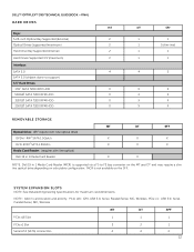
... support) 3.5" Hard Drives: 1TB1 SATA 7200 RPM HDD X 500GB1 SATA 7200 RPM HDD X 320GB1 SATA 7200 RPM HDD X 250GB1 SATA 7200 RPM HDD X DT SFF 1 1 1 1 (slim-line) 1 1 1 1 4 2 X X X X X X X X REMOVABLE STORAGE Optical Drive: (SFF require slim-line optical drive) DVD+/-RW2 SATA 1.5Gbit/s DVD-ROM3 SATA 1.5Gbit/s Media Card Reader: (requires slim line optical) Dell 19 in 1 Media Card Reader MT DT SFF X X X X X X X X NOTE: Dell 19 in card location and priority: PCIe x16: GFX, USB 3.0, Serial, Parallel/Serial, NIC, Wireless; PCIe x1: USB 3.0, Serial, Parallel...
... support) 3.5" Hard Drives: 1TB1 SATA 7200 RPM HDD X 500GB1 SATA 7200 RPM HDD X 320GB1 SATA 7200 RPM HDD X 250GB1 SATA 7200 RPM HDD X DT SFF 1 1 1 1 (slim-line) 1 1 1 1 4 2 X X X X X X X X REMOVABLE STORAGE Optical Drive: (SFF require slim-line optical drive) DVD+/-RW2 SATA 1.5Gbit/s DVD-ROM3 SATA 1.5Gbit/s Media Card Reader: (requires slim line optical) Dell 19 in 1 Media Card Reader MT DT SFF X X X X X X X X NOTE: Dell 19 in card location and priority: PCIe x16: GFX, USB 3.0, Serial, Parallel/Serial, NIC, Wireless; PCIe x1: USB 3.0, Serial, Parallel...
Technical Guide
Page 13
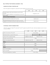
... combo] Intel HD Graphics 2000[with dual DVI or dual VGA (adapters convert DMS-59 connector to dual DVI or dual VGA) Optional card Optional card EXTERNAL PORTS/CONNECTORS NOTE: MT supports full height (FH) cards and DT and SFF supports low profile (LP) cards. DELL™ OPTIPLEX™ 390 TECHNICAL GUIDEBOOK -FINAL GRAPHICS/VIDEO CONTROLLER NOTE: MT supports full height (FH) cards and DT and SFF supports low profile (LP) cards. See chassis diagrams section for port/ connector locations USB 2.0 (1 internal on CPU 1GB AMD RADEON HD...
... combo] Intel HD Graphics 2000[with dual DVI or dual VGA (adapters convert DMS-59 connector to dual DVI or dual VGA) Optional card Optional card EXTERNAL PORTS/CONNECTORS NOTE: MT supports full height (FH) cards and DT and SFF supports low profile (LP) cards. DELL™ OPTIPLEX™ 390 TECHNICAL GUIDEBOOK -FINAL GRAPHICS/VIDEO CONTROLLER NOTE: MT supports full height (FH) cards and DT and SFF supports low profile (LP) cards. See chassis diagrams section for port/ connector locations USB 2.0 (1 internal on CPU 1GB AMD RADEON HD...
Technical Guide
Page 34
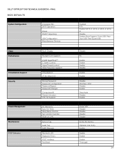
DELL™ OPTIPLEX™ 390 TECHNICAL GUIDEBOOK -FINAL BIOS DEFAULTS System Configuration Integrated NIC: SATA Operation: Drives: SMART Reporting: USB Configuration: Miscellaneous Devices: Video Performance Virtualization Support Security Power Management Maintenance POST Behavior Multi-Display: Multiple Core Support: Intel® SpeedStep™: C States Control: HyperThread control: HDD Protection Support Virtualization: VT for Direct I/O: Strong Password: Password Configuration: Password Bypass: Password Changes: Computrace®: Chassis Intrusion: CPU XD Support: AC Recovery: ...
DELL™ OPTIPLEX™ 390 TECHNICAL GUIDEBOOK -FINAL BIOS DEFAULTS System Configuration Integrated NIC: SATA Operation: Drives: SMART Reporting: USB Configuration: Miscellaneous Devices: Video Performance Virtualization Support Security Power Management Maintenance POST Behavior Multi-Display: Multiple Core Support: Intel® SpeedStep™: C States Control: HyperThread control: HDD Protection Support Virtualization: VT for Direct I/O: Strong Password: Password Configuration: Password Bypass: Password Changes: Computrace®: Chassis Intrusion: CPU XD Support: AC Recovery: ...
Owners Manual
Page 5
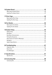
16 System Board 45 Removing the System Board 45 Installing The System Board 47 17 Drive Cage 49 Removing the Drive Cage 49 Installing The Drive Cage 51 18 Fan Shelter 53 Removing the Fan Shelter 53 Installing The Fan Shelter 53 19 System Setup 55 System Setup...55 Boot Menu...55 Boot Menu Enhancements 55 Timing Key Sequences...56 Beep Codes and Text Error Messages 57 Navigation...57 System Setup Options...57 20 Troubleshooting 67 Diagnostic LEDs...67 Beep Codes...74 Error Messages...77 21 Specifications 81 Specification...81 22 Contacting Dell 89 Contacting Dell...89
16 System Board 45 Removing the System Board 45 Installing The System Board 47 17 Drive Cage 49 Removing the Drive Cage 49 Installing The Drive Cage 51 18 Fan Shelter 53 Removing the Fan Shelter 53 Installing The Fan Shelter 53 19 System Setup 55 System Setup...55 Boot Menu...55 Boot Menu Enhancements 55 Timing Key Sequences...56 Beep Codes and Text Error Messages 57 Navigation...57 System Setup Options...57 20 Troubleshooting 67 Diagnostic LEDs...67 Beep Codes...74 Error Messages...77 21 Specifications 81 Specification...81 22 Contacting Dell 89 Contacting Dell...89
Owners Manual
Page 55
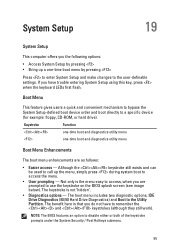
... trouble entering System Setup using this key, press when the keyboard LEDs first flash. Although the keystroke still exists and can be used to call up a one -time boot and diagnostics utility menu Boot Menu Enhancements The boot menu enhancements are prompted to remember the and keystrokes (although they still work). The keystroke is that you have to use the keystroke on the BIOS splash screen (see image below). The boot menu includes two diagnostic options...
... trouble entering System Setup using this key, press when the keyboard LEDs first flash. Although the keystroke still exists and can be used to call up a one -time boot and diagnostics utility menu Boot Menu Enhancements The boot menu enhancements are prompted to remember the and keystrokes (although they still work). The keystroke is that you have to use the keystroke on the BIOS splash screen (see image below). The boot menu includes two diagnostic options...
Owners Manual
Page 57
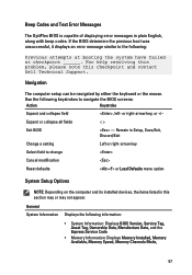
... the BIOS screens: Action Keystroke Expand and collapse field , left- General System Information Displays the following : Previous attempts at booting the system have failed at checkpoint ______. Use the following keystrokes to change Cancel modification Reset defaults or Load Defaults menu option System Setup Options NOTE: Depending on the computer and its installed devices, the items listed in plain English, along with beep codes. or right-arrow key, or...
... the BIOS screens: Action Keystroke Expand and collapse field , left- General System Information Displays the following : Previous attempts at booting the system have failed at checkpoint ______. Use the following keystrokes to change Cancel modification Reset defaults or Load Defaults menu option System Setup Options NOTE: Depending on the computer and its installed devices, the items listed in plain English, along with beep codes. or right-arrow key, or...
Owners Manual
Page 58
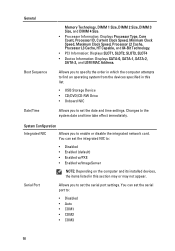
... Configuration Integrated NIC Allows you to set the serial port to enable or disable the integrated network card. Allows you to specify the order in which the computer attempts to find an operating system from the devices specified in this list. • USB Storage Device • CD/DVD/CD-RW Drive • Onboard NIC Allows you to the system date and time take effect immediately. Changes...
... Configuration Integrated NIC Allows you to set the serial port to enable or disable the integrated network card. Allows you to specify the order in which the computer attempts to find an operating system from the devices specified in this list. • USB Storage Device • CD/DVD/CD-RW Drive • Onboard NIC Allows you to the system date and time take effect immediately. Changes...
Owners Manual
Page 63
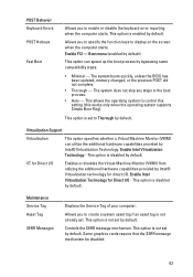
... for Direct I/O Enables or disables the Virtual Machine Monitor (VMM) from utilizing the additional hardware capabilities provided by default. Virtualization Support Virtualization This option specifies whether a Virtual Machine Monitor (VMM) can speed up the boot process by Intel® Virtualization Technology. Some graphics cards require that the SERR message mechanism be disabled. 63 Controls the SERR message mechanism. The system boots quickly, unless the BIOS has been updated, memory changed, or the...
... for Direct I/O Enables or disables the Virtual Machine Monitor (VMM) from utilizing the additional hardware capabilities provided by default. Virtualization Support Virtualization This option specifies whether a Virtual Machine Monitor (VMM) can speed up the boot process by Intel® Virtualization Technology. Some graphics cards require that the SERR message mechanism be disabled. 63 Controls the SERR message mechanism. The system boots quickly, unless the BIOS has been updated, memory changed, or the...
Owners Manual
Page 69
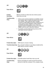
... a different DIMM connector and re-start the computer. Troubleshooting Steps The computer hardware is installed, try moving it to install additional memory modules (one module and re-start the computer. LED Power Button Problem Description BIOS may be corrupt or missing. Remove all modules without error. LED Power Button Problem Description Troubleshooting Steps A possible system board failure has occurred. If the computer boots, 69 If only one memory module is operating normally but a memory power failure has occurred...
... a different DIMM connector and re-start the computer. Troubleshooting Steps The computer hardware is installed, try moving it to install additional memory modules (one module and re-start the computer. LED Power Button Problem Description BIOS may be corrupt or missing. Remove all modules without error. LED Power Button Problem Description Troubleshooting Steps A possible system board failure has occurred. If the computer boots, 69 If only one memory module is operating normally but a memory power failure has occurred...
Owners Manual
Page 71
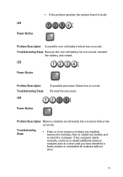
... battery, and restart. Problem Description A possible coin cell battery failure has occurred. Power Button Problem Description Memory modules are installed, remove the modules, then re-install one module and re-start the computer. Troubleshooting Steps • If two or more memory modules are detected, but a memory failure has occurred. LED Power Button • If the problem persists, the system board is faulty. LED Power Button Problem Description Troubleshooting Steps LED A possible processor failure has occurred. Troubleshooting Steps Remove the coin cell battery...
... battery, and restart. Problem Description A possible coin cell battery failure has occurred. Power Button Problem Description Memory modules are installed, remove the modules, then re-install one module and re-start the computer. Troubleshooting Steps • If two or more memory modules are detected, but a memory failure has occurred. LED Power Button • If the problem persists, the system board is faulty. LED Power Button Problem Description Troubleshooting Steps LED A possible processor failure has occurred. Troubleshooting Steps Remove the coin cell battery...
Owners Manual
Page 72
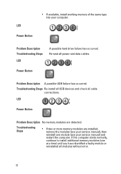
... hard drive failure has occurred. Re-seat all cable connections. Troubleshooting Steps Re-install all USB devices and check all power and data cables. LED Power Button • If available, install working memory of the same type into your service manual) and restart the computer. LED Power Button Problem Description No memory modules are installed, remove the modules (see your computer. Troubleshooting Steps • If two or more memory modules are detected. Power Button Problem Description A possible USB failure has occurred. If the computer starts...
... hard drive failure has occurred. Re-seat all cable connections. Troubleshooting Steps Re-install all USB devices and check all power and data cables. LED Power Button • If available, install working memory of the same type into your service manual) and restart the computer. LED Power Button Problem Description No memory modules are installed, remove the modules (see your computer. Troubleshooting Steps • If two or more memory modules are detected. Power Button Problem Description A possible USB failure has occurred. If the computer starts...
Owners Manual
Page 73
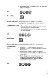
... memory module/connector placement exist. LED Power Button Problem Description A possible expansion card failure has occurred. Troubleshooting Steps • Determine if a conflict exists by your computer. LED 73 Problem Description Memory modules are using is supported by removing an expansion card (not a graphics card) and restarting the computer. • If the problem persists, reinstall the card you are detected, but a memory configuration or compatibility error has occurred. If the computer starts normally, troubleshoot the last card removed...
... memory module/connector placement exist. LED Power Button Problem Description A possible expansion card failure has occurred. Troubleshooting Steps • Determine if a conflict exists by your computer. LED 73 Problem Description Memory modules are using is supported by removing an expansion card (not a graphics card) and restarting the computer. • If the problem persists, reinstall the card you are detected, but a memory configuration or compatibility error has occurred. If the computer starts normally, troubleshoot the last card removed...
Owners Manual
Page 74
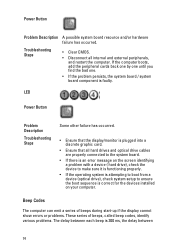
.../or hardware failure has occurred. Troubleshooting Steps • Clear CMOS. • Disconnect all hard drives and optical drive cables are properly connected to the system board. • If there is an error message on your computer. Beep Codes The computer can emit a series of beeps during start-up if the display cannot show errors or problems. These series of beeps, called beep codes, identify various problems. The delay between 74 If the computer boots, add the peripheral cards back...
.../or hardware failure has occurred. Troubleshooting Steps • Clear CMOS. • Disconnect all hard drives and optical drive cables are properly connected to the system board. • If there is an error message on your computer. Beep Codes The computer can emit a series of beeps during start-up if the display cannot show errors or problems. These series of beeps, called beep codes, identify various problems. The delay between 74 If the computer boots, add the peripheral cards back...
Owners Manual
Page 79
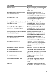
... boot sector on the system board might be malfunctioning. Reinstall the memory modules and, if necessary, replace them . No timer tick interrupt A chip on hard-disk drive The computer configuration information in the computer. Plug and play configuration error The computer encountered a problem while trying to run is conflicting with the operating system, another program, or a utility. Memory double word logic failure at address, read from the hard drive...
... boot sector on the system board might be malfunctioning. Reinstall the memory modules and, if necessary, replace them . No timer tick interrupt A chip on hard-disk drive The computer configuration information in the computer. Plug and play configuration error The computer encountered a problem while trying to run is conflicting with the operating system, another program, or a utility. Memory double word logic failure at address, read from the hard drive...


