User Manual
Page 1
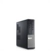
... - 05 optical drive 7. USB 2.0 connectors (2) 9. hard-drive activity light 10. Front And Back View Figure 1. diagnostic lights (4) 6. power-supply diagnostic button 12. Front And Back View Of Mini-Tower 1. Mini-Tower - optical drive eject button 8. Dell Optiplex 390 Setup And Features Information About Warnings WARNING: A WARNING indicates a potential for property damage, personal injury, or death...
... - 05 optical drive 7. USB 2.0 connectors (2) 9. hard-drive activity light 10. Front And Back View Figure 1. diagnostic lights (4) 6. power-supply diagnostic button 12. Front And Back View Of Mini-Tower 1. Mini-Tower - optical drive eject button 8. Dell Optiplex 390 Setup And Features Information About Warnings WARNING: A WARNING indicates a potential for property damage, personal injury, or death...
User Manual
Page 2
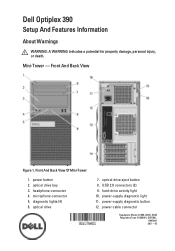
security cable slot 16. Front And Back View Of Desktop 1. USB 2.0 connectors (2) 5. hard-drive activity light 8. power cable connector 12. back panel connectors 14. optical drive eject button 3. microphone connector 6. Front And Back View 15. optical drive 2. back panel connectors 13. expansion card slots (4) 14. power-supply diagnostic light 15. expansion card slots (4) Desktop - diagnostic lights (4) 9. 13. headphone connector 7. power button 4. security cable slot 11. padlock ring Figure 2. padlock ring 10. power-supply diagnostic button 2
security cable slot 16. Front And Back View Of Desktop 1. USB 2.0 connectors (2) 5. hard-drive activity light 8. power cable connector 12. back panel connectors 14. optical drive eject button 3. microphone connector 6. Front And Back View 15. optical drive 2. back panel connectors 13. expansion card slots (4) 14. power-supply diagnostic light 15. expansion card slots (4) Desktop - diagnostic lights (4) 9. 13. headphone connector 7. power button 4. security cable slot 11. padlock ring Figure 2. padlock ring 10. power-supply diagnostic button 2
User Manual
Page 4
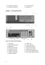
Front And Back View Of Small Form Factor 1. optical drive 2. optical drive eject button 3. diagnostic lights (4) 8. back panel connectors 15. hard-drive activity light 9. USB 2.0 connectors (2) 5. power cable connector 12. microphone connector 6. power-supply diagnostic button 13. Front And Back View Figure 4. power-supply diagnostic light 14. security cable slot 11. expansion card slots (2) 4 power button 4. headphone connector 7. padlock ring 10. Small Form Factor -
Front And Back View Of Small Form Factor 1. optical drive 2. optical drive eject button 3. diagnostic lights (4) 8. back panel connectors 15. hard-drive activity light 9. USB 2.0 connectors (2) 5. power cable connector 12. microphone connector 6. power-supply diagnostic button 13. Front And Back View Figure 4. power-supply diagnostic light 14. security cable slot 11. expansion card slots (2) 4 power button 4. headphone connector 7. padlock ring 10. Small Form Factor -
User Manual
Page 8
... connected during this test. 8 Solid blue light indicates power-on . When the system power supply voltage is reading data from or writing data to the power connector (at support.dell.com/manuals. blinking blue light indicates sleep state of the power system by pressing the power-supply diagnostic button. The power cable must be defective. For more information on...
... connected during this test. 8 Solid blue light indicates power-on . When the system power supply voltage is reading data from or writing data to the power connector (at support.dell.com/manuals. blinking blue light indicates sleep state of the power system by pressing the power-supply diagnostic button. The power cable must be defective. For more information on...
User Manual
Page 9
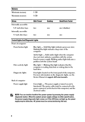
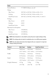
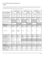
...: See the safety information that shipped with your computer for important voltage-setting information. NOTE: The voltage selector switch is calculated by using the power supply wattage rating. Power Coin-cell battery 3 V CR2032 lithium coin cell Voltage Mini-Tower 100 VAC to 240 VAC, 50 Hz to 60 Hz, 5.0 A Desktop 100 VAC to... dissipation Mini-Tower 1390 BTU/hr Desktop 1312 BTU/hr Small Form Factor 1259 BTU/hr NOTE: Heat dissipation is available only on non-EPA power supplies.
...: See the safety information that shipped with your computer for important voltage-setting information. NOTE: The voltage selector switch is calculated by using the power supply wattage rating. Power Coin-cell battery 3 V CR2032 lithium coin cell Voltage Mini-Tower 100 VAC to 240 VAC, 50 Hz to 60 Hz, 5.0 A Desktop 100 VAC to... dissipation Mini-Tower 1390 BTU/hr Desktop 1312 BTU/hr Small Form Factor 1259 BTU/hr NOTE: Heat dissipation is available only on non-EPA power supplies.
Technical Guide
Page 3
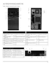
DELL™ OPTIPLEX™ 390 TECHNICAL GUIDEBOOK -FINAL MINI TOWER COMPUTER (MT) VIEW 1 6 10 7 11 15 2 12 16 8 3 4 9 5 13 14 FRONT VIEW BACK VIEW 1 Power Button, Power Light 6 Optical Drive (optional) 2 Optical Drive Bay (optional) 7 Optical Drive Eject Button 3 Microphone Connector 8 USB 2.0 Connectors (2) 4 Headphone Connector 9 Drive Activity Light 10 Power Supply Diagnostic 14 Expansion Card Slots(4) Light 11...
DELL™ OPTIPLEX™ 390 TECHNICAL GUIDEBOOK -FINAL MINI TOWER COMPUTER (MT) VIEW 1 6 10 7 11 15 2 12 16 8 3 4 9 5 13 14 FRONT VIEW BACK VIEW 1 Power Button, Power Light 6 Optical Drive (optional) 2 Optical Drive Bay (optional) 7 Optical Drive Eject Button 3 Microphone Connector 8 USB 2.0 Connectors (2) 4 Headphone Connector 9 Drive Activity Light 10 Power Supply Diagnostic 14 Expansion Card Slots(4) Light 11...
Technical Guide
Page 5
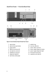
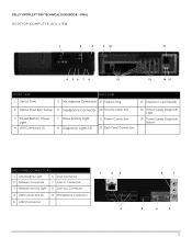
DELL™ OPTIPLEX™ 390 TECHNICAL GUIDEBOOK -FINAL DESKTOP COMPUTER (DT) VIEW 1 2 3 9 10 11 4 56 7 8 12 13 14 15 FRONT VIEW 1 Optical Drive BACK VIEW 5 Microphone Connector 9 Padlock Ring 13 Expansion Card Slots(4) 2 Optical Drive Eject Button 6 Headphone Connector 10 Security Cable Slot 3 Power Button, Power Light 4 USB Connectors (2) 7 Drive Activity Light 8 Diagnostic Lights (4) 11 Power Connectors...
DELL™ OPTIPLEX™ 390 TECHNICAL GUIDEBOOK -FINAL DESKTOP COMPUTER (DT) VIEW 1 2 3 9 10 11 4 56 7 8 12 13 14 15 FRONT VIEW 1 Optical Drive BACK VIEW 5 Microphone Connector 9 Padlock Ring 13 Expansion Card Slots(4) 2 Optical Drive Eject Button 6 Headphone Connector 10 Security Cable Slot 3 Power Button, Power Light 4 USB Connectors (2) 7 Drive Activity Light 8 Diagnostic Lights (4) 11 Power Connectors...
Technical Guide
Page 7
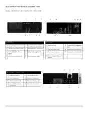
DELL™ OPTIPLEX™ 390 TECHNICAL GUIDEBOOK -FINAL SMALL FORM FACTOR COMPUTER (SFF) VIEW 1 2 3 9 10 11 12 13 4 56 7 8 14 15 FRONT VIEW 1 Optical Drive 5 Microphone Connector 2 Optical Drive Eject Button 6 Headphone Connector 3 Power Button, Power Light 4 USB 2.0 Connectors (2) 7 Diagnostic Lights (4) 8 Drive Activity Light BACK VIEW 9 Padlock Ring 10 Security Cable Slot 11 Power Connectors 13 Power Supply... Diagnostic Light 14 Back Panel Connectors 15 Expansion Card Slots(2) 12 Power Supply Diagnostic Button BACK ...
DELL™ OPTIPLEX™ 390 TECHNICAL GUIDEBOOK -FINAL SMALL FORM FACTOR COMPUTER (SFF) VIEW 1 2 3 9 10 11 12 13 4 56 7 8 14 15 FRONT VIEW 1 Optical Drive 5 Microphone Connector 2 Optical Drive Eject Button 6 Headphone Connector 3 Power Button, Power Light 4 USB 2.0 Connectors (2) 7 Diagnostic Lights (4) 8 Drive Activity Light BACK VIEW 9 Padlock Ring 10 Security Cable Slot 11 Power Connectors 13 Power Supply... Diagnostic Light 14 Back Panel Connectors 15 Expansion Card Slots(2) 12 Power Supply Diagnostic Button BACK ...
Technical Guide
Page 18
... output -12.0v output Max total power Max combined +3.3v / +5.0v power Max combined 12.0v power (note: only if more efficient Active Power Factor Correction (APFC) power supply. Dell recommends only Universal Power Supplies (UPS) based on PSU max wattage) Power Supply Fan Compliance: 1watt requirement Blue Angel Compliant... Yes Yes Yes Yes 18 If you have questions, please contact the manufacture to confirm the output type. DELL™ OPTIPLEX™ 390 TECHNICAL GUIDEBOOK -FINAL POWER NOTE: These form factors utilize a more than one 12v rail) BTUs/h (based on Sine Wave output ...
... output -12.0v output Max total power Max combined +3.3v / +5.0v power Max combined 12.0v power (note: only if more efficient Active Power Factor Correction (APFC) power supply. Dell recommends only Universal Power Supplies (UPS) based on PSU max wattage) Power Supply Fan Compliance: 1watt requirement Blue Angel Compliant... Yes Yes Yes Yes 18 If you have questions, please contact the manufacture to confirm the output type. DELL™ OPTIPLEX™ 390 TECHNICAL GUIDEBOOK -FINAL POWER NOTE: These form factors utilize a more than one 12v rail) BTUs/h (based on Sine Wave output ...
Technical Guide
Page 19
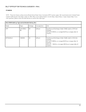
DELL™ OPTIPLEX™ 390 TECHNICAL GUIDEBOOK -FINAL POWER NOTE: These form factors utilize a more efficient Active Power Factor Correction (APFC) power supply. or Longer.820Hrs.or Longer after 12 months. Dell recommends only Universal Power Supplies (UPS) based on Sine Wave output for APFC PSUs, not an approximation of a Sine Wave, Square Wave, or quasi-Square Wave. or Longer.910Hrs...
DELL™ OPTIPLEX™ 390 TECHNICAL GUIDEBOOK -FINAL POWER NOTE: These form factors utilize a more efficient Active Power Factor Correction (APFC) power supply. or Longer.820Hrs.or Longer after 12 months. Dell recommends only Universal Power Supplies (UPS) based on Sine Wave output for APFC PSUs, not an approximation of a Sine Wave, Square Wave, or quasi-Square Wave. or Longer.910Hrs...
Owners Manual
Page 4
... 33 Removing the Power-Switch Cable 33 Installing The Power Switch Cable 34 13 System Fan 35 Removing the System Fan 35 Installing The System Fan 36 14 Input/Output Panel 37 Removing The Input/Output (I/O) Panel 37 Installing The Input/Output (I/O) Panel 39 15 Power Supply 41 Removing the Power Supply 41 Installing The Power Supply 43
... 33 Removing the Power-Switch Cable 33 Installing The Power Switch Cable 34 13 System Fan 35 Removing the System Fan 35 Installing The System Fan 36 14 Input/Output Panel 37 Removing The Input/Output (I/O) Panel 37 Installing The Input/Output (I/O) Panel 39 15 Power Supply 41 Removing the Power Supply 41 Installing The Power Supply 43

Owners Manual
Page 41
Remove the fan shelter. 6. Remove the drive cage. 5. Unthread the 4-pin power cable from the system board. 41 Disconnect the 24-pin power cable from the chassis clips. 8. Disconnect the 4-pin power cable from the system board. 7. Follow the procedures in Before Working Inside Your Computer. 2. Remove the front bezel. 4. Remove the cover. 3. Power Supply 15 Removing the Power Supply 1.
Remove the fan shelter. 6. Remove the drive cage. 5. Unthread the 4-pin power cable from the system board. 41 Disconnect the 24-pin power cable from the chassis clips. 8. Disconnect the 4-pin power cable from the system board. 7. Follow the procedures in Before Working Inside Your Computer. 2. Remove the front bezel. 4. Remove the cover. 3. Power Supply 15 Removing the Power Supply 1.

Owners Manual
Page 42
9. Push in on the blue release tab beside the power supply, and slide the power supply towards the front of the computer. 10. Remove the screws that secure the power supply, from the back of the computer. 11. Lift the power supply out of the computer. 42
9. Push in on the blue release tab beside the power supply, and slide the power supply towards the front of the computer. 10. Remove the screws that secure the power supply, from the back of the computer. 11. Lift the power supply out of the computer. 42

Owners Manual
Page 43
Connect the power cable to the back of the computer. 3. Install the drive cage. 8. Installing The Power Supply 1. Use a Phillips screwdriver to tighten the three screws securing the power supply to the system board. 4. Follow the procedures in the chassis and slide outward to the system board. 6. Thread the power cable into the chassis clips. 5. Install the fan shelter. 7. Install the front bezel. 9. Place the power supply in After Working Inside Your Computer. 43 Connect the power cable to secure it. 2. Install the cover. 10.
Connect the power cable to the back of the computer. 3. Install the drive cage. 8. Installing The Power Supply 1. Use a Phillips screwdriver to tighten the three screws securing the power supply to the system board. 4. Follow the procedures in the chassis and slide outward to the system board. 6. Thread the power cable into the chassis clips. 5. Install the fan shelter. 7. Install the front bezel. 9. Place the power supply in After Working Inside Your Computer. 43 Connect the power cable to secure it. 2. Install the cover. 10.
Owners Manual
Page 47
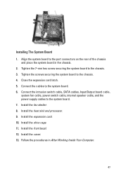
... expansion card. 10. Install the cover. 13. Connect the intrusion switch cable, SATA cables, Input/Output board cable, system fan cable, power switch cable, internal speaker cable, and the power supply cables to the port connectors on the rear of the chassis and place the system board in After Working Inside Your Computer...
... expansion card. 10. Install the cover. 13. Connect the intrusion switch cable, SATA cables, Input/Output board cable, system fan cable, power switch cable, internal speaker cable, and the power supply cables to the port connectors on the rear of the chassis and place the system board in After Working Inside Your Computer...
Owners Manual
Page 62
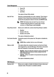
... Override Controls the speed of the system fan. This feature only works when the computer is connected to be powered on LAN This option allows the computer to power up signal from the off your computer starts. This option is Disabled by default. Time is kept in the...typing the values in standard 12-hour format (hour:minutes:seconds). Change the startup time by a special LAN signal. Allows the system to AC power supply. • Disabled - Sets time to disabled. This option is enabled by default. POST Behavior Numlock LED Allows you to enable or disable ...
... Override Controls the speed of the system fan. This feature only works when the computer is connected to be powered on LAN This option allows the computer to power up signal from the off your computer starts. This option is Disabled by default. Time is kept in the...typing the values in standard 12-hour format (hour:minutes:seconds). Change the startup time by a special LAN signal. Allows the system to AC power supply. • Disabled - Sets time to disabled. This option is enabled by default. POST Behavior Numlock LED Allows you to enable or disable ...

Owners Manual
Page 68
... from the system board, then press and hold the power supply test button at the rear of the power supply unit. Plug the computer into a working electrical outlet and press the power button. Press and hold the power supply button. If the LED next to the switch illuminates,...• If the LED next to the switch does not illuminate, disconnect all internal and external peripherals, and press and hold the power supply test button. Troubleshooting Steps Unplug the computer. Problem Description A possible system board failure has occurred. If it illuminates, there could be...
... from the system board, then press and hold the power supply test button at the rear of the power supply unit. Plug the computer into a working electrical outlet and press the power button. Press and hold the power supply button. If the LED next to the switch illuminates,...• If the LED next to the switch does not illuminate, disconnect all internal and external peripherals, and press and hold the power supply test button. Troubleshooting Steps Unplug the computer. Problem Description A possible system board failure has occurred. If it illuminates, there could be...

Owners Manual
Page 70
... failure has occurred. • Disconnect all peripheral cards from the power supply unit. Remove all internal and external peripherals, and re-start the computer. LED Power Button Problem Description Troubleshooting Steps Possible peripheral card or system board failure has occurred. Problem Description Power connector not installed properly. If the computer boots, add the peripheral...
... failure has occurred. • Disconnect all peripheral cards from the power supply unit. Remove all internal and external peripherals, and re-start the computer. LED Power Button Problem Description Troubleshooting Steps Possible peripheral card or system board failure has occurred. Problem Description Power connector not installed properly. If the computer boots, add the peripheral...
Owners Manual
Page 85
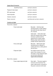
...not start indicates a problem with the system board. Four lights located on state; The power supply is turned on the diagnostic lights, see the Service Manual at the back 85 The power cable must be connected to the hard drive. blinking blue light indicates sleep state of ...light - Blinking amber light indicates a problem with the system board or power supply. Amber light - Blue light - For more information on and is reading data from or writing data to the power connector (at support.dell.com/manuals. System Board Connectors Small Form Factor Password clear jumper RTC ...
...not start indicates a problem with the system board. Four lights located on state; The power supply is turned on the diagnostic lights, see the Service Manual at the back 85 The power cable must be connected to the hard drive. blinking blue light indicates sleep state of ...light - Blinking amber light indicates a problem with the system board or power supply. Amber light - Blue light - For more information on and is reading data from or writing data to the power connector (at support.dell.com/manuals. System Board Connectors Small Form Factor Password clear jumper RTC ...
Owners Manual
Page 86
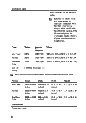
...to 240 VAC, 50 Hz to 60 Hz, 3.6 A; 3 V CR2032 lithium coin cell NOTE: Heat dissipation is within specification, the self-test LED lights up , the power supply may be connected during this test. NOTE: You can test the health of the computer) and the electrical outlet. If the LED does not light... up . Controls and Lights of the power system by using the power supply wattage rating. Physical Mini-Tower Desktop Small Form Factor Height Width 36.00 cm (14.17 17.50 cm (6.89 inches) inches) ...
...to 240 VAC, 50 Hz to 60 Hz, 3.6 A; 3 V CR2032 lithium coin cell NOTE: Heat dissipation is within specification, the self-test LED lights up , the power supply may be connected during this test. NOTE: You can test the health of the computer) and the electrical outlet. If the LED does not light... up . Controls and Lights of the power system by using the power supply wattage rating. Physical Mini-Tower Desktop Small Form Factor Height Width 36.00 cm (14.17 17.50 cm (6.89 inches) inches) ...


