Statement of Volatility
Page 1
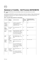
...) Embedded U54 Flash in text. The Dell Precision M4700/M6700 contains both volatile and non-volatile (NV) components. Non-volatile (NV) components continue to four modules must be populated. Table 1. DDR3 memory Four SODIMM connectors: Volatile memory in OFF state Yes NOTE: See state...(nVidia BIOS. Statement of panel assembly N/A N/A Power off system N/A Month yyyy List of embedded Flash No memory for basic boot operation, PSA (on the Dell Precision M4700/M6700 system board. Volatile components lose their data even after power is removed from the component. U52 (8M) U53...
...) Embedded U54 Flash in text. The Dell Precision M4700/M6700 contains both volatile and non-volatile (NV) components. Non-volatile (NV) components continue to four modules must be populated. Table 1. DDR3 memory Four SODIMM connectors: Volatile memory in OFF state Yes NOTE: See state...(nVidia BIOS. Statement of panel assembly N/A N/A Power off system N/A Month yyyy List of embedded Flash No memory for basic boot operation, PSA (on the Dell Precision M4700/M6700 system board. Volatile components lose their data even after power is removed from the component. U52 (8M) U53...
Statement of Volatility
Page 2
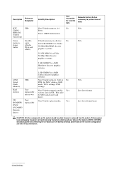
... Heathrow discrete graphics systems. 1 GB GDDR5 for AMD Chelsea discrete graphics systems. LOM Serial Flash Memory UH4 Non Volatile memory, built in No PCH, for external data Remedial Action (Action necessary to prevent loss of -day information. 2012 Dell Inc. User Non Volatile optical media. Yes ROM/RW/ replaceable DVD/ DVD+RW/ Diskette...
... Heathrow discrete graphics systems. 1 GB GDDR5 for AMD Chelsea discrete graphics systems. LOM Serial Flash Memory UH4 Non Volatile memory, built in No PCH, for external data Remedial Action (Action necessary to prevent loss of -day information. 2012 Dell Inc. User Non Volatile optical media. Yes ROM/RW/ replaceable DVD/ DVD+RW/ Diskette...

Owner's Manual
Page 4
Removing the Keyboard...24 Installing the Keyboard...26 Removing the Primary Memory...26 Installing the Primary Memory...27 Removing the Secondary Memory...27 Installing the Secondary Memory...28 Removing the Bluetooth Module...28 Installing the Bluetooth Module...29 Removing the Display Bezel...29 Installing the Display Bezel...31 Removing the Camera...31 ...
Removing the Keyboard...24 Installing the Keyboard...26 Removing the Primary Memory...26 Installing the Primary Memory...27 Removing the Secondary Memory...27 Installing the Secondary Memory...28 Removing the Bluetooth Module...28 Installing the Bluetooth Module...29 Removing the Display Bezel...29 Installing the Display Bezel...31 Removing the Camera...31 ...
Owner's Manual
Page 26
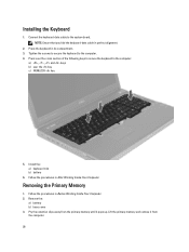
... from the computer. 26 NOTE: Ensure that you fold the keyboard-data cable in After Working Inside Your Computer. Lift the primary memory and remove it from the primary memory until it pops up. Press over the cross section of the following keys to secure the keyboard to the computer. 4. Install the...
... from the computer. 26 NOTE: Ensure that you fold the keyboard-data cable in After Working Inside Your Computer. Lift the primary memory and remove it from the primary memory until it pops up. Press over the cross section of the following keys to secure the keyboard to the computer. 4. Install the...

Owner's Manual
Page 27
... Working Inside Your Computer. Pry the retention clips away from the memory module until it pops up the memory module and remove it from the computer. 27 Installing the Primary Memory 1. Press the clips to secure the primary memory to the computer and remove the memory shield. 4. Install the: a) base cover b) battery 4. Removing the Secondary...
... Working Inside Your Computer. Pry the retention clips away from the memory module until it pops up the memory module and remove it from the computer. 27 Installing the Primary Memory 1. Press the clips to secure the primary memory to the computer and remove the memory shield. 4. Install the: a) base cover b) battery 4. Removing the Secondary...
Owner's Manual
Page 28
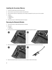
... 1. Disconnect and un-route the bluetooth cable. Disconnect and remove the bluetooth cable from the computer. Press the clips to secure the memory module to release it to the computer. 4. Follow the procedures in Before Working Inside Your Computer. 2. Remove the: a) battery b) base...in its original position on the computer and tighten the screw to secure it . 4. Installing the Secondary Memory 1. Insert the secondary memory into the memory socket. 2. Remove the bluetooth module. Place the memory shield in place. 5. Remove the bluetooth module from the module. 28
... 1. Disconnect and un-route the bluetooth cable. Disconnect and remove the bluetooth cable from the computer. Press the clips to secure the memory module to release it to the computer. 4. Follow the procedures in Before Working Inside Your Computer. 2. Remove the: a) battery b) base...in its original position on the computer and tighten the screw to secure it . 4. Installing the Secondary Memory 1. Insert the secondary memory into the memory socket. 2. Remove the bluetooth module. Place the memory shield in place. 5. Remove the bluetooth module from the module. 28
Owner's Manual
Page 51
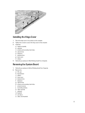
... f) keyboard trim g) base cover h) battery 4. Remove the: a) SD card b) ExpressCard c) battery d) base cover e) keyboard trim f) keyboard g) optical drive h) primary and secondary hard drive i) primary memory j) secondary memory k) video-card fan l) palmrest m) heatsink n) processor o) video-card heatsink. 51 Installing the Hinge Cover 1. Place the hinge cover in After Working Inside Your Computer. Removing...
... f) keyboard trim g) base cover h) battery 4. Remove the: a) SD card b) ExpressCard c) battery d) base cover e) keyboard trim f) keyboard g) optical drive h) primary and secondary hard drive i) primary memory j) secondary memory k) video-card fan l) palmrest m) heatsink n) processor o) video-card heatsink. 51 Installing the Hinge Cover 1. Place the hinge cover in After Working Inside Your Computer. Removing...
Owner's Manual
Page 55
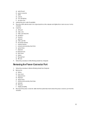
... board and remove the power connector port from the computer. 55 Install all the mini-cards (if available). 5. d) processor e) heatsink f) palmrest g) video-card fan h) secondary memory i) primary memory j) primary and secondary hard drive k) optical drive l) keyboard m) keyboard trim n) base cover o) battery p) ExpressCard q) SD card 7.
... board and remove the power connector port from the computer. 55 Install all the mini-cards (if available). 5. d) processor e) heatsink f) palmrest g) video-card fan h) secondary memory i) primary memory j) primary and secondary hard drive k) optical drive l) keyboard m) keyboard trim n) base cover o) battery p) ExpressCard q) SD card 7.
Owner's Manual
Page 60
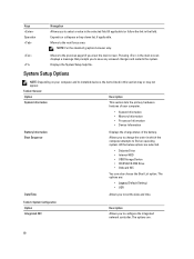
... also choose the Boot List option. Moves to set the date and time. System Setup Options NOTE: Depending on your computer. • System Information • Memory Information • Processor Information • Device Information Battery Information Boot Sequence Displays the charge status of the battery. All the below options are : 60 The...
... also choose the Boot List option. Moves to set the date and time. System Setup Options NOTE: Depending on your computer. • System Information • Memory Information • Processor Information • Device Information Battery Information Boot Sequence Displays the charge status of the battery. All the below options are : 60 The...
Owner's Manual
Page 73
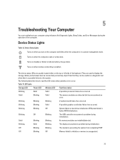
...and wireless devices connectivity and activity. Turns on steadily or blinks to indicate battery charge status. Solid Blinking Blinking No memory modules are usually located either on when wireless networking is in Option ROM initialization. The following table lists how to read...possible processor failure has occurred. The device status LEDs are installed/detected. Apart from completing POST Off Blinking Off Memory failed to initialize or memory is preventing the system from that they can troubleshoot your computer using indicators like Diagnostic Lights, Beep Codes, ...
...and wireless devices connectivity and activity. Turns on steadily or blinks to indicate battery charge status. Solid Blinking Blinking No memory modules are usually located either on when wireless networking is in Option ROM initialization. The following table lists how to read...possible processor failure has occurred. The device status LEDs are installed/detected. Apart from completing POST Off Blinking Off Memory failed to initialize or memory is preventing the system from that they can troubleshoot your computer using indicators like Diagnostic Lights, Beep Codes, ...
Owner's Manual
Page 75
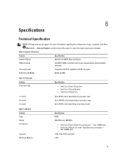
... with seven independently programmable channels Interrupt Levels Integrated I/O APIC capability with 24 interrupts BIOS Chip (NVRAM) 96 Mb (12 MB) Table 16. Memory Feature Type Speed Connectors Capacity Minimum Memory Specification DDR3 1600 MHz and 1866 MHz • Intel Core i5 and i7 Dual Core processors - 6 Specifications Technical Specification NOTE: Offerings may...
... with seven independently programmable channels Interrupt Levels Integrated I/O APIC capability with 24 interrupts BIOS Chip (NVRAM) 96 Mb (12 MB) Table 16. Memory Feature Type Speed Connectors Capacity Minimum Memory Specification DDR3 1600 MHz and 1866 MHz • Intel Core i5 and i7 Dual Core processors - 6 Specifications Technical Specification NOTE: Offerings may...
Owner's Manual
Page 77
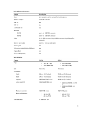
... Feature Audio Network Adapter USB 2.0 USB 3.0 eSATA\USB 2.0 IEEE1394: M4700 M6700 Video Memory card reader Docking port Subscriber Identity Module (SIM) port ExpressCard Smart card (optional... one 6-pin IEEE 1394 connector 15-pin VGA connector, 19-pin HDMI connector, 20-pin DisplayPort connector one 8-in-1 memory card reader one one one one M4700 • HD (1366 X 768) • FHD (1920 X 1080) 15...54 mm 1920 X 1080 pixels • 220 nits (HD) • 300 nits (FHD) 0° (closed) to 135° M6700 • HD+ (1600 X 900) • FHD (1920 X 1080) 17.3 inches 270.60 mm (10.65 inches) 416....
... Feature Audio Network Adapter USB 2.0 USB 3.0 eSATA\USB 2.0 IEEE1394: M4700 M6700 Video Memory card reader Docking port Subscriber Identity Module (SIM) port ExpressCard Smart card (optional... one 6-pin IEEE 1394 connector 15-pin VGA connector, 19-pin HDMI connector, 20-pin DisplayPort connector one 8-in-1 memory card reader one one one one M4700 • HD (1366 X 768) • FHD (1920 X 1080) 15...54 mm 1920 X 1080 pixels • 220 nits (HD) • 300 nits (FHD) 0° (closed) to 135° M6700 • HD+ (1600 X 900) • FHD (1920 X 1080) 17.3 inches 270.60 mm (10.65 inches) 416....


